


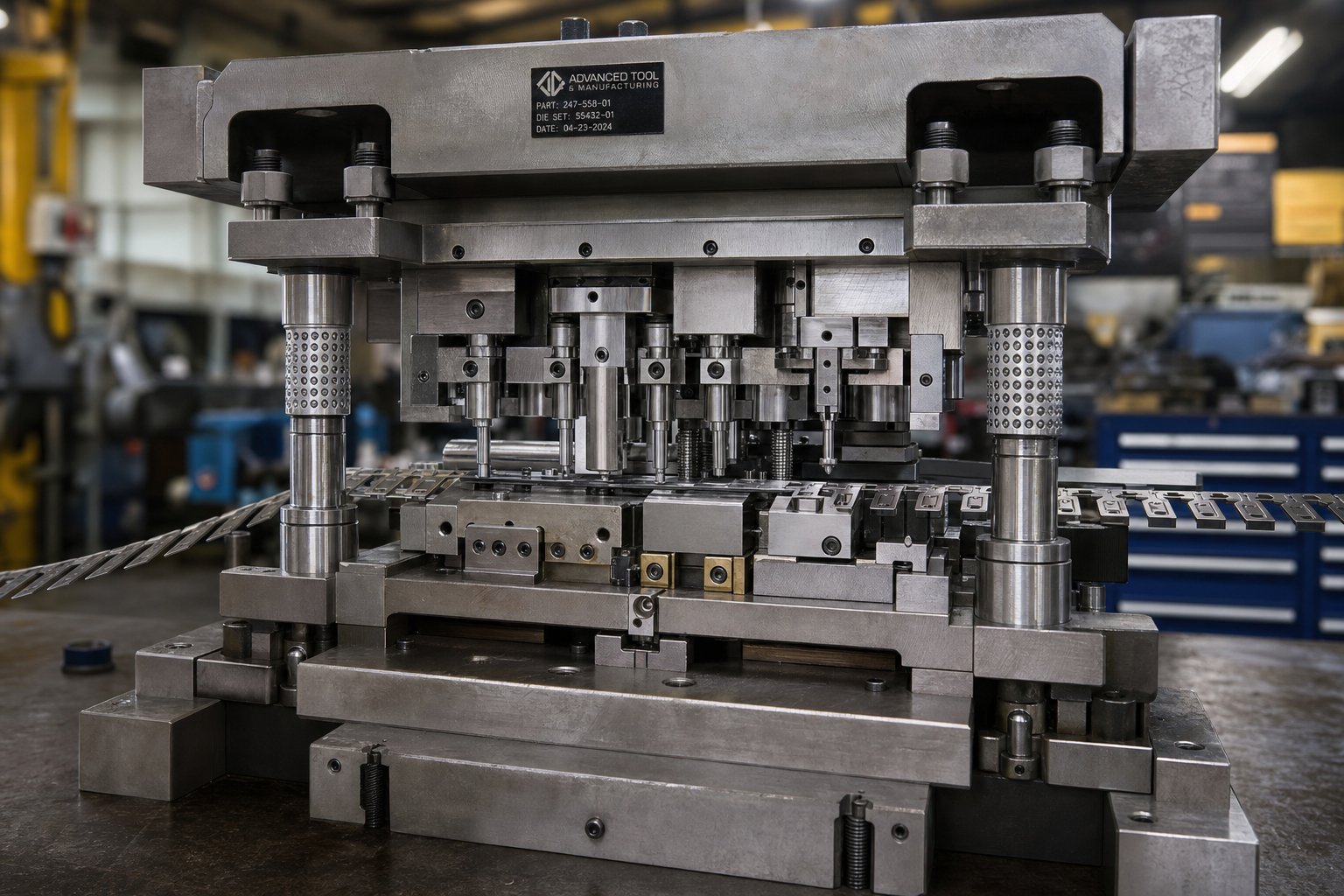
What Is Die Stamping Design and Why It Matters
Die stamping design is the engineering discipline of creating precision tool sets that shape sheet metal into finished parts through controlled force and material flow. It sits upstream of everything that happens on the press floor. Where metal stamping refers to the production operation itself, die stamping design focuses on the decisions, calculations, and geometry definitions that make that operation possible in the first place.
If you've ever asked what is stamping in manufacturing, the short answer is: applying force to sheet metal using matched tooling to cut, bend, or form a part. The longer answer involves hundreds of engineering variables that determine whether that process runs smoothly or falls apart after the first thousand hits.
What Die Stamping Design Actually Involves
Think of it as the bridge between a part concept and a production-ready tool. The inputs are straightforward: part geometry from a 3D model, material specifications (alloy, thickness, temper), and volume requirements that dictate how robust the tooling needs to be. The outputs are complete die assembly drawings, detail specifications for every component, and a strip layout that defines how raw coil becomes finished parts station by station.
A sheet metal stamping design package typically includes punch and die block dimensions, clearance values per material type, spring selections, guide system configurations, and tonnage calculations. Every dimension in that package either enables consistent production or introduces a failure mode waiting to surface.
Why Design Decisions Drive Production Outcomes
Here's the uncomfortable truth most stamping operations learn the hard way: problems that show up during production almost always originate in the design phase. Incorrect clearances cause burrs. Poor strip layouts waste material. Undersized components wear prematurely. Each of these issues traces back to a decision made months before the die ever sees a press.
Industry experience consistently shows that roughly 80% of stamping defects trace back to design-phase decisions rather than press-floor execution errors.
This makes stamping design the highest-leverage point in any program's lifecycle. A robust die design locks in part quality, minimizes scrap rates, extends die life, and keeps per-part costs predictable across millions of cycles. A flawed design, on the other hand, creates a chain of downstream problems that no amount of shimming or press adjustment can fully resolve.
The real cost of poor design isn't just the rework on the tool itself. It's lost production time, scrapped material, and delayed launches that compound across the entire program budget. Getting the engineering right at the source is the single most effective investment a stamping operation can make.
Types of Stamping Dies and How to Choose
Selecting the wrong die architecture is one of the most expensive mistakes in stamping die design. It locks you into a tooling approach that either under-delivers on capability or over-spends on complexity your part doesn't need. The decision isn't just about what's technically possible. It's about matching die type to part geometry, production volume, and budget reality before committing six figures to steel.
Four primary architectures cover the vast majority of metal stamping die design applications: progressive, transfer, compound, and combination dies. Each carries distinct trade-offs that engineers need to evaluate against their specific program requirements.
Progressive Die Design Considerations
Progressive dies are the workhorse of high-volume stamping. A strip of metal feeds through sequential stations, each performing a specific operation, cutting, bending, forming, until a finished part separates at the final station. The workpiece stays attached to a carrier strip throughout the process, which maintains alignment and eliminates part handling between operations.
From a design standpoint, progressive dies demand careful attention to carrier strip engineering, pilot hole placement for feed accuracy, and station sequencing that balances forces across the press stroke. They excel when you need tight tolerances on smaller parts at volumes exceeding 50,000 units. The trade-off? Higher upfront tooling cost and limited flexibility for design changes once the tool is built.
Key design advantages include minimal material waste, high strokes-per-minute capability, and the ability to produce complex geometries in a single press setup with reduced labor.
Transfer and Compound Die Trade-Offs
Transfer dies separate the workpiece from the strip early in the process, then use mechanical grippers to move individual blanks between independent stations. This architecture is ideal for large parts or deep-drawn components that can't stay connected to a carrier strip. The independent stations also allow for more intricate forming sequences, including threading, ribs, and knurling. Because there's no connecting web between parts, transfer dies can actually reduce material usage compared to progressive tooling on certain geometries.
Compound dies take the opposite approach: they perform multiple cutting operations simultaneously in a single press stroke. Imagine blanking and piercing happening at the exact same moment. This produces exceptionally flat parts because forces are balanced across the workpiece. Compound dies are the go-to choice for flatness-critical blanking applications like washers, shims, and electrical laminations. Tooling cost sits below progressive dies, but the process is limited to relatively simple, planar geometries.
Selecting the Right Die Architecture
Choosing between these types of stamping dies comes down to four variables: part size, annual volume, tolerance requirements, and budget constraints. A small connector terminal running two million units per year is a clear progressive die candidate. A large structural bracket at 10,000 units annually might justify a transfer setup. A simple flat washer at medium volumes points toward compound tooling.
The decision framework below maps each tool and die stamping architecture against its optimal application space:
| Die Type | Best Application | Volume Range | Relative Tooling Cost | Typical Lead Time | Design Complexity |
|---|---|---|---|---|---|
| Progressive | Small to mid-size parts with multiple features | 50K+ units/year | High | 12-20 weeks | High |
| Transfer | Large parts, deep draws, complex 3D forms | 10K-500K units/year | High | 14-24 weeks | High |
| Compound | Flat parts requiring blanking and piercing | 5K-500K units/year | Medium | 8-14 weeks | Low to Medium |
| Combination | Parts needing both cutting and forming in one stroke | 10K-200K units/year | Medium-High | 10-18 weeks | Medium |
Combination dies, worth mentioning separately, merge cutting and forming operations into a single stroke. They occupy a middle ground between compound and progressive approaches, useful when a part needs both shearing and bending but doesn't justify the complexity of a full progressive tool.
The critical takeaway for engineers: die architecture selection isn't a preference. It's an engineering decision driven by part requirements. Getting this wrong means either paying for complexity you don't need or fighting limitations that could have been avoided with a different tooling approach from the start.
Of course, choosing the right architecture is only the first step. Each of these die types relies on the same fundamental components, punches, die blocks, strippers, and alignment systems, whose individual design quality determines whether the tool actually delivers on its intended performance.
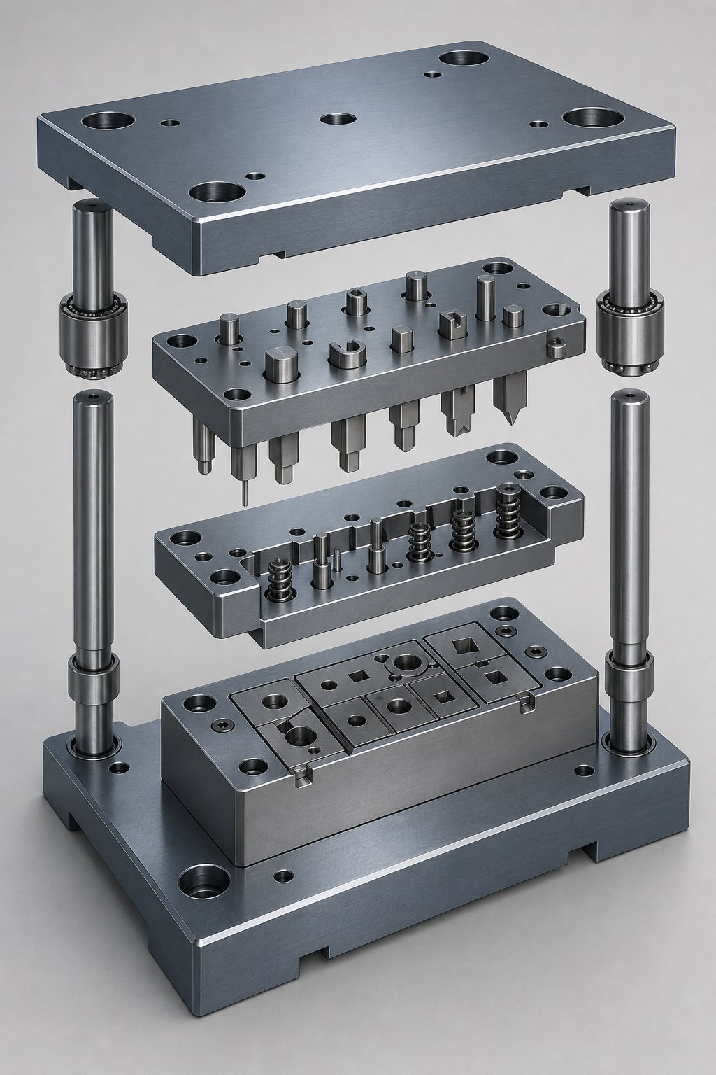
Essential Die Components and Their Design Functions
Every stamping die, regardless of architecture, is built from the same core family of components. Punches cut and form. Die blocks receive those punches with precise clearance. Strippers manage material behavior during and after each stroke. Guide systems keep everything aligned under thousands of pounds of force. Sounds straightforward, but the engineering rationale behind how each element is dimensioned and what stamping tool material gets selected is where die tooling design separates reliable production tools from chronic maintenance headaches.
You'll notice that many stamping failures aren't caused by a single catastrophic flaw. They're the result of marginal decisions stacking up across multiple components. A punch that's slightly too long, a stripper with inadequate spring force, a die shoe that deflects just enough to shift clearances. Understanding the "why" behind each component's specifications prevents these cumulative errors from reaching the press floor.
Punch and Die Block Design Principles
The punch is the active cutting or forming element, and its geometry directly controls edge quality, burr formation, and cutting force requirements. A well-designed punch has three distinct zones: the cutting edge (where it contacts the workpiece), the shank (where it's retained in the punch plate), and the transition between them. Each zone has its own dimensional and surface finish requirements.
Cutting edge profile matters more than most engineers realize. A flat-faced punch cuts cleanly but requires maximum tonnage because the entire cutting perimeter engages the material simultaneously. Adding a shear angle to the punch face, typically 1 to 1.5 times material thickness, staggers the cutting action across the stroke. This can reduce peak cutting force by 30-50%, which extends punch life and reduces shock loading on the press. The trade-off is that shear angles introduce lateral forces that can deflect thin punches, so they're best applied to larger cross-sections.
For the die block, engineers face a fundamental construction choice: solid or insert style. Solid die blocks are machined from a single piece of tool steel, offering maximum rigidity and simplicity. Insert-style die blocks use hardened inserts pressed or bolted into a softer holder plate. Inserts are easier to replace when cutting edges wear, reducing maintenance downtime significantly. For high-volume metal stamping tooling, insert construction is the standard approach because it allows localized replacement without rebuilding the entire die section.
Burr control traces directly back to the relationship between punch geometry and die block clearance. When clearance is correct and cutting edges are sharp, the fracture lines from the punch side and die side meet cleanly. Excessive clearance causes rollover and burr formation on the die side. Insufficient clearance creates secondary shear and rough edge conditions. The punch's cutting edge hardness, typically 58-62 HRC for tool steels like D2 or M2, determines how long that clean fracture relationship holds before resharpening is needed.
- Cutting edge length should be designed to prevent lateral bending during processing
- Shear angle selection must balance tonnage reduction against lateral force generation
- Punch-to-retainer fit (typically H7/h6) must prevent rotation and axial movement
- Die block escape angle below the cutting land allows slug clearance without binding
- Insert retention method (press-fit, shoulder, or screw) must resist ejection forces
- Surface finish on cutting edges should reach Ra 0.4 um or better to minimize friction
Strippers, Lifters, and Material Guidance Systems
Imagine a punch piercing through sheet metal. As it withdraws, the material naturally collapses around the punch body and tries to follow it upward. Without a stripping mechanism, that material either binds against the punch, causes the next feed to jam, or damages adjacent stations. Strippers solve this problem, but the type you choose has serious implications for die performance.
Spring strippers (also called pressure pads) are spring-loaded plates mounted to the upper die shoe that surround the cutting punches. They contact the strip material before the punches do, flattening any curvature caused by coil set and holding the workpiece tight against the die block during cutting and withdrawal. This prevents material from binding between punches, eliminates the hammering effect during stripping, and keeps the strip from shifting laterally during the cut.
Solid strippers (bridge strippers or plate strippers) are fixed plates bolted to the lower die. They're simpler and cheaper to manufacture, requiring no springs or guided spools. However, they don't hold material flat during cutting, which means punches must push the material down against the die block on their own. If the strip has any curvature, the material can bind between punches at different heights, causing deflection, chipping, or outright punch breakage. For precision progressive dies, spring strippers are the clear choice despite higher cost.
Lifter rails serve a different but equally critical function. In progressive dies, the strip must be elevated above the die surface between strokes so it can feed forward freely without dragging across forming stations or die inserts. Lifter pins, typically spring-loaded from below, raise the strip to a consistent feed height. The design parameter that matters most here is lift height: too little and the strip catches on formed features; too much and it introduces instability during feeding.
- Spring stripper force must exceed stripping force (typically 5-10% of cutting force) plus any blank-holding requirements
- Stripper-to-punch clearance should be less than half the die clearance to maintain guidance
- Lifter pin height must clear the tallest formed feature plus a safety margin for strip flutter
- Guide rail width tolerance controls strip lateral position and affects pilot engagement accuracy
- Material guidance tunnel length should provide enough engagement to prevent strip rotation during feeding
Die Shoe and Alignment Systems
The die shoe is the structural backbone of the entire assembly. Upper and lower shoes carry all the stamping die components, absorb the reaction forces from every cutting and forming operation, and maintain the spatial relationship between punch and die sections across millions of cycles. If the shoes deflect, every clearance in the tool shifts, and the precision you designed into individual components is lost.
Rigidity requirements scale with die size and total cutting force. Shoes are typically cast iron or steel plate, with thickness determined by the span between support points on the press bolster. A general guideline: shoe thickness should prevent more than 0.001 inch of deflection per foot of unsupported span under full load. Undersized shoes create uneven clearances at the die face edges, which shows up as burr on one side of the part and clean shear on the other.
Guide posts connect the upper and lower shoes and maintain their alignment throughout the press stroke. Two fundamental styles exist: friction (plain bearing) pins and ball bearing pins. Friction pins ride directly inside hardened bushings with approximately 0.0005 inch clearance. They handle high side thrust loads well and cost less, but generate friction that limits high-speed operation. The bushings are often lined with aluminum bronze containing graphite plugs to reduce wear.
Ball bearing guide pins ride on precision ball bearings within a cage, achieving a negative-slope fit where the pin-plus-bearing diameter is actually 0.0002 inch larger than the bushing bore. This produces ultra-precise alignment with minimal friction, making them the standard for high-speed progressive dies. The trade-off: ball bearing pins tolerate less side thrust than friction pins, so dies with significant unbalanced lateral forces may need supplemental heel blocks.
Alignment precision directly affects clearance consistency across the die face. Even a 0.001-inch shift between upper and lower shoes means the clearance on one side of a cut increases while the opposite side decreases by the same amount. On a tool designed with 0.004-inch clearance per side, that's a 25% variation, enough to produce visible burr differences from one edge of the part to the other.
- Die shoe material must match deflection limits: cast iron for general use, steel plate for high-precision or heavy-load applications
- Guide pin diameter should be sized for the expected side thrust, not just die weight
- Ball bearing pins require spring loading on bottom-mounted posts to ensure the cage enters the bushing before the pin
- Minimum two guide posts per die; four posts for long progressive dies to prevent shoe tipping
- Heel blocks with dissimilar wear plates (steel against aluminum bronze) should supplement guide pins when lateral forces exceed pin capacity
- Guide pin engagement length must ensure the pins are fully seated before any punch contacts the workpiece
These stamping die components don't operate in isolation. A perfectly designed punch paired with an inadequately guided shoe will produce the same defects as a worn tool. The interplay between component precision and structural rigidity is what separates a die that runs consistently from one that requires constant adjustment. And that interplay becomes even more complex when you factor in material-specific behaviors, where the same component dimensions that work for mild steel can cause immediate problems with stainless or aluminum.
Material Selection and Clearance Engineering
A die designed with perfect component geometry still fails if clearances don't match the material running through it. The same punch-to-die relationship that produces clean edges in mild steel can generate excessive burr in stainless or cause premature edge chipping in aluminum. Metal stamping materials behave differently under shear, bend differently during forming, and recover differently after the press stroke. Every one of those behaviors demands a design response.
This is where many engineers get burned. They apply a single clearance rule across all materials, copy spring-back assumptions from one alloy to another, or treat strip control features as an afterthought. The result is a tool that works on one material but creates defects the moment a spec sheet changes.
Clearance Values by Material Type and Thickness
Die clearance is expressed as a percentage of material thickness per side. It defines the gap between the punch cutting edge and the die opening, and it controls how the material fractures during blanking or piercing. Get it right, and the fracture lines from the punch side and die side meet cleanly with minimal burr. Get it wrong, and you're chasing edge quality problems for the life of the tool.
The general principle is straightforward: harder materials with lower yield-to-tensile ratios require larger clearances to provide the mechanical leverage needed for a clean break. But the specifics vary considerably across material families. For steel sheet stamping, research shows that while 10% per side is standard for mild steel, that same clearance produces the worst possible burr height on stainless steel. Advanced high-strength steels may need clearances as high as 21% per side for optimum edge-stretching ability.
| Material Family | Typical Thickness Range | Recommended Clearance (% per side) | Burr Behavior Notes |
|---|---|---|---|
| Mild Steel (CRS/HRS) | 0.5 - 3.0 mm | 8 - 12% | Clean shear with moderate rollover; burr increases gradually with clearance beyond optimum |
| Stainless Steel (Austenitic 304/316) | 0.3 - 2.5 mm | 12 - 16% | High work-hardening causes rapid burr growth at low clearances; avoid 10% per side |
| Stainless Steel (Ferritic 430) | 0.3 - 2.0 mm | 10 - 14% | Less sensitive than austenitic grades; moderate burr at standard clearances |
| Aluminum (5000/6000 series) | 0.5 - 3.0 mm | 6 - 10% | Soft material tears rather than fractures at excessive clearance; tight clearance reduces rollover |
| Advanced High-Strength Steel (AHSS) | 0.8 - 3.0 mm | 14 - 21% | Low yield-to-tensile ratio demands large clearance for edge stretch performance |
For stainless steel metal stamping, the work-hardening behavior changes the fracture mechanics significantly. Austenitic grades require about twice the press power of mild steel and generate substantially more frictional heat. These forces accelerate punch wear, which means edge degradation compounds the clearance problem over time. Specifying the correct initial clearance buys more cycles before resharpening becomes necessary.
Aluminum stamping presents a different challenge. Aluminum's lower shear strength means cutting forces are lower, but its tendency to gall against tooling surfaces creates adhesive wear on punch flanks. Many engineers default to mild steel clearance values for aluminum and wonder why they get excessive rollover and stringy burr. Tighter clearances, combined with polished punch surfaces and appropriate coatings, produce significantly better edge quality on aluminum alloys.
Spring-Back Compensation in Die Design
Every bend in sheet metal involves both elastic and plastic deformation. When the forming force releases, the elastic portion recovers, and the part springs open. The amount of recovery depends on material yield strength, bend radius relative to thickness, and grain direction. Higher-strength materials spring back more. Larger bend radii spring back more. And if your die doesn't account for it, your parts come out of spec.
Die designers use several compensation strategies. Overbending is the most common: the die bends the material past the target angle by a calculated amount so that spring-back returns it to the desired geometry. For example, if you need 90 degrees and the material springs back 3 degrees, the die is designed to form at 87 degrees. CNC press brakes automate this with material databases, but stamping dies require the compensation to be machined permanently into the tool geometry.
Bottoming, or coining, takes a different approach. Instead of bending past the target, the die applies concentrated pressure at the bend apex, forcing additional plastic deformation that reduces stored elastic energy. This method offers superior angular control with lower sensitivity to material thickness variation. The trade-off is higher tonnage requirements and potential surface marking on the workpiece interior.
For complex stampings with multiple bends, spring-back compounds across features. A part with three sequential bends, each springing back independently, can drift well outside tolerance if each bend isn't compensated individually. Die designers often use simulation-based prediction to map spring-back distribution across the part, then machine compensating geometry into each forming station rather than relying on a single correction factor.
Bypass Notch Design for Strip Control
In progressive die strip layouts, formed features and carrier geometry must coexist as the strip advances station to station. Bypass notches are small relief features cut into the strip that prevent interference between formed areas, tooling components, and adjacent stations. They sound minor, but poorly placed notches can weaken the carrier, cause strip distortion, or create feeding instability at production speeds.
Understanding negative and positive bypass notches in sheet metal stamping dies starts with their functional purpose. A positive bypass notch retains or guides material around a feature while maintaining enough carrier support for stable feeding. A negative bypass notch removes material to create clearance around tooling, formed geometry, or scrap paths. Both serve the same fundamental goal: letting the strip pass safely through all stations without collision or deformation.
Design rules for bypass notch geometry tie directly to material thickness and carrier width. The notch must remove enough material to clear formed features plus a safety margin for strip flutter and positional variation, but not so much that the remaining carrier cross-section becomes too weak to transmit feed forces without buckling or twisting. Sharp inner corners on notches create stress concentrations that can initiate tearing, especially in harder materials. Radiused transitions of at least one material thickness help distribute stress and prevent premature carrier failure.
The critical lesson: bypass notch problems typically surface during die tryout, but their root cause lives in the strip layout stage. If the strip layout doesn't account for how formed features, pilot holes, and scrap areas interact with carrier strength, no amount of tryout adjustment fixes the fundamental geometry conflict.
Material-specific parameters don't exist in isolation. Clearance values, spring-back compensation, and strip control features all interact within the same tool, and they all trace back to the strip layout, the single design artifact that orchestrates material flow through every station.
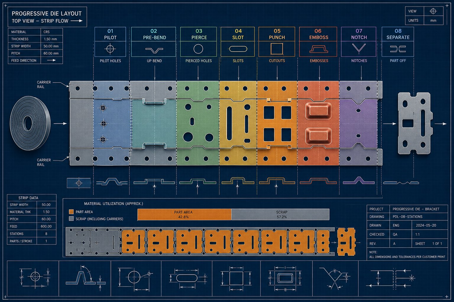
Strip Layout Optimization for Progressive Dies
Strip layout is the single design artifact that determines how much of your purchased coil becomes stamping parts and how much ends up in the scrap bin. It defines part orientation, feed pitch, carrier geometry, station sequence, and the scrap pattern the die must live with for its entire service life. A few millimeters of wasted bridge width or an inefficient nesting angle can cost thousands of dollars per production run when multiplied across millions of strokes.
For progressive dies producing stamped sheet metal components, the layout isn't just a drawing exercise. It's an economic decision that locks in material yield before a single punch touches steel.
Strip Layout Fundamentals and Material Utilization
Three variables drive material yield in any strip layout: strip width, feed pitch, and part orientation on the strip. Strip width equals the part's maximum dimension perpendicular to the feed direction plus bridges on both sides plus any carrier width needed for transport. Feed pitch, the distance the strip advances per press stroke, equals the part's maximum dimension in the feed direction plus one bridge.
Bridge thickness, the small web of material separating adjacent parts and between parts and the strip edge, follows a practical rule of thumb: approximately 1.25 to 1.5 times material thickness. Too thin and the bridge tears during feeding, jamming the die. Too thick and you're discarding usable material every stroke.
Part orientation opens up significant optimization potential. Tilting a part at an angle on the strip, known as angular pass or nesting, lets irregularly shaped geometries fit closer together. Imagine two L-shaped brackets rotated to interlock like puzzle pieces. This approach can push material utilization well above the 75% benchmark that most sheet metal stamping operations target. The trade-off is increased die complexity and potentially unbalanced cutting forces that require careful station design.
Coil width availability also constrains layout options. Standard coil widths from service centers come in fixed increments. If your optimal strip width falls between standard sizes, you're either paying for slit-to-width processing or accepting a slightly less efficient layout that uses a stock dimension. Experienced designers evaluate multiple layout orientations against available coil widths before committing to a final approach.
Station Sequencing and Pilot Placement
Station sequence determines the order in which piercing, forming, and blanking operations occur as the strip progresses through the die. Getting this wrong creates problems ranging from strip instability to cumulative dimensional drift across stations.
The guiding principle: create datum features first, distribute heavy cutting loads evenly, perform major forming only after the strip has adequate support, and leave the final cutoff until after the last calibration step. Piercing pilot holes early, typically at the first or second station, establishes the positional reference that all subsequent stations rely on. These pilots correct minor feed inaccuracies and hold the strip in precise registration before each press stroke.
Pilot-to-hole clearance for precision cold sheet metal stamping work is tight, typically around 0.0005 to 0.001 inch, which means the pilot holes themselves must be punched with minimal distortion. Placing pilots in the carrier strip rather than within the part geometry protects finished features from potential marking and keeps datum surfaces clean.
Force management across stations also matters. If all heavy blanking operations cluster at adjacent stations, the resulting load spike can deflect the die shoe and press frame unevenly. Distributing cutting forces by alternating heavy and light operations across the strip helps maintain consistent clearance relationships throughout the stroke. A useful estimation for cutting force is perimeter multiplied by thickness multiplied by material shear strength, with stripping force adding another 5-10% on top.
Scrap Reduction Through Design Optimization
Every percentage point of material yield improvement translates directly to cost savings on metal stamped parts. Three strategies deliver the most impact: carrier width minimization, common-line cutting, and part geometry cooperation.
Carrier width should be as narrow as structurally possible while still providing stable strip transport. A practical shop-floor guideline calls for carrier web width of at least two times material thickness to prevent buckling or tipping during feed. But geometry matters as much as raw width. A carrier with strategic stiffening ribs can be narrower than a flat carrier while maintaining equivalent rigidity.
Common-line cutting, where adjacent parts share a single cut edge rather than requiring separate bridges between them, eliminates one bridge width per part boundary. This technique works when parts have straight or compatible edge geometries and when the resulting scrap skeleton can still exit the die cleanly.
Sometimes the most effective scrap reduction comes from collaborating with product designers to modify part geometry itself. Small changes to corner radii, tab widths, or overall envelopes can shift a layout from 68% utilization to 78% without affecting part function. This design-for-manufacturability conversation ideally happens before part geometry is frozen, not after tooling quotes come back over budget.
A structured approach keeps strip layout decisions disciplined and prevents late-stage rework:
- Analyze part geometry and identify the developed blank dimensions, including all formed features unfolded flat
- Evaluate multiple part orientations and nesting strategies against standard coil widths
- Calculate material utilization for each candidate layout and rank by yield percentage
- Design the carrier strip type (solid, stretch web, or tab) based on forming requirements and transport stability
- Sequence stations to establish pilots first, distribute forces evenly, and separate forming from cutting where possible
- Specify bridge dimensions using material thickness multiples and verify carrier strength against total feed force
- Validate the final layout through simulation or manual strip modeling to confirm no interference between stations
Strip layout locks in the cost structure of every part the die produces. But even a perfectly optimized layout only works on paper until it's validated against real material behavior. That validation step, using simulation tools to predict thinning, wrinkling, and spring-back before cutting any tool steel, is what separates confident production launches from expensive die tryout surprises.
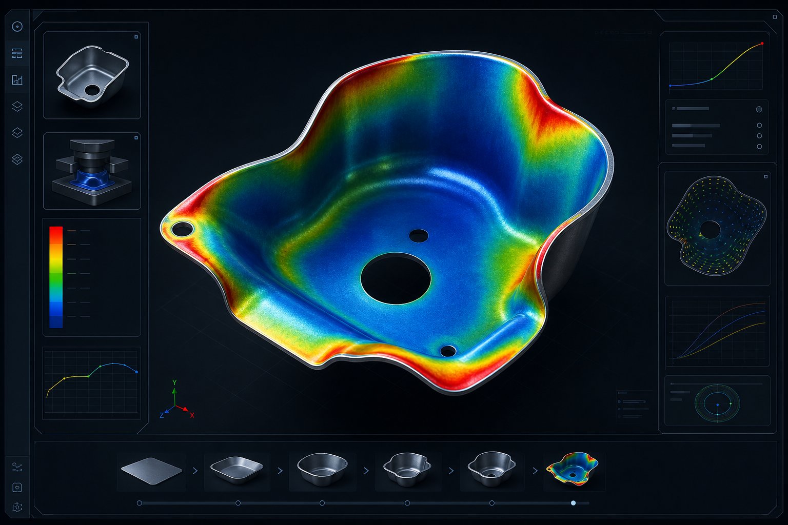
Simulation-Driven Design Validation
A strip layout can look flawless in CAD and still produce splits, wrinkles, or dimensional failures when metal actually flows through the tool. The gap between geometric design and physical reality is where simulation fills in. Modern finite element analysis (FEA) tools let engineers run the entire metal stamping process virtually, predicting exactly where material will thin, where it will wrinkle, and how much it will spring back, all before a single block of tool steel gets machined.
This isn't a nice-to-have step. It's the difference between a three-week die tryout and a three-day one. Every iteration you eliminate on the press floor, with its labor costs, machine time, and scrapped material, traces back to confidence built during simulation. Yet many engineering teams still treat forming analysis as optional, or worse, as something to do after the tool is already built and problems appear.
Forming Simulation and Feasibility Analysis
Finite element analysis works by dividing the sheet metal blank into thousands of small elements, then mathematically solving how each element deforms as it contacts punch and die surfaces under load. The solver tracks stress, strain, thickness change, and displacement at every node throughout the forming sequence. What comes out is a detailed map of material behavior that highlights problem areas long before they become scrap on the press floor.
The critical outputs engineers should evaluate include:
- Thinning distribution: areas where material stretches beyond safe limits, indicating potential splits or necking failures
- Wrinkling tendency: zones where compressive stresses cause the sheet to buckle, typically in flanges or unsupported draw walls
- Spring-back magnitude and direction: how much the part deviates from die geometry after force removal, mapped across every bend and contour
- Formability limit diagrams (FLD): plots that compare local strain states against the material's forming limit curve, showing exactly how much safety margin exists at each point
The formability limit diagram is particularly powerful because it translates complex strain data into a simple pass/fail visualization. Points below the forming limit curve are safe. Points near the curve indicate marginal conditions. Points above the curve predict failure. Engineers can immediately see which areas of the part are at risk and how much design change is needed to pull them back into the safe zone.
Beyond failure prediction, feasibility analysis establishes the boundary conditions for the entire stamping manufacturing process. Engineers should assess several criteria before committing to tool construction:
- Draw depth ratios: comparing cup or shell depth to blank diameter, with typical limits around 0.5 for first draws in mild steel
- Minimum bend radii: generally 1-2 times material thickness for ductile alloys, increasing for high-strength grades
- Stretch percentages: local elongation values compared against material-specific limits from tensile testing
- Tonnage estimates: total force required for all forming, blanking, and pad operations combined
These criteria interact with each other. A part that passes individual checks on draw depth and bend radii might still fail because combined strain from sequential operations exceeds the material's capacity in a specific region. Simulation captures these interactions holistically, something hand calculations simply cannot do for complex geometries.
Design Iteration and Prototype Validation
Simulation rarely gives a green light on the first pass. The real value shows up in the iteration loop: run a simulation, identify problems, modify the die geometry or process parameters, and run again. Each cycle takes hours on a computer rather than weeks on the press floor. A typical metal stamping manufacturing process simulation might cycle through five to ten design iterations before achieving acceptable results across all evaluation criteria.
What changes between iterations? Blank holder force adjustments to control wrinkling. Draw bead geometry modifications to regulate material flow. Punch radius increases to reduce thinning at critical corners. Addendum surface changes to redistribute strain more evenly. Each modification targets a specific simulation-identified problem, and the next run confirms whether the fix works without creating new issues elsewhere.
The question engineers face is: when is simulation confidence high enough to commit to production tooling? The answer depends on part complexity and risk tolerance. For simple blanking and bending operations, a clean simulation with adequate safety margins often justifies going directly to hardened production tooling. For deep draws, complex 3D forms, or materials with narrow forming windows, prototype metal stamping tooling provides physical validation that supplements simulation predictions.
Two prototype strategies exist, each with distinct trade-offs:
- Soft tooling prototypes use unhardened tool steel or even cast zinc alloys (Kirksite) to produce sample parts at low cost. They validate material flow, confirm spring-back predictions, and identify unforeseen forming issues. But soft tools wear quickly, sometimes lasting only 500-2,000 hits, and their dimensional behavior doesn't perfectly replicate hardened production conditions.
- Hard tooling prototypes use production-grade materials and heat treatment, essentially building a short-run version of the final tool. They provide the most accurate validation of part quality and process stability. The cost is substantially higher, but for high-risk programs, the insurance against a failed production tool justifies the investment.
A metal stamping prototype built from soft tooling costs roughly 30-50% of a full production die, while a hard prototype runs 60-80%. The decision matrix is straightforward: if the program volume and part criticality justify spending more upfront to de-risk production launch, hard prototypes make sense. For lower-stakes applications where simulation shows comfortable margins, soft tooling or even direct-to-production commitments reduce time-to-market.
Hybrid approaches also work. Engineers can validate draw operations with soft tooling while directly building hardened trim and pierce sections, since cutting operations are easier to predict analytically and carry less risk of fundamental geometry failure.
Tonnage Calculation and Press Selection
Every forming, cutting, and holding operation in a die consumes press capacity. Underestimating required tonnage causes the press to stall at bottom dead center. Overestimating wastes capital on unnecessarily large equipment. Accurate tonnage calculation ties die design directly to available manufacturing infrastructure.
For blanking and piercing, the standard formula is straightforward: cutting perimeter multiplied by material thickness multiplied by shear strength equals required tonnage. A 6-inch perimeter cut through 0.060-inch mild steel at 25 tons/sq. in. shear strength requires approximately 9 tons of cutting force. But a progressive die with 15 stations performing simultaneous cuts, forms, and draws can add up quickly.
Drawing operations use a similar calculation structure but substitute ultimate tensile strength for shear strength, because the cup or shell walls are in tension rather than being sheared. Blank holder pressure, typically 30-40% of the drawing force for mild steel, adds to the total. Spring strippers, lifter pins, nitrogen pressure pads, and driven cams all contribute additional loads that many engineers forget to include.
The complete tonnage calculation for a progressive die requires accounting for every station simultaneously:
- All piercing and blanking forces (perimeter x thickness x shear strength)
- Drawing forces at each draw station (perimeter x thickness x UTS)
- Blank holder and pad pressures
- Spring stripper forces (5-10% of total cutting force)
- Lifter pin and nitrogen spring loads
- Any cam-driven operations and their angular force components
- Final carrier cutoff and scrap separation forces
Adding shear angles to punches can reduce peak cutting force by 30-50%, which matters when total tonnage approaches press capacity limits. However, shear distributes the load over a longer stroke distance, which affects energy calculations. You can have sufficient tonnage but insufficient energy, a common cause of press jams at bottom dead center where flywheel speed drops below the threshold needed to complete the stroke.
Press selection must also consider where in the stroke the load occurs. A die that applies most of its tonnage very close to bottom dead center demands more energy from the press flywheel than one with loads distributed across a longer stroke. This relationship between tonnage, stroke position, and energy availability determines whether a given press can actually run the die at production speed without stalling.
Simulation-driven design validation typically reduces die tryout iterations by 50-70%, translating directly into shorter lead times, lower development costs, and faster production launches.
The tonnage calculation also influences die balance within the press. Loads should be distributed as evenly as possible across the press bed area. Off-center loading causes uneven slide deflection, which shifts clearances and accelerates wear on one side of the tool. When simulation reveals unbalanced forces, engineers can resequence stations or reposition the die relative to the press centerline to improve load distribution.
Simulation, feasibility analysis, and tonnage calculations form the analytical backbone that validates every upstream design decision. But all of this analysis assumes a specific production context: a particular volume, a defined press, a target die life. Change those assumptions, and the entire design approach shifts. What works for a million-unit program demands a fundamentally different engineering philosophy than a 5,000-piece prototype run.
Common Design Failures and Root-Cause Troubleshooting
When a metal stamped part comes off the press with burrs, dimensional errors, or surface defects, the instinct on the shop floor is to blame the die. Adjust the setup. Shim a station. Regrind a punch. These fixes treat symptoms, but the underlying problem usually lives in decisions made months earlier during design. As stamping expert Art Hedrick notes in The Fabricator, die design is critical, but it's only one element in a web of interacting variables. The key is understanding which defects truly originate from design-phase decisions versus those caused by process variation on the press floor.
What follows is a design-perspective root-cause analysis of the three most damaging failure categories: burr formation, dimensional drift, and material flow defects. Each one traces back to specific stamping design tips that, when followed during tool development, prevent the problem from ever reaching production.
Burr Formation and Edge Quality Defects
Burr is the single most common quality complaint on blanked and pierced parts. It drives secondary operations like deburring and tumbling, slows assembly, and in some cases creates a safety hazard on exposed edges. Yet burr is almost always a predictable outcome of design choices, not a random production problem.
Three design-phase variables control burr behavior:
Clearance specification. As covered in the material selection chapter, each alloy family has an optimum clearance window. Running outside that window, especially on the high side, increases rollover depth and creates a pronounced burr lip on the die side of the cut. For stamping examples where engineers applied mild steel clearances (8-10% per side) to austenitic stainless, the result is consistently excessive burr height because the work-hardening behavior of stainless requires 12-16% per side for clean fracture propagation. The design fix is straightforward: specify clearance values per material, not as a blanket percentage across the entire die.
Shear angle implementation. Flat-face punches engage the entire cut perimeter simultaneously, generating maximum peak force and shock loading. That shock accelerates edge degradation, and worn edges produce burr even when clearance is correct. Applying a shear angle of 1 to 1.5 times material thickness to the punch face reduces peak tonnage by 30-50% and distributes wear more evenly across the cutting edge. The trade-off, lateral force on the punch, is manageable with proper punch support through the stripper plate.
Tool steel hardness selection. A cutting edge hardened to 58-62 HRC (typical for D2 or M2 tool steels) maintains its geometry far longer than one at 54-56 HRC. The difference isn't subtle. At production volumes above 100,000 hits, every two points of Rockwell hardness can mean thousands of additional strokes between resharpening intervals. The design decision isn't just which steel to specify but also the carbide content, wear resistance characteristics, and surface treatment (TiN, TiCN, or DLC coatings) that extend edge life in abrasive material applications.
Punch-to-die alignment ties all three variables together. Even with correct clearance values and proper hardness, if the upper and lower die halves shift relative to each other during the stroke, clearance becomes uneven. One side of the cut gets tighter while the opposite side opens up, producing a characteristic burr pattern that appears on one edge only. This traces back to guide system design: ball bearing guide posts with adequate preload, heel blocks for lateral thrust management, and die shoe rigidity sufficient to prevent deflection under full cutting load.
Dimensional Drift and Tolerance Stack-Up
Imagine a progressive die with twelve stations. Each station introduces its own positional variation, perhaps only 0.001 to 0.002 inches per station. But if those errors are additive, station-to-station, the final part can be 0.012 to 0.024 inches off nominal by the time it reaches the last operation. That's enough to push sheet metal stamping tolerances beyond the typical +/-0.005 inch requirement on critical features.
This is where GD&T considerations become essential in die stamping design. Traditional coordinate dimensioning locates features relative to other features, creating dependency chains where each tolerance stacks onto the previous one. As GD&T fundamentals illustrate, using true position controls with datum reference frames eliminates these chains by locating every feature relative to a common set of datums rather than to each other.
Applied to progressive die design, this principle translates into a specific strategy: establish datum features (pilot holes) at the first station, then reference all subsequent operations back to those datums rather than to features created at intermediate stations. When each forming and piercing operation locates from the same pilot reference, errors don't compound. They remain independent.
Design strategies that minimize cumulative variation include:
- Placing pilot holes in the carrier strip at station one and using them as the master positional datum for all downstream operations
- Locating critical features from pilots rather than from previously formed geometry
- Designing stations so that the most tolerance-sensitive features are created as close as possible to pilot engagement points
- Using in-die sensors to detect pitch errors before they propagate through multiple stations
- Specifying metal stamping tolerances on the die build that are tighter than the part tolerance by at least 30% to provide a margin for process variation
Feed accuracy also plays a role. If the strip feed mechanism releases the material before the pilots engage, the strip floats momentarily without positional control. During that window, any residual stress in the carrier or unbalanced forming forces from the previous stroke can shift the strip. The design response is ensuring pilot entry begins before feed release ends, creating an overlap that maintains continuous strip registration.
Material Flow Defects and Their Design Causes
Wrinkling, splitting, and surface marking are the three material flow defects that most frequently kill production runs. Each has a distinct design-phase root cause, and each can be prevented through specific tooling decisions made long before the die reaches tryout.
Wrinkling from insufficient blank holder pressure. When sheet metal flows into a draw cavity under compressive stress with inadequate restraint, it buckles. The wrinkles that form in the blank holder area don't just stay there. As root-cause analysis confirms, wrinkled material that gets forced over a draw bead or into the die cavity creates restrictive forces that cause excessive thinning and eventual splitting downstream. The design fix involves specifying blank holder pressure adequate to maintain sheet tension (typically 30-40% of drawing force for mild steel), incorporating draw beads where localized flow control is needed, and ensuring standoffs or equalizers maintain uniform pressure across the entire hold-down surface.
Splitting from excessive draw depth. Every material has a limiting draw ratio, the maximum ratio of blank diameter to punch diameter it can sustain in a single operation. Exceed it, and the cup wall fails in tension. Common deep draw failures also point to clearance between punch and die as a major contributor: if this gap is too small, too large, or uneven, the material fractures during drawing. The design-phase prevention involves calculating draw ratios during feasibility analysis, splitting deep draws across multiple stations to reduce strain per hit, and verifying punch-to-die clearance uniformity before tool construction.
Surface defects from inadequate lubrication provisions. Die design must account for how lubricant reaches and stays on critical forming surfaces. Without designed-in lubricant channels, reservoirs, or textured surfaces that retain oil film, metal-to-metal contact under high pressure generates galling, scoring, and surface pickup. These aren't operator errors. They're design omissions. Features like oil grooves in draw rings, micro-textured punch surfaces, and lubricant application ports positioned upstream of forming stations ensure consistent film coverage throughout the stroke cycle.
A structured troubleshooting checklist links visible symptoms to their design-phase root causes:
- Burr on one side of part only: uneven clearance from guide system misalignment or die shoe deflection under load
- Burr height increasing over production run: punch edge wear from insufficient hardness or missing surface coating
- Holes out of position: pilot-to-strip engagement timing incorrect, or tolerance stack-up across stations
- Progressive dimensional drift: cumulative station errors from features referenced to other features rather than to master datums
- Wrinkling in flange areas: blank holder pressure too low or uneven standoff heights across the hold-down surface
- Splitting at draw walls: draw ratio exceeds material limit, or punch radius too tight for the material thickness
- Galling or scoring on formed surfaces: missing lubricant provisions in die design, or die surface finish too rough (above Ra 0.8 um)
- Part not flat after blanking: unbalanced cutting forces or residual stress in incoming material not addressed by stripper pressure
- Inconsistent spring-back: incoming material property variation combined with inadequate compensation strategy in the forming geometry
The common thread across all these failures: prevention costs less than correction. Every defect on this list can be anticipated during the design phase through proper analysis, correct parameter specification, and structured design review. Die tryout should validate a sound design, not serve as the first opportunity to discover that fundamental engineering decisions were wrong.
These failure patterns also reveal something about how tooling investment should scale with production demands. A tool running 5,000 parts per year can tolerate design compromises that would be catastrophic at 500,000 units. Understanding how volume expectations should reshape die engineering decisions, from material selection to station count to maintenance strategy, is what separates cost-effective tooling from tools that either over-invest or under-deliver.

Designing for Different Production Volume Tiers
A die that's perfect for two million annual units is wildly over-engineered for a 2,000-piece validation run. And a tool built to prototype stamping standards will self-destruct inside of a month at production speeds. Volume isn't just a number on a purchase order. It fundamentally reshapes every engineering decision: tool steel grade, station count, component construction style, maintenance accessibility, and the economic math that justifies each choice.
The mistake engineers make most often? Applying a single design philosophy across all volume tiers. The result is either tooling that costs three times what the program can support or tooling that wears out before the first reorder ships.
Prototype and Short-Run Die Design Strategies
When you need 500 to 5,000 parts, the design priority flips from longevity to speed and cost containment. Every dollar spent on tooling gets amortized across a small number of units, so upfront investment dominates the per-part economics. A custom progressive die running $12,000 adds $2.40 per part at 5,000 units but only $0.12 per part at 100,000 units. That math drives every design decision at the prototype tier.
Short-run die design strategies include:
- Using unhardened or semi-hardened tool steels (A2 at 54-56 HRC rather than D2 at 60-62 HRC) that machine faster and cost less, accepting shorter die life in exchange
- Reducing station counts by combining operations where possible, even at the cost of slightly higher per-station strain on the material
- Employing solid die block construction rather than insert-style, since replacement frequency isn't a concern at low volumes
- Simplifying guide systems to friction-type pins rather than ball bearing posts, adequate for slower press speeds and fewer total cycles
- Skipping redundant features like backup pilots, secondary sensing, or spare insert pockets that add build time without payback at low volumes
Soft tooling prototypes, sometimes cast from zinc alloys like Kirksite, occupy the extreme low end. They validate material flow and confirm spring-back predictions for 500-2,000 hits before wearing beyond tolerance. For prototype stamping applications where the design might still change, this disposable approach prevents expensive rework on hardened tools that can't easily be modified.
The trade-offs are real: shorter die life (typically 10,000-50,000 hits versus hundreds of thousands), wider tolerances from less rigid construction, and higher per-part cost. But for proving out concepts, validating fit in assemblies, or filling a bridge order while production tooling is being built, these compromises are not just acceptable but economically necessary.
High-Volume Production Die Design Requirements
At volumes exceeding 100,000 annual units, the economic equation inverts completely. Tooling cost becomes a rounding error in the per-part calculation. What matters is uptime, consistency, and die life measured in millions of cycles. Production metal stamping at this scale demands engineering decisions that would look absurdly over-specified for a short run but pay back many times over across the program's lifetime.
For industrial metal stamping programs, Class A progressive tooling is the standard. These dies feature replaceable wear components, guided strippers with precision ball bearing guide posts, and hardened steel or carbide cutting inserts. Conventional dies might last up to one million parts. Class A tooling with proper maintenance can exceed that significantly.
Carbide inserts are the defining feature of high-volume die design. Tungsten carbide cutting edges last 5-10 times longer than conventional tool steel, which means fewer press stoppages for resharpening and more consistent edge quality across extended production runs. The design considerations change: carbide is brittle and must be supported by shock-absorbing backing materials, processed carefully to avoid binder degradation during grinding, and sometimes coated (TiN, TiCN) for additional wear resistance.
Additional forming stations also characterize high-volume tools. Where a short-run die might form a feature in two stations at higher strain per hit, a production die spreads the same operation across three or four stations. Less strain per station means less work hardening between hits, better surface finish, more predictable spring-back, and dramatically longer die life. Metal stamping for large parts especially benefits from this approach because the higher forming forces involved amplify wear rates on tooling surfaces.
Redundant features that seem excessive at low volumes become essential at scale:
- Backup pilot stations that maintain registration if a primary pilot pin breaks
- In-die sensing (missfeed detection, slug retention monitors, part-out sensors) that stops the press before a failure cascades into die damage
- Quick-change insert pockets that allow worn cutting edges to be swapped during a scheduled break rather than requiring a full die pull
- Standardized fastener metal stamping components (screws, dowels, springs) sourced from common catalogs for rapid maintenance without custom procurement delays
Cost-Driven Design Decisions
The real engineering challenge isn't designing for one volume tier. It's deciding where your program falls and making investment decisions that match reality rather than optimism. Every upgrade, whether it's carbide versus tool steel, four stations versus three, or ball bearing posts versus friction pins, carries a cost premium that's only justified above a certain volume threshold.
The break-even math is specific to each decision. A carbide insert set might add $3,000 to tooling cost but save $0.002 per part in reduced downtime. That investment breaks even at 1.5 million parts. Below that volume, tool steel delivers equivalent economics. Above it, carbide pays for itself repeatedly. Engineers should run this calculation for every major design decision rather than defaulting to either the cheapest or the most durable option.
In-die sensing follows similar logic. A misfeed sensor package might cost $2,000-5,000 but prevents die crashes that cost $15,000-50,000 to repair. If crash probability is once per million strokes, the sensor pays for itself in programs exceeding a few hundred thousand hits. For shorter runs, the statistical likelihood of a crash may not justify the investment.
| Design Parameter | Prototype / Short-Run | Mid-Volume (10K-100K) | High-Volume (100K+) |
|---|---|---|---|
| Tooling Cost Range | $3,000 - $15,000 | $15,000 - $50,000 | $50,000 - $200,000+ |
| Per-Part Cost Impact | High ($1.00 - $5.00+ tooling amortization) | Moderate ($0.15 - $1.00) | Low ($0.01 - $0.10) |
| Expected Die Life | 10,000 - 50,000 hits | 250,000 - 1,000,000 hits | 1,000,000 - 10,000,000+ hits |
| Tool Steel Grade | A2, S7 (semi-hardened) | D2, M2 (fully hardened) | Carbide inserts, PM steels |
| Guide System | Friction pins, two-post | Ball bearing, four-post | Ball bearing with preload, heel blocks |
| Station Strategy | Fewer stations, higher strain per hit | Balanced station count | Additional stations for reduced strain |
| Maintenance Features | Minimal (solid construction) | Replaceable inserts at wear points | Quick-change inserts, in-die sensing, spare pockets |
| Typical Applications | Design validation, bridge production, niche parts | Consumer products, mid-tier assemblies | Automotive, appliance, high-demand fasteners |
Notice how the boundaries between tiers aren't rigid. A part with extremely tight tolerances might justify high-volume construction practices at mid-volume quantities because the cost of scrap from less precise tooling exceeds the premium for better components. Conversely, a non-critical cosmetic part at high volumes might tolerate mid-tier construction if surface finish requirements are forgiving.
Engineers working across these volume tiers benefit from partnering with die solution providers who can adapt tooling strategies to match program scale. YICHEN offers custom stamping die solutions spanning prototype through production tooling, with expertise in die structure, component selection, and material flow optimization that adjusts to each project's volume reality. Having a single partner who understands the full spectrum prevents the disconnect that happens when prototype tools are designed by one team and production tools by another with no continuity in engineering philosophy.
The volume tier decision also influences how you approach design validation. High-volume programs justify extensive simulation and hard prototyping because the cost of getting it wrong multiplies across millions of parts. Short-run programs may accept more tryout iteration because the financial exposure is bounded. But regardless of volume, the fundamental engineering principles remain constant. What changes is how much you invest in executing them.
Putting Die Stamping Design Principles Into Practice
Knowing the engineering principles is one thing. Applying them consistently across every new program, under deadline pressure, with shifting part requirements and budget constraints, is where most teams fall short. The failures covered throughout this metal stamping guide share a common thread: they weren't caused by lack of knowledge. They were caused by skipped steps, unchecked assumptions, and design decisions made in isolation from downstream realities.
What separates teams that launch tools cleanly from those stuck in endless tryout cycles isn't talent. It's process discipline. A structured workflow that forces critical questions early, validates assumptions through simulation, and catches errors before they're machined into hardened steel.
Design Checklist for New Die Programs
Every new metal stamping design project benefits from a prioritized sequence of decisions. Skip or reorder these steps and you'll find yourself solving problems that didn't need to exist. Use this checklist as a gate review framework, where each item gets verified before the next phase begins:
- Confirm part geometry is frozen and all GD&T requirements are documented, including datum structure, critical-to-quality features, and allowable surface conditions
- Verify material specification completely: alloy, temper, thickness tolerance band, grain direction requirements, and any incoming quality constraints
- Determine annual volume projections and program life to select the appropriate tooling tier (prototype, mid-volume, or production class)
- Perform feasibility assessment: draw depth ratios, minimum bend radii, stretch percentages, and preliminary tonnage estimates against available press capacity
- Select die architecture (progressive, transfer, compound, or combination) based on part size, volume, tolerance requirements, and budget
- Specify material-specific clearance values per cutting station rather than applying a single blanket percentage across the tool
- Complete strip layout optimization with material utilization calculated, carrier strength verified, and bypass notch geometry confirmed
- Sequence stations with pilot placement, force distribution, and forming-before-trimming logic validated
- Run forming simulation and confirm all regions pass formability limit criteria with adequate safety margin
- Calculate spring-back compensation values for each bend station and incorporate into forming geometry
- Verify total tonnage including all cutting, forming, pad, stripper, and cam forces against press rating at the planned stroke position
- Review die shoe rigidity, guide system selection, and alignment strategy for the expected load and speed conditions
- Specify tool steel grades, hardness requirements, and surface treatments for each wear component based on material abrasiveness and volume targets
- Incorporate error-proofing features: offset dowels, asymmetric guides, and components that physically cannot be installed incorrectly
- Document maintenance intervals, resharpening allowances, and critical spare components before the tool ships to production
This sequence isn't arbitrary. Each step depends on information confirmed in the previous one. Jumping to strip layout before feasibility is confirmed, or selecting tool steels before volume tier is established, creates rework loops that consume engineering hours without moving the program forward.
Building a Stronger Die Design Practice
The checklist handles individual programs. Building a consistently strong metal stamping manufacturing practice requires something broader: structural changes to how design teams interact with product engineers, how validation workflows are enforced, and how institutional knowledge compounds over time.
DFM collaboration is the highest-leverage improvement most organizations can make. When die engineers engage with product designers before part geometry is frozen, they can identify manufacturability issues that cost nothing to fix in CAD but tens of thousands to accommodate in tooling. A radius change, a tolerance relaxation on a non-critical feature, a slight geometry shift that improves nesting, these conversations happen easily at the concept stage and become painful change orders once tooling is quoted.
The stamping process in manufacturing doesn't start when metal hits the die. It starts when a product designer makes geometry decisions that the die must accommodate. Bridging that gap, through structured DFM reviews at defined design milestones, prevents the scenario where a die engineer receives a frozen part print that's inherently difficult to stamp and has no room for negotiation.
Simulation-first workflows represent the second structural improvement. Teams that treat forming analysis as a mandatory design gate, not an optional supplement, catch problems when they're free to fix. Teams that skip simulation and rely on die tryout to reveal issues pay for that shortcut in machine time, material waste, and schedule delays. The economics are unambiguous: an hour of simulation time costs a fraction of an hour of press tryout time, and it yields answers faster.
Structured design reviews add a third layer of protection. Even experienced engineers develop blind spots on projects they've been working on for weeks. A fresh set of eyes reviewing clearance specifications, strip layout assumptions, and tonnage calculations catches errors that the original designer has looked past a dozen times. These reviews don't need to be elaborate. A 30-minute peer review against the checklist above catches the majority of design-phase errors before they reach tool construction.
Beyond internal process, the stamping process in manufacturing benefits from external expertise, particularly for design-intensive challenges that exceed a team's routine experience. Complex die structures, unusual material combinations, tight clearance engineering, or burr-critical applications often benefit from the perspective of a dedicated tooling partner who has solved similar problems across diverse industries. YICHEN serves this role for engineers seeking collaborative die design expertise, particularly on projects involving die structure optimization, punch and lifter design, clearance engineering, and material flow control. The distinction matters: a tooling partner who participates in the design process, contributing engineering judgment on component selection and forming strategy, delivers fundamentally different outcomes than a vendor who simply builds to a provided print.
Die stamping design is ultimately a discipline where the quality of upstream thinking determines downstream results. Every principle in this metal stamping guide, from clearance engineering to simulation validation to volume-appropriate tooling investment, points toward the same conclusion: the press floor rewards preparation and punishes shortcuts. Engineers who build systematic rigor into their design workflow don't just produce better tools. They produce them faster, with fewer iterations, and with predictable outcomes that hold across the life of the program.
Frequently Asked Questions About Die Stamping Design
1. What is the difference between die stamping design and metal stamping?
Die stamping design is the upstream engineering discipline focused on creating the precision tool sets, including defining clearances, strip layouts, station sequences, and component specifications. Metal stamping is the production operation that uses those tools to shape sheet metal. Design decisions made months before production determine whether the stamping process runs efficiently or creates chronic defects. About 80% of stamping quality issues trace back to choices made during the design phase rather than press-floor execution.
2. How do you determine the correct die clearance for different materials?
Die clearance is expressed as a percentage of material thickness per side and varies by alloy. Mild steel typically requires 8-12% per side, austenitic stainless steel needs 12-16%, aluminum works best at 6-10%, and advanced high-strength steels may need 14-21%. The principle is that harder materials with lower yield-to-tensile ratios need larger clearances for clean fracture propagation. Applying a single clearance value across all materials is a common mistake that leads to burr formation and poor edge quality. Partners like YICHEN (yichen-group.com/stamping-die/) can help engineers specify material-specific clearance values for custom die solutions.
3. What causes burr in stamped parts and how can die design prevent it?
Burr formation stems from three primary design-phase variables: incorrect clearance specification for the material being stamped, missing shear angles on punch faces that cause shock loading and accelerated edge wear, and insufficient tool steel hardness that allows cutting edges to degrade prematurely. Punch-to-die alignment also plays a critical role since even correct clearances become uneven if the guide system allows upper and lower die halves to shift during the stroke. Preventing burr requires specifying clearance per material type, applying 1-1.5x material thickness shear angles, selecting 58-62 HRC tool steels, and designing rigid guide systems with ball bearing posts.
4. When should you use a progressive die versus a transfer die?
Progressive dies are optimal for small to mid-size parts at volumes exceeding 50,000 units per year where tight tolerances and high strokes-per-minute are needed. The workpiece stays on a carrier strip through sequential stations. Transfer dies suit large parts or deep-drawn components that cannot remain connected to a strip, typically at 10,000-500,000 annual units. The decision depends on four variables: part size, annual volume, tolerance requirements, and budget. Large structural brackets or complex 3D forms generally point to transfer tooling, while connector terminals and small brackets favor progressive architecture.
5. How does production volume affect die stamping design decisions?
Volume fundamentally reshapes every engineering choice. Prototype runs (500-5,000 parts) use semi-hardened steels, fewer stations, and simplified guide systems to minimize upfront cost. High-volume programs (100,000+ annual units) justify carbide inserts, additional forming stations for reduced strain per hit, ball bearing guide posts with preload, and in-die sensing for crash prevention. The break-even math is specific to each decision. For example, carbide inserts adding $3,000 to tooling cost but saving $0.002 per part only pay back above 1.5 million hits. Engineers should calculate these thresholds rather than defaulting to one approach across all programs.


