
Progressive Die Stamping for Truck Parts: Cut Cost, Not Quality
What Progressive Die Stamping Means for Truck Manufacturing
When you need millions of structurally consistent brackets, clips, and mounting hardware for a truck platform, the manufacturing method you choose determines both your per-part cost and your quality floor. Progressive die stamping has become the dominant production strategy for these components, and understanding why starts with understanding the process itself.
Defining Progressive Die Stamping in a Truck Manufacturing Context
Progressive die stamping is a high-volume metal forming process in which a continuous strip of metal feeds through a single die containing multiple stations, each performing a distinct operation - piercing, forming, bending, or cutting - so that a finished truck component is produced with every stroke of the press.
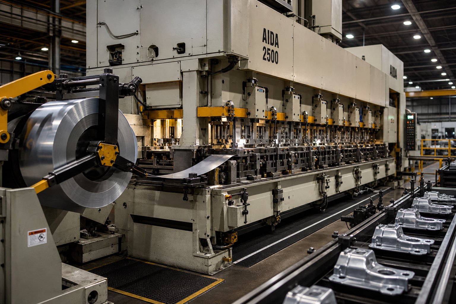
So what is a progressive die in practical terms? Imagine a coil of high-strength steel loaded onto a decoiler, straightened through a leveler, and fed into a press at a fixed pitch distance. With each press stroke, the strip advances one station forward. Station one might pierce pilot holes. Station two forms a flange. Station three coins a mounting surface. The final station separates the completed part from the carrier strip. The entire sequence happens continuously, without repositioning or operator intervention, at speeds ranging from 25 to over 300 strokes per minute depending on part complexity.
For truck parts specifically, progressive metal stamping handles the material gauges (typically 1.0 mm to 6.0 mm), the geometric complexity (compound bends, multiple hole patterns), and the annual volumes (often 50,000 to several million pieces) that define this sector. Progressive die metal stamping is particularly well-suited to the structural brackets, cross-member reinforcements, cab clips, and exhaust hangers that truck platforms consume in high quantities.
Why Truck OEMs Rely on Progressive Dies Over Other Methods
Truck OEMs, Tier-1, and Tier-2 suppliers choose progressive dies over alternative forming methods for a straightforward reason: once tooling is validated, the process delivers identical parts at minimal labor cost, stroke after stroke. A single press operator can monitor a prog die producing thousands of finished components per hour. Consistency across a production run of several million cycles eliminates the downstream rework and fit-up problems that plague less repeatable methods.
Progressive stamping also consolidates what would otherwise be multiple separate operations - punching, bending, forming, trimming - into one continuous pass through the die. Fewer handling steps means lower defect risk and faster throughput, both critical when you are feeding a truck assembly line running on tightly sequenced just-in-time delivery.
This article serves as an engineering-focused resource for buyers and design engineers evaluating whether progressive die stamping fits their truck program requirements. The sections ahead walk through the step-by-step process, ideal part candidates, material selection, design-for-manufacturability rules, process comparisons, cost analysis, and supplier qualification criteria - everything needed to make an informed tooling decision.
How the Progressive Die Process Produces Truck Components Step by Step
A flat coil of steel enters one end of the press, and a finished truck bracket exits the other - but what happens between those two points determines whether you get a reliable structural component or a scrap bin full of rejects. The progressive die stamping process breaks down into a precise sequence of station operations, each one building on the last.
Strip Feeding and Material Straightening for Heavy-Gauge Coils
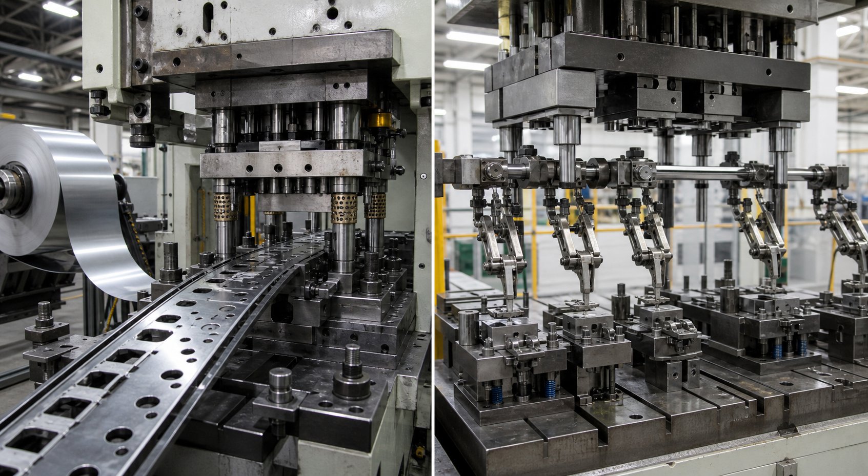
Truck parts typically use material in the 1.0 mm to 6.0 mm thickness range - heavier than most consumer electronics or appliance stampings. That extra gauge means the coil carries significant internal stress from winding. Before the strip reaches the first die station, it passes through a decoiler and a precision leveler that removes coil set, crossbow, and edge wave. A servo roll feeder then advances the strip at a fixed pitch distance with each press stroke, positioning it within thousandths of an inch for the operations ahead.
For heavy-gauge truck materials, feed accuracy is non-negotiable. Even slight misalignment compounds across multiple stations, producing out-of-tolerance holes and misaligned bends on the finished part.
Piercing, Forming, and Cutoff Stations Explained
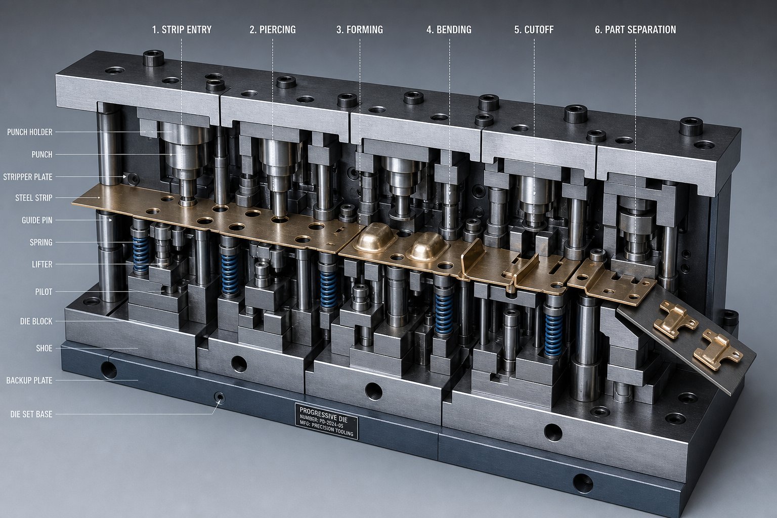
Picture a frame rail bracket moving through a progressive stamping die. Here is the typical station sequence that transforms flat strip into a finished truck component:
- Pilot hole piercing - The first station punches precision pilot holes that register the strip at every subsequent station. These holes are the positional reference for the entire part.
- Feature piercing and notching - Mounting bolt holes, slot patterns, and edge notches are cut. For a cab mounting clip, this might include two bolt clearance holes and a wire-routing slot.
- Forming and bending - The strip is bent into its functional geometry. A frame rail bracket might require a 90-degree flange and a secondary offset bend to clear an adjacent crossmember.
- Coining or embossing - High-pressure stations refine critical surfaces. Coining a bearing surface on a suspension mounting plate, for example, achieves flatness tolerances that simple bending cannot.
- Cutoff and separation - The final station severs the finished part from the carrier strip. The completed bracket drops onto a conveyor or into a bin, and the remaining skeleton strip exits as recyclable scrap.
Each station adds one feature set per press stroke. A simple exhaust hanger might need only four stations, while a complex cross-member reinforcement with compound angles and multiple hole patterns could require ten or more. More stations mean a longer die and higher tooling cost - but they also mean fewer secondary operations downstream.
Press Tonnage and Feed Rate Considerations for Truck Parts
The progressive stamping process for truck components demands more press force than lighter-gauge work. Piercing and forming high-strength steel at 4.0 mm or above can require a progressive die press rated at 200 to 600 tons, depending on strip width and the number of simultaneous operations per stroke. A die stamping press running heavy-gauge truck brackets typically operates at 25 to 80 strokes per minute - slower than high-speed electronics stamping, but still producing hundreds to thousands of finished parts per hour.
Feed rate, station count, and press tonnage are interdependent variables. Increasing part complexity (adding bends or tighter tolerances) often means adding stations, which lengthens the die and may require a press with a larger bed. The progressive stamping press must accommodate both the total forming force and the physical footprint of the tool.
These mechanical realities shape which truck parts are strong candidates for the process - and which ones push beyond its practical limits.
Truck Parts That Are Ideal Candidates for Progressive Die Stamping
Not every metal part on a truck belongs in a progressive die. The process excels when part geometry stays flat or shallow-draw, hole patterns are repeatable, material thickness sits within coil-feeding range, and annual demand is high enough to justify tooling investment. Knowing which parts fit - and which do not - separates a smart tooling decision from an expensive mistake.
Structural Brackets and Mounting Plates
Structural components are where progressive die stamped brackets deliver the clearest ROI. These parts share common traits: moderate complexity, consistent hole patterns, and volumes that often reach hundreds of thousands per year. High volume stamping justifies the tooling spend because the per-piece cost drops dramatically once the die is running.
- Frame rail brackets - Flat profiles with flanged edges and two to four bolt holes. Geometry is typically a single-plane bend with moderate draw depth, making strip carry straightforward.
- Cross-member reinforcements - Shallow channel sections with pierced mounting holes at fixed intervals. Their symmetrical profiles keep the strip balanced through forming stations.
- Suspension mounting plates - Thick-gauge flat plates (3.0 mm to 5.0 mm) with coined bearing surfaces and precision bolt patterns. Minimal forming keeps station count low even at heavy gauge.
Each of these parts stays stable on the carrier strip throughout the die because the formed features are shallow relative to the strip width. That stability is what makes them natural fits for an automotive stamping die layout.
Electrical Connectors and Cab Hardware
Smaller, lighter-gauge truck components are equally strong candidates - sometimes even better ones, because their thinner materials allow faster press speeds and longer die life.
- Electrical connector housings - Thin-gauge (0.8 mm to 1.5 mm) parts with multiple small piercings, tabs, and shallow box forms. Their repetitive geometry and extremely high annual volumes (often exceeding one million pieces) make them textbook progressive die stampings.
- Cab mounting clips - Small formed clips with spring features and retention tabs. Simple bend sequences keep station counts between four and six.
- Door hinge reinforcements - Flat-to-angle profiles with countersunk or clearance holes. Moderate thickness and straightforward bending suit single-pass progressive production.
These automotive components progressive stamping produces are often running at 150 to 300 strokes per minute, delivering finished parts faster than any alternative process could match at equivalent quality.
Chassis Clips, Hangers, and Reinforcement Parts
The underbody of a truck consumes dozens of small attachment and support parts, each ordered in volumes that make progressive tooling easy to justify:
- Exhaust hangers - Wire-form or stamped metal hooks with a single bend and a rubber isolator hole. Four-station dies handle these at high speed.
- Brake line clips and fuel line retainers - Snap-fit profiles with spring arms formed from thin strip. Repeatable shapes with no deep draw.
- Interior fastener clips - Push-in retainers and J-clips used in cab trim attachment. Their tiny footprint means multiple parts can nest across the strip width simultaneously.
You will notice a pattern across every category above: the parts stay relatively flat, maintain carrier strip support through all forming stages, and run at annual volumes high enough to amortize tooling cost quickly.
Parts That Do Not Belong in a Progressive Die
Honesty about limitations builds better tooling decisions. Some truck components push beyond what progressive stamping handles well:
- Deep-draw fuel tanks or reservoirs - Draw depths exceed what a carrier strip can support without tearing.
- Oversized frame rails or full cross-members - Part dimensions exceed practical strip width limits (typically 600 mm to 800 mm maximum, depending on press capacity).
- Low-volume specialty truck parts - Annual demand below 30,000 to 50,000 units rarely justifies the tooling investment when progressive die tooling can range from $30,000 to over $250,000.
- Parts requiring frequent design revisions - Geometry changes after die construction can cost nearly half the original tool price in rework.
The dividing line is clear: if the part fits on a strip, stays stable through forming, and runs in sufficient volume, progressive stamping is likely your lowest-cost path. If not, transfer dies, hydroforming, or fabricated assemblies may serve better - a comparison the next section addresses through material-level detail that affects every tooling decision.
Material Selection and Thickness Ranges for Truck Part Progressive Dies
The material you stamp determines everything downstream - press tonnage requirements, die clearance dimensions, maintenance schedules, and ultimately, part quality over a multi-million-cycle production run. Choosing the right progressive stamping materials for truck applications is not simply a strength question. It is a formability, wear, and total-cost question that shapes tooling design from day one.
High-Strength and Dual-Phase Steels for Structural Truck Parts
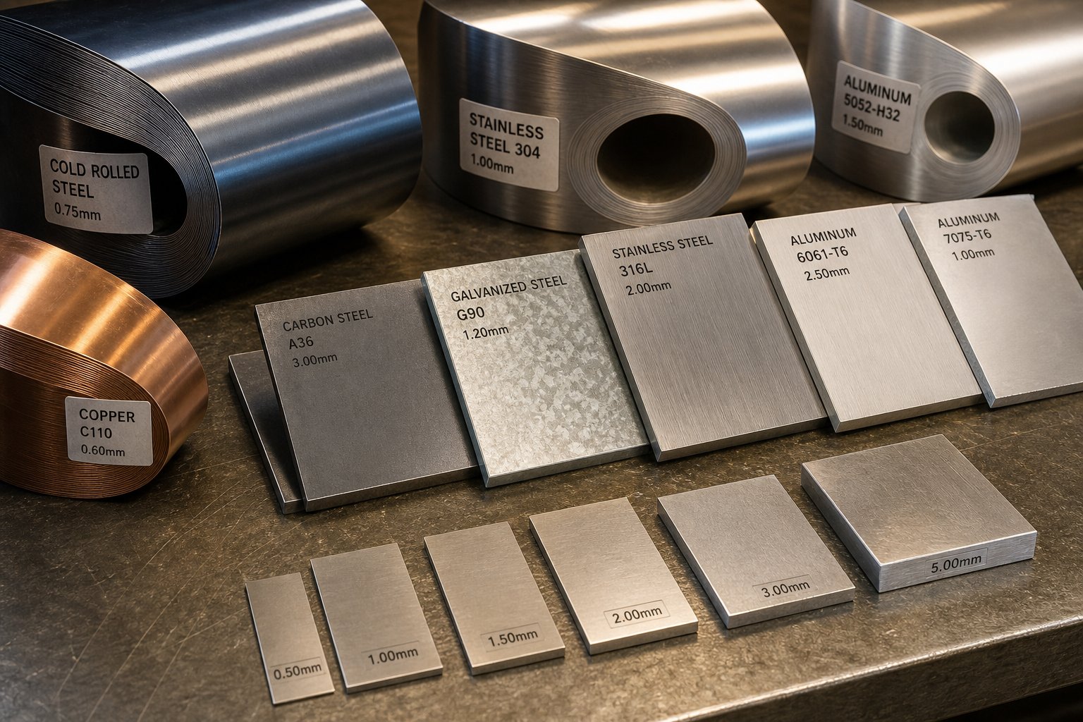
Most structural truck brackets and reinforcements rely on high-strength low-alloy (HSLA) steel grades specified under SAE J2340. Grades like 340X (340 MPa minimum yield) and 420X (420 MPa minimum yield) offer the strength-to-weight improvements truck OEMs need while remaining formable in progressive dies. Steel progressive stamping with these grades requires careful attention to springback - the material's elastic recovery after bending. HSLA steels spring back significantly more than mild steel, often requiring 2 to 4 degrees of overbend compensation built directly into the die geometry.
For crash-critical brackets - think cab mounting structures or B-pillar reinforcements - dual-phase (DP) steels such as DP590 and DP780 enter the conversation. These grades combine a soft ferrite matrix with hard martensite islands, delivering tensile strengths above 590 MPa while retaining enough elongation for moderate bending. The trade-off? Higher forming forces, accelerated punch wear, and increased snap-through shock that can chip die components. As The Fabricator notes, the harder the material, the less actual shearing occurs and the more it "breaks," increasing reverse shock loading through both die and press.
Galvanized (GI) and galvannealed (GA) sheets add corrosion protection for underbody and frame components. The zinc coating behaves differently in carbon steel progressive stamping: galvannealed coatings are harder and more prone to powdering during forming, while galvanized coatings are softer but can gall against die surfaces. Both require specific lubricants and tighter control of die surface finish to prevent coating damage.
Aluminum and Lightweight Alloys for Progressive Stamping
Weight reduction mandates are pushing aluminum progressive stamping into truck applications that were traditionally steel-only. Alloys like 5052-H32 (215 MPa yield, excellent formability) suit cab hardware and interior brackets, while 6061-T6 (275 MPa yield) handles structural roles where higher strength justifies the forming difficulty.
Aluminum behaves fundamentally differently in a progressive die than steel. It work-hardens faster, meaning each successive forming station encounters incrementally harder material. It also galls aggressively against tool steel surfaces without proper lubrication or die coatings. Dry-film lubricants and PVD coatings like TiN or CrN on die surfaces are standard practice for aluminum runs. Springback in aluminum is typically 1.5 to 2 times greater than equivalent-gauge mild steel, demanding more aggressive overbend angles and sometimes additional restrike stations.
How Material Properties Affect Die Wear and Maintenance
The stamping die steel you select for tooling inserts must match the work material's abrasiveness and forming demands. Harder sheet materials wear dies faster, shorten maintenance intervals, and increase total cost of ownership. Here is how common truck-part materials compare across the properties that matter most for progressive die performance:
| Material | Yield Strength (MPa) | Formability Rating | Springback Tendency | Recommended Die Steel |
|---|---|---|---|---|
| Mild Steel (SAE 1008/1010) | 170–210 | Excellent | Low | D2 or A2 tool steel |
| HSLA 340X (SAE J2340) | 340–400 | Good | Moderate | D2 with TiCN coating |
| HSLA 420X (SAE J2340) | 420–480 | Moderate | Moderate-High | M2 or PM tool steel |
| Dual-Phase DP590 | 340–590 (tensile) | Moderate | High | PM tool steel (CPM 10V) |
| Dual-Phase DP780 | 450–780 (tensile) | Low-Moderate | Very High | Carbide inserts at wear points |
| Galvannealed (GA) Steel | Varies by base | Good (coating powders) | Per base grade | Polished D2, low-friction coating |
| Aluminum 5052-H32 | 195–215 | Excellent | Moderate-High | D2 with TiN/CrN PVD coating |
| Aluminum 6061-T6 | 275–310 | Moderate | High | Carbide or ceramic-coated inserts |
Thickness drives press tonnage selection proportionally. A 1.5 mm HSLA bracket might require 150 tons across all active stations, while the same geometry in 4.0 mm gauge could demand 400 tons or more. Die clearance - the gap between punch and die opening - also scales with thickness. Typical clearance for steel stamping dies runs 6% to 10% of material thickness per side; aluminum needs tighter clearances (around 5% to 8%) to prevent excessive burr formation.
Matching material grade to the right stamping die steel pairing, lubrication strategy, and press capacity is what separates a die that runs a million hits without rework from one that chips punches at 50,000 cycles. These material behaviors also dictate the design rules engineers must follow when specifying part geometry - constraints the next section translates into actionable DFM guidelines.
Design for Manufacturability in Progressive Die Truck Parts
Material properties set the boundaries, but part geometry determines whether a progressive die design actually works - or burns through tooling budget on avoidable iterations. Design for Manufacturability (DFM) is where truck part engineers and stamping specialists align on what the metal can physically do inside a progressive stamping tool. Get this right early, and you shorten PPAP timelines, reduce die tryout cycles, and avoid the costly "build-test-fix" loop that delays production launches.
Engineering decisions made during the DFM phase dictate up to 80% of total production cost. That means the geometry you freeze into your CAD model has more influence on per-part economics than any downstream negotiation with a supplier.
Bend Radii and Draw Depth Limits for Truck-Gauge Materials
Truck brackets in the 2.0 mm to 6.0 mm range push forming limits that thinner consumer parts never encounter. The fundamental rule of progressive stamping die design for bends: internal bend radius should be equal to or greater than material thickness (R ≥ T). Drop below that threshold in HSLA or dual-phase steels and you risk micro-cracking at the bend apex, stress concentration failures in service, and premature punch wear.
Draw depth presents a harder constraint. Inside a progressive die, the part remains attached to the carrier strip throughout all forming stations. Deep draws stretch and thin the carrier connections, eventually tearing them. For truck-gauge steels, practical draw depth inside progressive die tooling tops out at roughly 1.0 to 1.5 times the strip width of the draw feature. Anything deeper typically needs a transfer die or a dedicated draw station with a separate blank holder - adding cost and complexity.
Here are the core DFM rules truck part engineers should follow when specifying geometry for a progressive stamping tool:
- Minimum bend radius: R ≥ 1.0T for HSLA steels; R ≥ 1.5T for dual-phase grades (DP590 and above) to prevent cracking.
- Hole-to-edge distance: Minimum 2.0T from any hole center to the nearest edge or formed feature. Closer placement distorts hole geometry during bending.
- Hole diameter minimums: At least 1.0T for round holes. Smaller piercings require specialty punches with shorter maintenance intervals.
- Draw depth limit: Keep formed depth below 1.5 times the feature width when possible. Exceeding this risks carrier strip tearing and part distortion.
- Grain direction orientation: Specify bends perpendicular to the rolling direction of the coil to reduce fracture risk at formed edges.
- Flat-to-form transitions: Include adequate relief notches at bend intersections to prevent material bunching and tearing.
Strip Layout Optimization and Carrier Design
The carrier strip is the backbone of every progressive tool and die operation - it physically connects each part to the next through all forming stations. For heavy-gauge truck parts, carrier design demands more attention than lighter-gauge work because thicker material resists the flexing needed to accommodate height differences between stations.
Two primary carrier types serve different purposes. A solid carrier works for parts with basic cutting and bending where the entire strip remains flat throughout the stroke. A stretch web carrier suits parts with deeper forming or embossing, allowing the metal to flow freely without shifting pitch distance between progressions. For truck brackets with moderate draw depths, stretch carriers prevent the positional errors that would otherwise accumulate across multiple stations.
Pilot hole placement ties directly into carrier reliability. Pilots should be positioned in stable, unformed sections of the strip - typically within the carrier web itself rather than inside the part boundary. This ensures registration accuracy stays consistent even as forming operations apply forces that could shift the strip laterally.
Strip width optimization affects both material cost and press selection. Wider strips accommodate larger truck brackets but demand presses with bigger bed dimensions. Where possible, nesting two smaller parts across the strip width improves material utilization and reduces scrap percentage - a direct cost lever in high-volume programs.
Reducing Station Count Through Geometry Simplification
Every additional station in a progressive die increases tooling cost, lengthens the die, and may require a larger press. Metal stamping die design that minimizes station count without sacrificing part function is where DFM delivers its biggest payoff.
Practical strategies include:
- Combine piercing operations: Group holes that share the same plane into a single station rather than spreading them across multiple hits.
- Eliminate cosmetic features that add stations: Embossed logos or decorative beads that require dedicated coining stations may not justify the tooling cost on non-visible structural parts.
- Simplify compound angles: A bracket with three separate bend angles in different planes needs three forming stations. Redesigning to two bends in a shared plane saves one full station.
- Integrate in-die secondary operations: Adding in-die tapping or hardware insertion eliminates downstream assembly steps and can reduce total lead time by up to 30%, even though it adds a station to the die.
These geometry trade-offs are exactly why early collaboration between OEM design engineers and progressive tool and die specialists produces better outcomes than handing off a frozen design for quoting. Stamping suppliers who bring DFM feedback into the design phase - before geometry is locked - help avoid costly tool revisions after hardened steel has been cut. As one example, YICHEN supports automotive OEM, Tier-1, and Tier-2 engineering teams with stamping process case studies and DFM feedback for structural, chassis, and truck-related metal parts, illustrating how supplier-side engineering input during the design stage shortens the path from concept to validated stamping die design.
The deeper lesson: a progressive die is a precision-hardened tool. Late-stage design changes can cost nearly half the original tooling investment in rework. Investing engineering time upfront - through simulation, DFM review, and collaborative geometry refinement - pays for itself many times over across a production run. That tooling investment, and the volumes needed to justify it, is precisely what the cost analysis ahead breaks down in detail.
Progressive Die Stamping vs. Transfer Dies and Alternative Methods
Choosing the right forming process is not about picking a favorite - it is about matching process capability to part requirements. A progressive die and stamping setup that delivers lowest cost on a cab mounting clip could be the wrong choice entirely for a large cross-member shell with deep draws. Truck OEM buyers and design engineers need a clear framework for deciding which method fits which part, without over-investing in tooling or under-delivering on geometry.
Progressive Die vs. Transfer Die for Truck Brackets
The most common comparison truck engineers face is progressive die versus transfer die stamping. Both use hardened steel tooling and high-tonnage presses, but they solve different problems.
Progressive dies keep the part attached to the carrier strip through all forming stations. That constraint limits part size to what fits within the strip width (typically under 600 mm) and keeps draw depth shallow. But the payoff is speed - no mechanical transfer mechanism means faster cycle times and fewer moving parts to maintain.
Transfer dies cut a blank from the strip first, then move it independently between stations using mechanical grippers or shuttle systems. This allows larger blanks, deeper draws, and more complex three-dimensional forming. A transfer die also reduces material usage because it eliminates the carrier web, saving material cost on every cycle. The trade-off? Slower throughput, higher tooling complexity, and longer setup times between production runs.
For truck brackets specifically: if the part fits on a strip, needs moderate forming, and runs above 100,000 pieces annually, progressive stamping wins on per-part cost. If the bracket exceeds strip width limits or requires draw depths beyond 1.5 times the feature width, transfer dies become necessary regardless of volume.
When CNC Machining or Compound Dies Make More Sense
Not every truck part warrants a stamping die at all. Two alternatives deserve evaluation before committing tooling dollars.
Compound die stamping completes multiple cutting operations - blanking and piercing - in a single press stroke. It produces flat parts with excellent dimensional accuracy and tighter tolerances than progressive methods can achieve on cut edges. For simple flat washers, shims, or gasket carriers that need only blanking and hole piercing without any forming, compound dies deliver precision at lower tooling cost. The limitation is clear: compound dies cannot bend, form, or draw. They handle two-dimensional geometry only.
CNC machining enters the picture when annual volumes are too low to justify any die stamping investment. Prototype brackets, low-volume specialty truck variants producing fewer than 5,000 parts per year, or parts requiring tolerances below ±0.05 mm on machined features all point toward CNC. The per-part cost is higher, but there is zero tooling lead time and complete design flexibility. For truck programs still iterating on geometry, machining buys time until the design freezes and volume justifies dies and stamping tooling.
Decision Matrix Based on Volume, Size, and Geometry
When you are evaluating supplier proposals or choosing between process paths for a new truck platform, the decision comes down to five variables. Here is how progressive, transfer, compound, and CNC methods compare across the criteria that matter most:
| Criteria | Progressive Die | Transfer Die | Compound Die | CNC Machining |
|---|---|---|---|---|
| Part Size Range | Small to medium (up to ~600 mm) | Medium to large (up to 1,200 mm+) | Small to medium (flat only) | Any size (fixture-limited) |
| Material Thickness | 0.5 mm to 6.0 mm | 0.8 mm to 12.0 mm | 0.3 mm to 6.0 mm | Any (plate or sheet) |
| Ideal Annual Volume | 100,000 to 5,000,000+ | 25,000 to 500,000 | 10,000 to 500,000 | 1 to 10,000 |
| Per-Part Cost at Scale | Lowest | Low-Moderate | Low (flat parts only) | Highest |
| Tooling Lead Time | 12 to 20 weeks | 14 to 24 weeks | 8 to 14 weeks | None (programming only) |
| Geometric Complexity | Moderate (bends, shallow forms, piercings) | High (deep draws, large forms, complex 3D) | Low (flat blanking and piercing only) | Very high (any machinable geometry) |
A few patterns emerge from this comparison. Progressive die stamping owns the high-volume, small-to-medium part space where per-part cost matters most. Transfer dies pick up where progressive hits its size and depth limits. Compound die stamping fills a niche for flat precision parts where forming is unnecessary. And CNC machining serves as the low-volume safety valve - expensive per piece, but zero commitment to hardened tooling.
For most truck programs, the answer is not one process but a portfolio. Frame rail brackets and cab clips run in progressive dies. Larger structural shells go to transfer presses. Prototype and pre-production quantities start on CNC until volumes justify the stamping die investment. Knowing where each method breaks even - and where it breaks down - is the foundation for building a tooling budget that holds up across the life of a truck platform.
Tooling Investment and Production Volume Break-Even Analysis
Knowing which process fits your part is half the equation. The other half is knowing when the numbers actually work in your favor. Progressive die tooling represents a significant upfront capital investment, but for truck programs with the right volume profile, it delivers the lowest achievable per-part cost over the life of the program. The key is understanding where your break-even point sits and what factors push it higher or lower.
Tooling Amortization and Break-Even Volume Thresholds
Progressive die tooling for truck parts typically ranges from $10,000 for simpler tools to $350,000 for complex multi-station dies, with most mid-complexity truck brackets falling in the $15,000 to $60,000 range. The math that makes long run metal stamping compelling is straightforward: a $30,000 die spread across 30,000 parts adds $1.00 per piece to your cost. Spread that same die across 300,000 parts and tooling contribution drops to $0.10. At one million cycles, it is essentially negligible.
For truck programs, the break-even threshold where progressive die stamping services become more cost-effective than laser cutting or press brake forming typically lands between 10,000 and 50,000 annual units, depending on part complexity and alternative process cost. High-volume Class 8 components running 200,000 or more pieces per year amortize tooling so quickly that the per-part economics are difficult to match with any other method. Specialty truck variants producing under 5,000 units annually rarely justify the investment unless parts carry over across multiple vehicle platforms.
Several factors influence where your specific break-even falls:
- Station count: Each additional station adds machining hours, die material, and tryout complexity. A 6-station die might cost $20,000; a 14-station die for the same part family could exceed $60,000.
- Material grade: Stamping HSLA or dual-phase steels requires premium die steels (PM grades, carbide inserts) that increase tooling cost 20% to 40% over mild-steel tooling.
- Tolerance demands: Tighter positional tolerances require more precise machining of die components and longer tryout validation, pushing up both initial cost and lead time.
- Expected die life: A tool designed for 500,000 hits uses different construction than one built for 5 million. Longer-life tooling costs more upfront but avoids mid-program rebuilds.
- Multi-part dies: Nesting two or more parts per stroke multiplies output without proportionally increasing tooling cost, improving break-even economics for smaller components.
In-Die Secondary Operations That Reduce Assembly Costs
Tooling investment does not exist in isolation - it competes against total landed cost, not just the stamping operation alone. One of the strongest economic arguments for progressive stamping and fabrication programs is the ability to integrate secondary operations directly inside the die. When you eliminate downstream handling, you eliminate downstream labor cost.
In-die operations commonly integrated into truck part progressive dies include:
- In-die tapping: Threads are cut or formed directly at a dedicated station, removing a separate tapping operation that would otherwise require fixturing and an additional operator.
- Hardware insertion: PEM clinch nuts, studs, or threaded inserts are pressed into the part during the stamping cycle. The part exits the die ready for bolt-up assembly.
- In-die welding: Resistance spot welding or projection welding attaches secondary components (nuts, brackets, studs) without leaving the press line.
- Contact sensing and measurement: In-die sensors verify critical dimensions in real time, diverting suspect parts before they enter the supply chain.
Each of these additions increases tooling complexity and upfront cost, but the payoff is a more complete part arriving at your assembly dock - fewer touch points, fewer quality escapes, and lower total labor per piece. For high speed progressive die stamping programs running hundreds of thousands of cycles, even a few cents saved per part in eliminated handling compounds into substantial annual savings.
Strip Utilization and Scrap Rate Optimization
Material cost is often the single largest variable expense in long run progressive stamping, so scrap management directly affects per-part economics. Progressive die metal stamping services providers optimize strip layout to extract maximum value from every meter of coil.
Strip utilization - the percentage of purchased material that ends up in finished parts rather than the scrap bin - typically ranges from 60% to 85% depending on part geometry. Smart nesting, minimized web widths between parts, and carrier designs that use as little material as possible all push utilization higher. A 5% improvement in material utilization on a program consuming 200 tons of HSLA steel annually translates to 10 tons of avoided material purchase - a real budget line item.
Die maintenance lifecycle costs round out the total investment picture. Industry estimates place annual maintenance at 5% to 10% of the die's original value, covering routine sharpening, shimming, punch replacement, and periodic inspection. Neglecting maintenance leads to burr formation, dimensional drift, and ultimately catastrophic die failure - all far more expensive than the scheduled upkeep. A well-maintained progressive die lasts millions of cycles, making it one of the longest-lived capital assets in a truck part supply chain.
The economics point clearly in one direction: once annual volume crosses the break-even threshold, progressive die stamping delivers cost performance that fabrication, machining, and even transfer pressing cannot match for small-to-medium truck parts. But cost without quality is a false economy - and the quality systems, tolerances, and supplier qualifications that protect your production investment deserve equally rigorous evaluation.
Quality Standards and Selecting the Right Truck Part Stamping Partner
A progressive die can deliver the lowest per-part cost in the industry - but only if every part that ships actually meets spec. Quality failures in truck components carry consequences that go far beyond scrap costs: field recalls, assembly line shutdowns, and lost platform awards. That is why truck OEMs hold their progressive die stampings suppliers to some of the most rigorous quality management standards in manufacturing. Understanding what those standards require - and knowing how to evaluate a stamping die supplier against them - protects your program from launch delays and production escapes.
IATF 16949 and PPAP Requirements for Truck Part Suppliers
IATF 16949:2016 is the baseline quality certification that truck OEMs and Tier-1 suppliers expect from any progressive die manufacturer bidding on production work. It builds on ISO 9001 but adds automotive-specific requirements for defect prevention, advanced product quality planning (APQP), and production part approval (PPAP). With over 65,000 certified suppliers worldwide, IATF 16949 is not a differentiator - it is a gate. Suppliers holding only ISO 9001 typically lack the documented PPAP capability, FMEA discipline, and SPC infrastructure that truck programs require.
PPAP submission levels define how much documentation a supplier provides before production approval. Truck OEMs commonly require Level 3 submissions, which include dimensional reports, material certifications, process flow diagrams, control plans, Gage R&R studies, and capability indices (Cpk) for critical characteristics. A qualified stamping die supplier delivers these packages quickly and completely - delays in PPAP documentation translate directly into delayed production launches.
Dimensional Tolerances Achievable in Progressive Die Stamping
What precision can you actually expect from a progressive die running truck-gauge HSLA steel? For critical features, precision die and stamping operations routinely hold ±0.05 mm on pierced holes and formed dimensions under controlled press conditions. Larger features in the 30 mm to 120 mm range typically achieve ±0.10 mm to ±0.15 mm, consistent with ISO 2768-1 fine class tolerances. These numbers assume a properly maintained metal stamping die, consistent material properties, and SPC-monitored production.
Maintaining those tolerances across a million-cycle run is where quality systems earn their value. Statistical Process Control (SPC) charts on critical dimensions detect drift before parts leave tolerance. In-die sensors monitor press force signatures every stroke, catching anomalies - a broken punch, a misfeed, a material thickness variation - within seconds rather than after thousands of defective parts have accumulated. High-speed vision inspection at the press outfeed performs 100% dimensional verification, rejecting suspect parts before they reach a shipping container.
Stamping die maintenance is the often-overlooked variable in long-term tolerance performance. Cutting edges dull, forming surfaces wear, and clearances open up gradually over hundreds of thousands of cycles. Progressive dies designed for long-term use can produce millions of parts over their service life - but only with scheduled preventive maintenance including edge regrinding, spring replacement, and clearance verification at defined stroke-count intervals.
Evaluating Stamping Supplier Capabilities for Truck Programs
When you are comparing progressive die manufacturers for a truck platform award, certifications are just the starting point. The deeper evaluation separates transactional shops from true engineering partners. Here is a supplier evaluation checklist that truck OEM procurement and engineering teams can reference during qualification:
- Quality certifications: Confirm IATF 16949 scope covers stamping, tooling, and any assembly operations relevant to your program. Verify certificates are current and audit findings are closed.
- PPAP track record: Request sample PPAP packages from prior automotive programs. Assess completeness, dimensional report clarity, and turnaround speed.
- Press fleet and tonnage range: Match available press capacity to your part's material thickness, strip width, and forming requirements. Confirm the supplier can scale volume without major tooling changes.
- In-house tooling capability: Verify that the supplier designs, builds, and maintains dies internally. Outsourced toolrooms add lead time risk, reduce accountability, and slow engineering changes.
- Material expertise: Evaluate experience with your specific material grade - HSLA, dual-phase, galvanized, or aluminum. Ask for documented capability studies on similar materials.
- SPC and inspection infrastructure: Confirm active SPC monitoring on press lines, CMM or equivalent dimensional equipment, and in-line vision systems for high-volume runs.
- Engineering support depth: Assess whether the supplier provides DFM feedback, forming simulation, and dedicated program engineering contacts - not just quoting and production. Suppliers like YICHEN, which supports OEM, Tier-1, and Tier-2 teams with stamping, fabrication, and process case studies for structural, chassis, and truck-related metal parts, exemplify the kind of engineering partnership that reduces program risk during launch.
- Preventive maintenance documentation: Review die maintenance logs for active programs. Consistent records indicate a culture of proactive quality; missing records signal reactive fire-fighting.
- Defect rate history: Request documented PPM data by part family. Prevention-based automotive stamping operations typically achieve 50 to 200 PPM defect rates.
A weighted scorecard across these criteria - weighting tooling capability and tolerance performance heavily for precision-critical truck parts - gives procurement teams an objective basis for comparing shortlisted progressive die manufacturers. The strongest candidates combine certified quality systems, in-house tooling control, material-specific forming expertise, and the engineering depth to collaborate on DFM before production begins. That combination is what keeps cost low and quality high across the full lifecycle of a truck platform.
Frequently Asked Questions About Progressive Die Stamping for Truck Parts
1. What types of truck parts are best suited for progressive die stamping?
Parts that work best in progressive dies share specific traits: flat or shallow-draw profiles, repeatable hole patterns, material thickness between 0.5 mm and 6.0 mm, and annual volumes above 50,000 units. Common examples include frame rail brackets, cross-member reinforcements, cab mounting clips, exhaust hangers, electrical connector housings, suspension mounting plates, and interior fastener clips. Parts that are poor candidates include deep-draw fuel tanks, oversized frame rails exceeding 600 mm strip width, and low-volume specialty components where tooling cost cannot be amortized effectively.
2. How much does progressive die tooling cost for truck components?
Progressive die tooling for truck parts typically ranges from $10,000 for simple tools to $350,000 for complex multi-station dies. Most mid-complexity truck brackets fall in the $15,000 to $60,000 range. The cost depends on station count, material grade (HSLA and dual-phase steels require premium die steels), tolerance requirements, expected die life, and whether in-die secondary operations like tapping or hardware insertion are included. Annual maintenance adds approximately 5% to 10% of the original tool value. Break-even versus alternative methods usually occurs between 10,000 and 50,000 annual units.
3. What is the difference between progressive die stamping and transfer die stamping?
Progressive dies keep the part attached to a carrier strip through all forming stations, limiting part size to roughly 600 mm and draw depth to shallow forms. They run faster and suit high-volume small-to-medium parts. Transfer dies cut the blank first and move it between stations with mechanical grippers, allowing larger blanks (up to 1,200 mm+), deeper draws, and complex 3D forming. Transfer dies also reduce material waste by eliminating the carrier web. Progressive dies are preferred when annual volumes exceed 100,000 units for parts within size limits; transfer dies handle larger or deeper-drawn components where progressive tooling cannot physically maintain carrier strip integrity.
4. What materials can be used in progressive die stamping for truck parts?
Common materials include mild steel (SAE 1008/1010), HSLA grades like 340X and 420X per SAE J2340, dual-phase steels (DP590, DP780) for crash-critical brackets, galvanized and galvannealed sheets for corrosion resistance, and aluminum alloys (5052-H32, 6061-T6) for weight reduction. Each material behaves differently in the die: HSLA steels require 2 to 4 degrees of springback compensation, dual-phase grades accelerate punch wear, aluminum galls against uncoated tool surfaces, and galvannealed coatings tend to powder during forming. Material choice directly affects press tonnage, die clearance, lubrication strategy, and maintenance intervals.
5. What quality certifications should a progressive die stamping supplier have for truck parts?
IATF 16949:2016 is the baseline certification truck OEMs expect, covering defect prevention, APQP, and PPAP capability. Suppliers should demonstrate Level 3 PPAP submission experience including dimensional reports, material certifications, process flow diagrams, control plans, and Cpk data. Beyond certifications, evaluate SPC monitoring infrastructure, CMM and in-line vision inspection systems, in-house tooling design and maintenance capability, and documented PPM defect rates (prevention-based operations typically achieve 50 to 200 PPM). Suppliers like YICHEN that offer engineering support for OEM and Tier-1 teams with process case studies represent the partnership model that reduces program risk during launch.


