


What High Speed Progressive Die Stamping Actually Means
When production engineers talk about running progressive dies faster, they often underestimate what separates a fast tool from a truly high speed operation. The difference is not just a matter of degree. It is a fundamentally different engineering challenge that changes how every component in the system must perform.
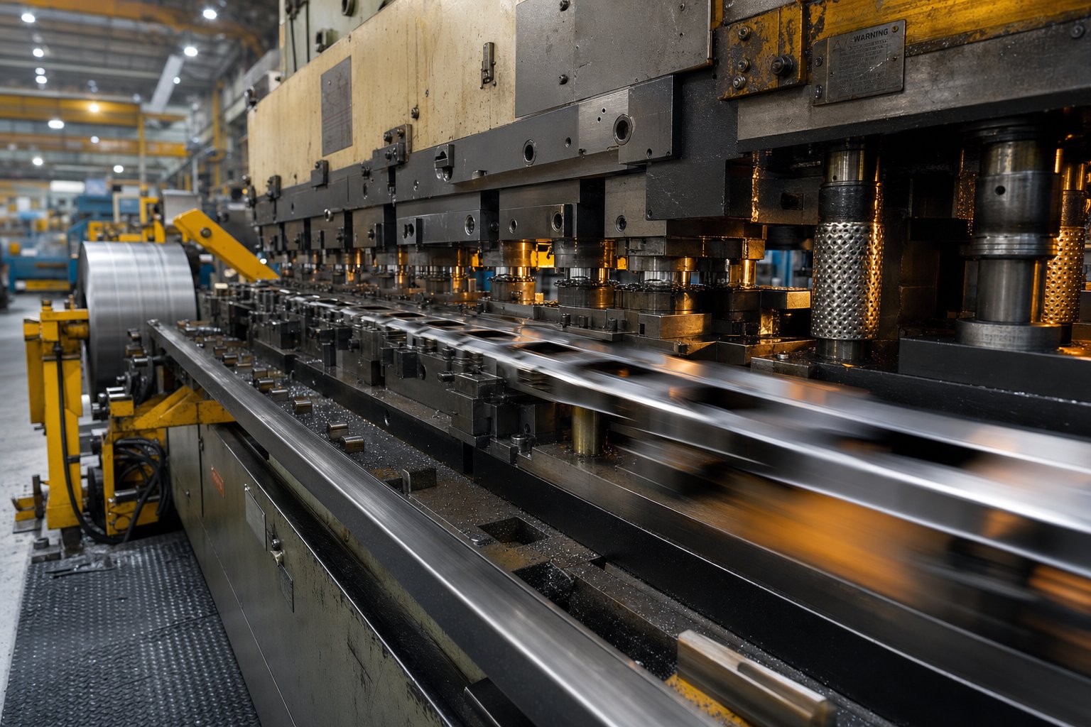
High speed progressive die stamping is a metal forming process in which a coiled strip advances through a series of die stations at press speeds of 800 to 1,800+ strokes per minute (SPM), producing a finished part with each stroke. Unlike standard progressive stamping, which operates below 400 SPM, high speed operation demands specialized press frames, feed systems, tooling materials, and strip designs engineered to maintain accuracy under extreme cycling rates.
What Qualifies as High Speed in Progressive Die Stamping
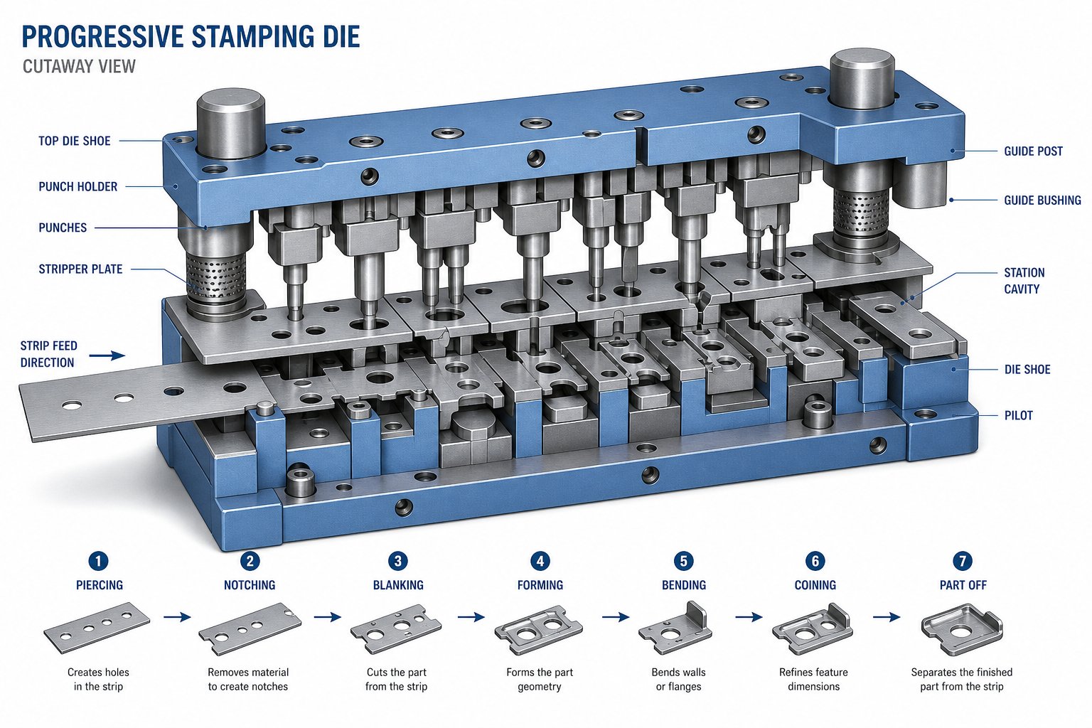
So what is a progressive die, exactly? Picture a single tool with multiple workstations arranged in sequence. A metal strip feeds through the stamping die, and each station performs one operation, whether that is piercing, forming, bending, or cutoff. With every press stroke, the strip advances and the part takes shape progressively until it is separated at the final station.
That concept applies at any speed. What qualifies a process as high speed progressive die stamping is the stroke rate itself. Industry sources note that progressive stamping dies for complex parts like electrical connectors can be designed to run at 1,200 to 1,500 SPM, with some applications pushing beyond 1,800 SPM. At those rates, a single press can produce over a million parts per shift.
Standard Speed vs High Speed Stroke Rates
Standard progressive stamping typically runs below 400 SPM. That range works well for larger parts, thicker materials, or geometries requiring significant strip lift between stations. High speed progressive stamping, by contrast, targets small-to-medium parts in thin-gauge materials where the physics allow rapid cycling.
Why does this distinction matter? Because speed changes everything. At 1,000+ SPM, carrier strips must resist buckling under intense acceleration forces. Pilot pins engage and disengage in milliseconds. Scrap slugs need to eject cleanly thousands of times per minute. Springs, strippers, and cams hit their mechanical limits. Every element of the stamping die, from punch geometry to feed timing, requires engineering decisions that simply do not apply at conventional speeds.
Engineers who treat high speed as just "running the press faster" discover the hard way that tooling designed for 300 SPM will not survive at 1,200 SPM. The requirements change at every level, and understanding that threshold is the first step toward getting the process right.
How the High Speed Progressive Stamping Process Works
Imagine a strip of metal entering a tool at rest and exiting as a finished part less than one-tenth of a second later. That is the reality of the progressive die stamping process at high speed. Every mechanical event, from coil feed to part ejection, happens in a tightly choreographed sequence where timing errors of even a few milliseconds can destroy tooling or halt production.
The progressive stamping process follows the same fundamental logic at any speed: a coiled metal strip advances station by station through a die, with each station performing a single operation. But at 800 to 1,800 SPM, the margin for error shrinks dramatically. Here is the step-by-step sequence from raw coil to finished component:
- Coil loading and uncoiling: The metal coil mounts on an uncoiler that pays out strip at a controlled rate, maintaining consistent tension without stretching the material.
- Straightening: The strip passes through a straightener that removes coil set (the natural curve from being wound) so it enters the die perfectly flat.
- Lubrication: A precision lubricator applies a controlled film to reduce friction and heat buildup at the die stations, which is critical when cycling rates generate significant thermal energy.
- Servo feeding: A feed mechanism advances the strip by a fixed distance (the feed pitch) with each press stroke, synchronized to the press crank angle.
- Pilot engagement: Pilot pins enter pre-pierced holes to correct any feed inaccuracy and lock the strip into exact position before the working stations engage.
- Station operations: The press stroke drives upper die components downward, and each station performs its assigned task: piercing, blanking, forming, coining, or bending.
- Scrap ejection: Punched slugs and trimmed waste drop through clearance holes in the die shoe or shed off the sides of the tool.
- Strip lift and advance: Lifters raise the strip clear of lower die details so it can advance freely to the next station on the following stroke.
- Final cutoff: The last station separates the completed part from the carrier strip.
- Part ejection and collection: Finished parts exit the die via chutes, air blasts, or conveyor systems for collection or downstream processing.
Every one of these steps must complete within a single press stroke cycle. At 1,200 SPM, that cycle lasts 50 milliseconds. You can see why progressive metal stamping at high speed demands a level of mechanical precision that goes far beyond standard tooling practice.
Station Sequencing and Strip Progression
Station sequencing determines the order in which the strip is pierced, formed, calibrated, and ultimately separated. Getting the sequence right is about more than making the part shape. It directly influences strip stability, tonnage balance, and whether the die can sustain high speed operation at all.
A practical rule in progressive die metal stamping: create pilot and datum features early, distribute heavy cutting loads across multiple stations, and leave three-dimensional forming until the strip has enough structural support from the carrier. The final cutoff always comes last, after any calibration or restrike operations.
At high speed, station count planning follows a specific principle: more stations performing simpler operations beat fewer stations handling complex ones. Splitting a heavy blanking operation across two stations, for example, reduces peak forces at any single point and minimizes the shock loading that destabilizes the strip at speed. This approach also reduces snap-through energy, which causes vibration and can bounce the strip off its intended path.
Feed pitch, the distance the strip advances per stroke, ties directly to speed capability. Shorter feed pitches mean less strip travel per cycle, which means the feed system has less work to do in less time. But you cannot shrink the pitch below the part's maximum developed envelope plus margin for scrap separation and pilot lead-in. The engineering tradeoff is clear: shorter pitch enables higher speed but can increase die complexity and limit part size.
Pilot Pins and Carrier Strip Design
Pilot pins provide the final positioning accuracy that makes progressive metal stamping repeatable at high speed. Early stations pierce pilot holes in the strip. As the strip advances, tapered pilot pins enter these holes before the working punches engage, correcting any feed error and locking the strip into position.
At conventional speeds, minor feed inaccuracies are manageable. At 1,000+ SPM, even small deviations accumulate into tolerance drift, mismatched trims, and progressive strip damage. Industry guidance places pilot-to-hole clearance at approximately 0.0005 to 0.001 inch for precision work. That tight fit is what corrects feeder error before it becomes a quality issue.
The carrier strip is equally critical. It holds and transports the partially formed part through the die until the final cutoff. Carrier design choices include single-side carriers, double-side carriers, center carriers, and ladder or tab configurations. The selection depends on part geometry, forming forces, and strip stability requirements.
At high speed, carriers face intense acceleration and deceleration forces with every stroke. A common guideline calls for carrier width of at least two times the material thickness, but geometry matters as much as width. If the carrier is too narrow or poorly supported, the strip can tip, buckle, or deform between stations. For parts that require significant forming, engineers often add stiffening beads or ribs in the carrier web to prevent flexing under dynamic loads. Some designs use a formed U-flange along the carrier edge to add rigidity without consuming extra strip width.
Scrap Management at High Throughput
Every pierced hole, trimmed edge, and slotted feature generates scrap. At 300 SPM, a stuck slug is an inconvenience. At 1,200 SPM, it is a die-crashing event that can happen so fast the operator has no time to react.
Slug pulling is the most common scrap-related failure at high speed. It occurs when a punched slug sticks to the punch face and gets pulled back up into the die cavity on the return stroke. The next time the strip advances, that slug is sitting where it does not belong, and the result is damaged tooling, scrap parts, or both. Thin materials and high-speed cycling increase slug-pulling risk because vacuum effects between the punch face and slug intensify at faster retraction speeds.
Reliable scrap management at high throughput requires planning during die design, not correction after problems surface in tryout. Effective strategies include:
- Straight, non-bridging drop paths through the die shoe for clean slug ejection
- Clearance holes sized to prevent slug stacking or jamming in the chute
- Mechanical anti-slug features such as slug shedders, retention buttons, or ejector pins
- Positive air blasts to push slugs clear of the die area
- Vacuum systems to pull slugs away from punch faces before retraction
Strip width optimization also plays a role in scrap management. Tighter strip layouts reduce material waste, which matters significantly at high volumes where even a millimeter of unnecessary width multiplies across millions of parts. The tradeoff: narrowing the strip too aggressively can starve the carrier of stiffness or leave insufficient web between features, leading to strip instability or edge cracking at speed. A practical balance puts aggressive nesting first, then verifies that bridges and carriers retain enough stiffness for reliable high speed transport.
The mechanical precision required for strip progression, pilot engagement, and scrap ejection at these cycling rates raises an obvious question: what kind of press and feed system can actually deliver this level of performance consistently?
Press and Feed Systems That Enable High Speed Stamping
A die designed for 1,200 SPM is only as capable as the press driving it and the feed system supplying it. Get either one wrong and you will never reach target speed, or worse, you will reach it briefly before something fails. The press and feed system form the mechanical foundation of any high speed metal stamping operation, and their specifications must be matched to each other and to the die.
Press Requirements for High Speed Operation
Not every mechanical press can run progressive dies at high speed. The physics of rapid cycling place specific demands on frame design, drive systems, and dynamic behavior that standard presses simply are not built to handle.
Frame rigidity and deflection control. A high-speed stamping press must maintain dimensional accuracy while cycling at extreme rates. Straight-side press frames with four to eight guideways provide the stiffness needed to resist deflection under off-center loading. Industry references note that C-frame presses are subject to higher deflection under off-center loads, making them poorly suited for precision progressive die work at speed. Tie-bar stiffness directly determines how much the frame "breathes" during each stroke. Even a few thousandths of an inch of frame deflection translates into tolerance drift on the stamped part, and at 1,000+ SPM those small errors repeat relentlessly.
Dynamic balancing. At conventional speeds, the reciprocating mass of the slide and upper die is manageable. At high speed, that mass generates violent inertial forces with every stroke reversal. Flywheel-driven progressive die press frames designed for high speed use dynamic counterbalancing, an opposing force that offsets the weight of the slide and upper die. Without it, the press would literally walk across the floor at ultrahigh speeds.
Short-stroke capability. High speed stamping presses keep stroke length as short as possible, typically around 2 inches or less. Shorter strokes mean less slide travel per cycle, which reduces acceleration forces and allows the press to reach higher SPM within its energy budget. The tradeoff is obvious: short strokes limit die shut height and strip lift clearance, so die design must accommodate these constraints.
Tonnage monitoring and snap-through control. Every blanking or piercing event produces a reverse load, called snap-through, as the punch breaks through the material. At high speed, snap-through energy multiplies because the press cannot dissipate it before the next stroke begins. Engineers must account for high reverse loads and press vibration when specifying high-speed stamping machines. Real-time tonnage monitoring per station detects force signatures that indicate punch wear, material variation, or slug pulling before they escalate into die damage.
Feed System Types and Speed Capabilities
The feed system must advance the strip by exactly the right amount, at exactly the right time, within a feed window that shrinks as press speed increases. Press feed fundamentals define the available feed window as the total press cycle time minus die engagement time minus misfeed detection time. At 1,200 SPM, the entire cycle lasts 50 milliseconds. The feed might have only 15 to 20 milliseconds to complete its index.
Three primary feed system types serve progressive stamping press applications, each with distinct speed capabilities and limitations:
Servo-driven roll feeds dominate high speed applications. They use closed-loop servo motors to control roll position with programmable acceleration profiles, including trapezoid, s-curve, and press-profile move patterns. Servo feed technology allows stampers to program different velocity curves depending on whether the priority is speed, surface finish, or strip stress management. Servo feeds also provide pilot release capability at high speed, either air-operated (limited to roughly 300 to 400 SPM) or servo-driven (fully programmable at very high speeds). Their ability to communicate with press controls, store job recipes, and self-diagnose issues makes them the standard choice for high speed metal stamping.
Press-driven roll feeds (mechanical feeds) are mechanically synchronized with the press crankshaft via rack-and-pinion or cam linkages. Because they draw power directly from the press, they can keep pace at very high speeds without the finite acceleration limits of a self-contained motor. They are well suited for dedicated high-speed applications. The drawbacks: feed length adjustment is cumbersome, they lack inching capability for setup, and they cannot interface with modern automation controls. For dedicated, single-purpose progressive die press lines running one part continuously, they remain viable.
Air-powered gripper feeds use linear clamping motion rather than rotary roll action. They are the least expensive option, but their return stroke consumes roughly half the available feed window, limiting maximum speed significantly. Compressed air response times add further latency. For high speed progressive stamping, gripper feeds are rarely appropriate.
| Feed System Type | Max Speed Capability | Positioning Precision | Material Thickness Range | Best Application |
|---|---|---|---|---|
| Servo-driven roll feed | 1,500+ SPM | ±0.001 in. or better | 0.003–0.250 in. | High speed progressive dies, flexible production |
| Press-driven roll feed | 1,800+ SPM | ±0.002 in. | 0.003–0.125 in. | Dedicated high-speed lines, single-purpose runs |
| Air-powered gripper feed | ~300 SPM | ±0.005 in. | 0.020–0.500 in. | Low to moderate speed, short feed lengths |
Servo feeds offer the best balance of speed, precision, and flexibility for most high speed stamping applications. Press-driven feeds can exceed servo speeds in dedicated setups, but their lack of programmability and setup flexibility limits them to long, unchanging production runs.
System-level optimization. Feed timing, press shut height, and die cushion pressure are not independent variables. They must be optimized together. The feed window narrows as speed increases, so feed start and end angles need precise calibration relative to die engagement. Shut height determines how deep the die closes, which affects strip lift clearance and the available window for strip advance. Die cushion systems, when used for forming or blank holding, add another timing variable because cushion response must keep pace with press cycling without introducing resonance.
When all three systems are tuned as an integrated unit, the result is a progressive stamping press that can sustain high speed operation reliably shift after shift. Get one element out of sync, even by a few degrees of crank angle, and the system develops feed faults, misfires pilot release, or crashes tooling.
The press and feed hardware sets the speed ceiling. But reaching that ceiling consistently depends on how the die itself is designed to operate within those constraints, particularly how station count, tooling materials, and strip layout decisions account for forces and wear patterns unique to high speed cycling.
Die Design Principles for High Speed Applications
A press capable of 1,500 SPM means nothing if the die inside it cannot sustain those speeds without degrading part quality or destroying itself. Progressive die design for high speed work follows a different philosophy than standard-speed tooling. The forces are larger, the timing windows are tighter, and small design oversights that are forgivable at 300 SPM become catastrophic failures at four times that rate.
Station Count Planning for High Speed Dies
Here is a principle that trips up engineers coming from standard-speed work: at high speed, more stations are better, not fewer. The instinct to consolidate operations into fewer stations to save die space works against you when cycling rates climb.
Why? Distributing work across additional stations reduces peak forces at any single point in the press stroke. Lower individual station forces mean less snap-through energy, less strip deflection, and less shock transmitted to the die frame. A detailed analysis of progressive die stability confirms that separating high-load operations like piercing, coining, and forming across multiple stations improves punch life, force distribution, and long-run dimensional control.
The practical math works like this. Progression distance (feed pitch) multiplied by total station count determines overall die length. At high speed, shorter progression distances are preferred because they reduce the feed system's workload within the compressed cycle time. But you cannot shrink pitch below the part's developed envelope plus clearance for scrap bridges, pilot lead-in, and carrier integrity. So the tradeoff becomes: accept a longer die with more stations doing simpler work, or try to cram operations into fewer stations and risk strip instability at speed.
Experienced progressive stamping die design also includes empty stations deliberately placed between heavy operations. These idle stations serve multiple purposes: they allow the strip to stabilize after a high-force event, provide space for future engineering revisions, and enable sensor integration for in-process monitoring. Skipping them to save cost is a common mistake that engineers regret once they hit production issues at speed.
Tooling Materials and Wear Considerations
At standard speeds, conventional tool steels like D2 or A2 provide acceptable punch and die life. At high speed, the calculus shifts dramatically. Every punch engages the strip over a thousand times per minute, and wear compounds faster than cycle count alone would suggest because heat buildup accelerates material degradation.
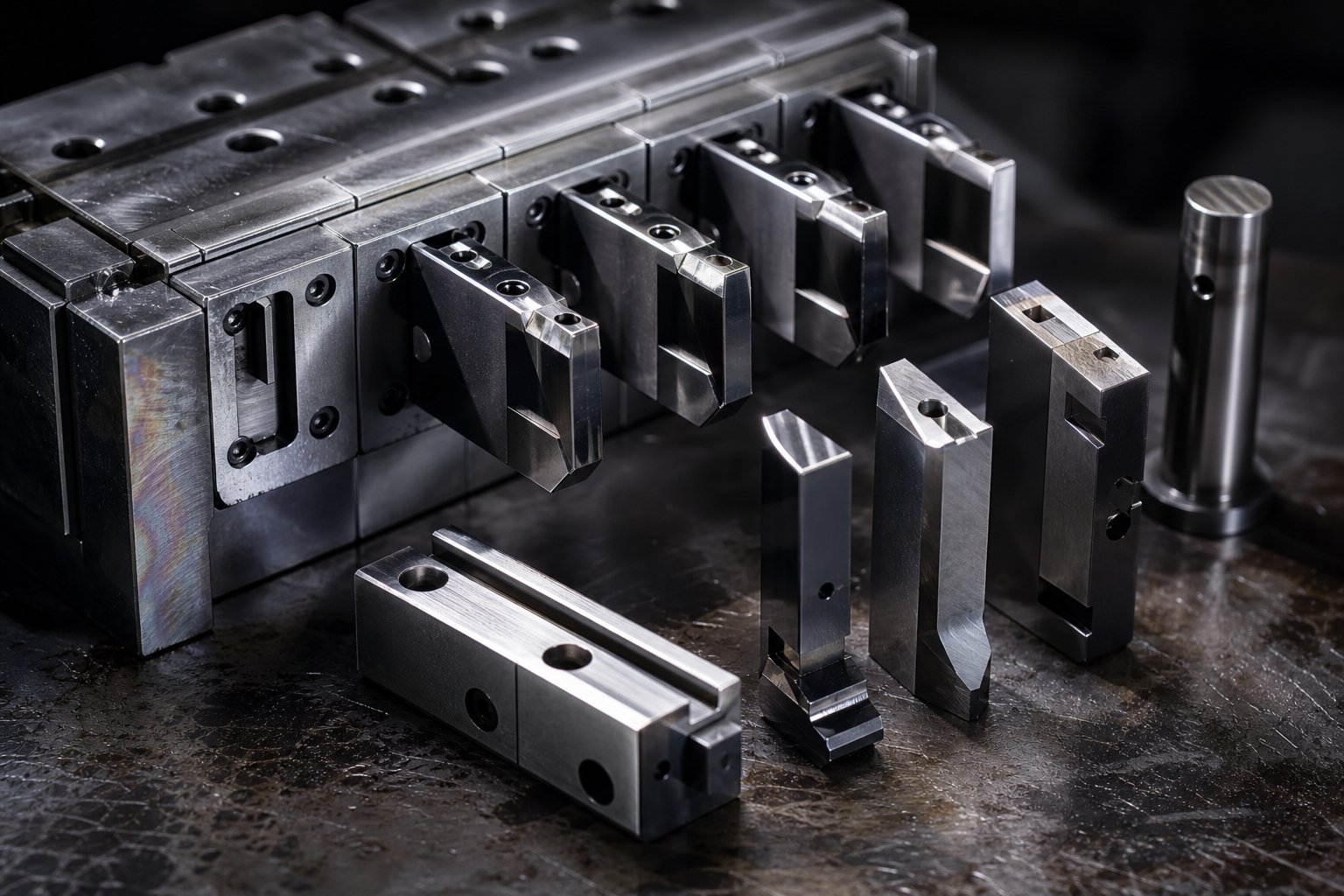
Tungsten carbide inserts are the standard for critical stamping die components in high speed progressive die tooling. Material selection research highlights carbide's advantages: superior wear resistance, dimensional stability under thermal cycling, and resistance to galling that keeps cutting edges sharp over millions of strokes. For less demanding stations, high-speed tool steels (M2, M4) with advanced coatings like titanium nitride (TiN) or diamond-like carbon (DLC) offer a cost-effective middle ground.
Punch geometry requires specific attention at high speed. Shear angles that work at conventional rates may generate unacceptable snap-through forces when multiplied by rapid cycling. Many high speed dies use staggered punch heights, offsetting cutting punches by small increments so they do not all break through the material simultaneously. This spreads the peak load across several degrees of crank rotation, reducing press shock and extending punch life.
Cutting clearances also behave differently at speed. Tighter clearances produce cleaner edges but increase stripping forces and heat generation. At high cycling rates, that heat has less time to dissipate between strokes. Clearances for high speed work are typically optimized slightly larger than textbook values for standard operations, balancing edge quality against thermal management and stripping reliability. Insufficient clearance at speed causes galling, burr growth, and premature punch failure.
Strip Layout Optimization Strategies
Strip layout is where metal stamping die design either enables or limits high speed capability. Every decision about part orientation, carrier configuration, and scrap bridge placement affects how the strip behaves under dynamic loading.
Progressive die design software plays a critical role here. Modern CAD/CAE tools simulate strip behavior through the entire progression sequence, predicting how material will flow, where stresses concentrate, and where carriers are at risk of buckling under feed acceleration. Engineers use these simulations to identify weak carrier sections, unbalanced pressure centers, and scrap evacuation problems before any steel is cut. Running these analyses is not optional for a high speed progressive stamping die. It is how you avoid discovering strip instability problems during tryout, when changes become expensive.
A few strip layout principles specific to high speed work:
- Keep carrier sections as short and wide as practical to resist buckling under dynamic feed forces
- Balance trim operations on both sides of the strip to prevent progressive camber from uneven stress release
- Position heavy piercing operations near the die center to minimize off-center loading
- Orient the part so that grain direction supports critical forming operations, even if it sacrifices a small percentage of material utilization
- Account for thermal expansion in clearance calculations, since rapid cycling raises die temperature 20 to 40 degrees Fahrenheit above ambient
That last point catches engineers off guard. At 1,200 SPM, friction and plastic deformation generate substantial heat that accumulates faster than it dissipates. Die components expand, clearances tighten, and interference fits that were fine at room temperature become problematic after 30 minutes of continuous running. Stamping die design for high speed must include thermal compensation, either through slightly enlarged initial clearances, engineered cooling channels, or both.
All these design decisions assume a specific material running through the die. But material behavior itself changes at high strain rates, and those changes create a separate set of constraints that engineers need to account for before finalizing any progressive die tooling design.
Materials and Thickness Limits in High Speed Stamping
Metal does not behave the same way at 1,200 SPM as it does at 300 SPM. The material itself changes its response when deformed at high strain rates, and those changes ripple through every aspect of die design, from clearance calculations to springback compensation. Engineers who select progressive stamping materials based solely on static data sheets are building their process on assumptions that break down at speed.
Material Behavior at High Strain Rates
When a punch strikes a strip at high speed, the material experiences strain rates far exceeding those in conventional stamping. What happens physically? The metal's yield strength increases, its elongation decreases, and its springback behavior shifts in ways that standard material property tables do not capture.
Think of it this way. At slow forming speeds, the crystal structure of the metal has time to accommodate deformation through dislocation movement. At high strain rates, dislocations pile up faster than they can redistribute, which raises the effective yield strength. Research on dual-phase steels demonstrates that increasing strain rate dramatically increases both the yield locus and springback behavior, even without temperature changes. The practical consequence: a bend angle that produces a 90-degree part at 200 SPM may produce an 87-degree part at 1,200 SPM because the material springs back further when deformed rapidly.
Reduced elongation at high strain rates also means the material is more brittle during forming. Features that form cleanly at standard speed, like tight-radius bends or deep draws, may crack or tear when the same geometry is produced at high speed. You cannot simply run a proven low-speed part design at quadruple the stroke rate and expect identical results. The material is effectively a different alloy at different speeds.
These strain-rate effects vary by material type. Carbon steel progressive stamping shows moderate sensitivity, with yield strength increasing roughly 10 to 20 percent at high strain rates. Copper progressive stamping and brass progressive stamping exhibit lower rate sensitivity, making these alloys more forgiving at speed. Aluminum progressive stamping presents a mixed picture: while the base metal has low rate sensitivity, the reduced elongation at speed makes tight forming features risky without additional compensation.
Thickness Limitations and Speed Tradeoffs
There is a practical thickness window for high speed progressive die stamping, and it is narrower than many engineers expect. The sweet spot runs from approximately 0.003 inch to 0.125 inch. Outside that range, physics starts working against you.
Why the lower limit? Below 0.003 inch, strip material becomes difficult to control mechanically. It lacks stiffness for reliable carrier transport, tends to flutter between stations, and can buckle under feed acceleration. Pilot engagement becomes unreliable because the material deforms too easily around pilot pins.
Why the upper limit? Thicker materials require more tonnage per piercing and forming operation, which generates greater snap-through forces and press shock at speed. The strip itself is heavier, so feed system acceleration demands increase. Scrap slugs from thicker materials are heavier and harder to eject cleanly at high cycling rates. And thicker stock generates more heat during cutting, accelerating punch wear. The result: as material thickness increases beyond 0.125 inch, maximum sustainable press speed drops rapidly.
The relationship is not linear. Doubling thickness from 0.060 inch to 0.120 inch might cut your achievable speed by 40 to 60 percent, depending on the material's shear strength and the die's station configuration. Engineers must treat thickness as a speed-limiting variable during process planning, not just a dimensional input.
| Material | Max Practical Speed (SPM) | Typical Thickness Range | Key Forming Considerations |
|---|---|---|---|
| Carbon Steel (low carbon, CRS) | 800–1,500 | 0.005–0.125 in. | Moderate springback at speed; higher snap-through forces require staggered punches; overbend or restrike for angular accuracy |
| Stainless Steel (300 series) | 600–1,200 | 0.005–0.080 in. | Work hardens rapidly; increased punch wear; requires carbide tooling and higher tonnage allowance; stainless steel progressive stamping demands tighter clearance control |
| Copper (C110, C102) | 1,000–1,800 | 0.003–0.060 in. | Low rate sensitivity; soft material increases slug-pulling risk; burr control critical for electrical contacts; galling on punch faces without proper coating |
| Brass (C260, C270) | 1,000–1,600 | 0.005–0.080 in. | Good formability at speed; stress-crack risk in aggressive bends; brass progressive stamping benefits from anneal between heavy-draw operations |
| Aluminum (1100, 3003, 5052) | 800–1,400 | 0.005–0.100 in. | Low rate sensitivity but reduced elongation at speed; scratching risk requires polished tooling; adhesive wear (galling) is primary failure mode without proper lubrication |
Notice the pattern. Softer, more ductile materials like copper and brass tolerate higher speeds across their thickness ranges. Harder alloys like stainless steel impose lower speed ceilings because they demand more force per operation and wear tooling faster. Material hardness directly correlates with die wear rate: a 300-series stainless at 62 HRB will consume punch edges roughly three to four times faster than soft copper at the same cycling rate.
Tensile strength compounds the issue. Higher-tensile materials generate greater snap-through forces, which not only stress the press frame but also accelerate fatigue in stripper springs, cam followers, and other stamping die components that cycle with every stroke. An engineer running stainless steel progressive stamping at 1,000 SPM should budget for sharpening intervals roughly half those of a comparable carbon steel application.
Coil quality becomes a gatekeeper at high speed. At 200 SPM, a feed system can compensate for moderate camber, thickness variation, or rough edge conditions. At 1,200 SPM, there is no time for compensation. MetalForming Magazine details how camber, the lateral curvature of a coil's edge, causes great difficulty in keeping the strip centered in the die during feeding, potentially making feeding impossible in severe cases. In high speed operations, even camber within standard ASTM tolerances can cause progressive misregistration that accumulates over a few dozen strokes into a misfeed event.
Thickness variation across the coil width is equally problematic. A strip that varies by plus or minus 0.001 inch may produce acceptable parts at standard speed. At high speed, that same variation causes inconsistent stripping forces, uneven pilot engagement, and fluctuating tonnage signatures that trigger false alarms on monitoring systems or, worse, go undetected until parts drift out of tolerance.
Edge condition matters too. Coils with slit edges carry shear/fracture profiles that differ from one side to the other. Unbalanced edge conditions can induce camber during stamping operations themselves, even when the incoming coil tests clean. For high speed progressive stamping, purchase specifications should tighten camber, thickness tolerance, and edge condition limits well beyond standard industry tolerances. The incremental cost of premium coil stock is trivial compared to the downtime and scrap that marginal material produces at speed.
Material selection and coil quality define what the die encounters on every single stroke. But producing parts accurately at speed is only half the challenge. The other half is knowing whether those parts are actually good, which requires quality control systems engineered for inspection rates that traditional methods cannot begin to match.

Quality Control Methods for High Speed Production
When a press produces 1,200 parts per minute, you cannot pull samples and measure them with a caliper. Traditional inspection, where an operator checks every tenth or hundredth part against a print, collapses completely at high speed progressive die stamping rates. The parts come too fast, the defects propagate too quickly, and by the time a human spots a problem, thousands of nonconforming pieces have already stacked up in the bin.
High precision metal stamping at these speeds demands quality systems that operate at machine tempo, detecting and responding to process drift in real time rather than after the fact. The solution is not more inspectors. It is a layered approach combining in-die sensing, automated vision inspection, and statistical process control that together provide continuous surveillance without slowing production.
In-Die Sensing and Real-Time Monitoring
In-die sensors are the first line of defense for progressive die stampings produced at high speed. These devices mount directly inside the tool and monitor critical process parameters on every single stroke, flagging deviations before they escalate into scrap or die damage.
Here is the challenge that makes in-die sensing tricky at speed. At 1,000 strokes per minute or more, it is virtually impossible to stop the press in time without making another hit due to ram inertia and effective stopping distance. Even if you signal the press to stop at 10 degrees past top dead center, the ram will likely reach bottom dead center and complete one additional stroke before halting. The goal shifts from preventing a single bad part to stopping the press before a second bad hit causes actual tool damage.
Several sensor types work together to provide comprehensive monitoring inside the die:
Proximity sensors are the most common type. They detect the presence or absence of features: a punched slug that failed to eject, a strip that did not advance fully, or a broken punch that is no longer in position. Pass-through proximity sensors reliably sense part ejection at the final cutoff station.
Micron sensors measure the distance between two surfaces with accuracy better than 0.00005 inch. They can detect slug packing in die cavities, material thickness changes, and stripper plate position anomalies. If anything obstructs the die from fully closing to its set point, the sensor halts the press. These sensors are not speed-sensitive, making them well suited for high-speed applications.
Load sensors mounted on press columns track stamping force with each cycle. Research published in the Journal of Manufacturing and Materials Processing confirms a direct, non-linear relationship between applied stamping force and part geometry, meaning force signatures can serve as real-time indicators of dimensional quality. A force curve that deviates from its established envelope signals punch wear, material variation, or tool misalignment before the parts themselves show visible defects.
Strip position sensors (eddy current type) verify the actual position of the stripper plate and strip relative to the die. In a properly functioning tool, the stripper clamps the material before working stations engage and maintains position through bottom dead center. Any deviation in stripper position correlates to changes in part quality, specifically bending angles and dimensional accuracy.
A practical caution from experienced toolmakers: while sensors in progressive dies are valuable, too many can generate disproportional false readings and production stoppages. When false alarms become routine, operators develop the habit of just resetting sensors rather than investigating real problems. Creativity in sensor placement matters. One well-positioned sensor can often detect multiple failure modes.
The critical monitoring parameters for high volume stampings at speed include:
- Tonnage signature per station: Tracks force curves across the press stroke, detecting punch wear, slug pulling, material variation, and overloading
- Strip feed accuracy: Confirms the strip advanced the correct distance before the working stations engage, catching misfeeds before they damage tooling
- Part presence detection: Verifies that each finished part has ejected from the die before the next stroke, preventing double-hits
- Die temperature: Monitors thermal buildup from rapid cycling, which affects clearances, lubrication film integrity, and dimensional stability
- Lubrication flow rate: Confirms that lubricant is reaching all critical stations, since dry spots at high speed cause immediate galling and punch failure
- Stripper plate position: Detects slug packing, broken springs, or material thickness anomalies that affect clamping behavior
Vision Systems and SPC at High Throughput
In-die sensors tell you the process is behaving normally. Vision systems confirm that the parts themselves meet dimensional requirements. These two approaches complement each other: sensors catch process faults in real time, while vision inspection provides direct dimensional verification of the output.
For high-speed lines exceeding 1,000 parts per minute, high-frame-rate CMOS sensors with hardware-triggered strobes synchronize image capture to the press stroke. These systems do not inspect every single part. Instead, they sample at a rate sufficient to detect drift, typically every 5th to 20th part depending on the application's tolerance requirements and historical process stability. Each inspection event is timestamped and linked to production data for full traceability.
Dimensional measurement at speed uses a combination of 2D area-scan imaging for profile verification and, where required, laser triangulation or structured light for height and flatness checks. Decision output latency for inline inspection typically falls between 50 and 500 milliseconds, which is fast enough to trigger rejection actuators before suspect parts mix with conforming ones in the collection system.
Statistical process control ties the entire quality system together. When you are producing thousands of parts per hour, SPC is not a reporting exercise. It is an operational tool that drives real-time decisions. Control charts running on continuous tonnage data, feed position accuracy, and sampled dimensional measurements detect trends before they reach control limits. Imagine the force signature on station four creeping upward by half a percent per hour. That trend means punch wear is progressing, and SPC data can predict when sharpening will be needed, days before the parts actually go out of tolerance.
This is where precision die stamping quality assurance gets practical. SPC-driven preventive maintenance scheduling replaces calendar-based or stroke-count-based sharpening intervals with condition-based triggers. The die gets serviced when the data says it needs service, not on a fixed schedule that may be too early (wasting uptime) or too late (producing scrap).
Tolerance capabilities at high speed follow a predictable pattern. At 400 to 800 SPM, well-maintained progressive dies hold blanked dimensions to plus or minus 0.001 inch and formed features to plus or minus 0.002 inch. As speed increases past 1,000 SPM, achievable tolerances widen slightly, typically to plus or minus 0.0015 inch on blanked features and plus or minus 0.003 inch on formed angles. The relaxation is not dramatic, but it is real, and it stems from increased dynamic forces, thermal effects, and the reduced time available for pilot correction. Engineers specifying precision die stamping tolerances at high speed need to account for this relationship between speed and achievable accuracy, communicating realistic capabilities to their design teams rather than quoting standard-speed tolerances that the process cannot sustain.
These quality control systems generate data. Lots of it. The question is what you do with that information when it comes time to choose between process alternatives or evaluate whether high speed progressive stamping is even the right method for a given part.
Choosing High Speed Progressive Stamping Over Alternatives
Knowing how to run high speed progressive dies and verify their output is one thing. Knowing whether you should be running a progressive die at all is a different question entirely, and the one engineers get wrong more often. A perfectly optimized progressive tool and die setup producing a part that would have been cheaper and simpler on a transfer press is still a failure of engineering judgment.
The decision between process types comes down to five factors: annual volume, part geometry, material thickness, tolerance requirements, and total cost at production scale. Get any one of these wrong and you either overspend on tooling for a process you did not need, or undersupply your production line with a method that cannot keep pace.
Progressive Die vs Transfer Die vs Compound Die
Each die stamping method handles parts differently during production, and that fundamental difference determines what each process does well and where it falls short.
In progressive stamping, the part stays connected to a carrier strip throughout the forming sequence. This strip connection is what enables extreme speed, but it also limits draw depth and restricts forming directions. You cannot flip a part, deep-draw a cup, or add features on the bottom surface while it remains attached to a strip.
Transfer die stamping separates the part from the strip early and moves it between stations using mechanical fingers or transfer rails. That freedom makes deep draws, multi-directional forming, and complex three-dimensional geometries possible. The tradeoff is speed. Transfer timing and mechanical reset between stations limits cycling rates to moderate SPM ranges, typically 40 to 150 SPM for complex work.
Compound die stamping completes all cutting operations in a single press stroke at one station. It produces flat parts with excellent edge quality and flatness because there is no cumulative deformation from multiple stations. But it handles only simple geometries: washers, shims, flat electrical contacts, and similar two-dimensional shapes. No forming, no bending, no progressive complexity.
Here is the comparison that matters for process selection:
| Criteria | High Speed Progressive Die | Transfer Die | Compound Die | Fourslide / Multislide |
|---|---|---|---|---|
| Ideal Annual Volume | 500,000 to 100+ million | 25,000 to 1,000,000 | 10,000 to 500,000 | 10,000 to 5,000,000 |
| Part Complexity | Moderate (2D and limited 3D forming) | High (deep draws, multi-direction) | Low (flat profiles only) | High (multi-axis bends, complex springs) |
| Material Thickness Range | 0.003–0.125 in. | 0.020–0.500 in. | 0.010–0.250 in. | 0.005–0.080 in. |
| Typical Speed (SPM) | 800–1,800+ | 40–150 | 100–400 | 100–500 |
| Tooling Cost | $30,000–$250,000+ | $50,000–$300,000+ | $5,000–$40,000 | $3,000–$25,000 |
| Piece Price at Volume | Lowest | Moderate | Moderate | Low to moderate |
| Deep Draw Capability | Limited by strip tension | Excellent | None | None |
| Secondary Operations Needed | Sometimes (tapping, plating, assembly) | Rarely | Often (forming, bending) | Rarely |
The volume threshold is the first filter. Economic analysis shows progressive die stamping becomes cost-effective starting around 50,000 units annually for simple parts, but high speed progressive stamping really justifies its investment at 500,000 or more pieces per year. Below that, the tooling cost amortizes too slowly and simpler processes win on total economics.
Part geometry is the second filter. If your part requires deep draws exceeding 1.5 times material thickness, multi-directional forming, or features on both sides that cannot be created from a strip-fed approach, transfer die stamping is the appropriate method regardless of volume. Forcing a deep-draw geometry into a progressive tool adds stations, reduces strip stability, and often still requires secondary forming operations that erase the speed advantage.
For flat, two-dimensional parts at moderate volumes, compound die stamping offers the simplest and most cost-effective path. The tooling is less expensive, lead times are shorter, and the single-stroke process delivers excellent flatness. There is no reason to invest in progressive tool and die complexity for a part that can be completed in one hit.
When Fourslide Machines Are a Better Fit
Fourslide and multislide machines occupy a niche that progressive dies handle poorly: parts requiring complex multi-axis bending from strip or wire, especially springs, clips, brackets, and formed contacts with tight bend radii in multiple planes.
Where a progressive die forms bends using vertical press motion and cam-driven side actions, fourslide machines use four or more horizontal slides to shape metal from multiple angles simultaneously. This approach produces multi-dimensional parts with complex geometries that would require expensive cam systems or secondary operations in a progressive die.
Fourslide tooling costs are a fraction of progressive die investment, often $3,000 to $25,000 versus $50,000 or more for comparable progressive stage tooling. Setup flexibility is also better: changing a bend angle on a fourslide is a matter of adjusting a cam, while the same change on a progressive die may require grinding and welding die steel.
The limitations are real, though. Fourslides handle thin materials only, typically under 0.080 inch. Part size is constrained. And while capable of 100 to 500 SPM, they cannot match the raw throughput of a dedicated high speed progressive press at 1,200+ SPM. If your annual volume exceeds several million pieces and the geometry can be produced from a strip without multi-axis slide action, progressive stamping wins on piece price.
The honest engineering answer: no single process dominates across all part geometries and volumes. High speed progressive die stamping delivers unmatched cost efficiency for small-to-medium parts in thin gauge materials at very high volumes. Transfer dies handle what progressive cannot form. Compound dies simplify what progressive would overcomplicate. Fourslides bend what progressive dies struggle to reach. Match the process to the part, not the other way around.
Once you have confirmed that progressive stamping is the right fit for your application, the focus shifts to keeping those dies running productively over millions of cycles and identifying suppliers who can build and maintain tooling at the level high speed production demands.
Die Maintenance and Supplier Selection for High Volume Runs
A progressive die designed for 1,200 SPM might survive tryout perfectly and produce flawless parts for the first 50,000 hits. Then reality sets in. Wear patterns at high speed are not simply accelerated versions of standard-speed degradation. They are qualitatively different, driven by thermal cycling, dynamic stress concentrations, and lubricant film failures that do not occur at conventional rates. Engineers who apply standard-speed maintenance schedules to high speed tooling discover that their dies degrade faster than predicted, scrap rates creep upward between service intervals, and unplanned downtime eats into the throughput advantage they invested in.
The other half of the equation is equally critical: finding progressive die manufacturers who understand these demands and can build tooling that sustains high speed operation over millions of cycles. Stamping die maintenance and supplier capability are inseparable concerns for any production engineer running high volume progressive stamping.
Die Maintenance and Tool Life at Speed
At 300 SPM, a well-built punch might last 500,000 to 1,000,000 hits between sharpenings. At 1,200 SPM, that same punch geometry and material can degrade in a fraction of the cycle count, not because it is seeing more total strokes per sharpening interval, but because the conditions at each stroke are harsher. Three wear mechanisms accelerate disproportionately at high speed:
Accelerated punch wear. Cutting edges experience higher temperatures at speed because heat generated during shearing has less time to dissipate before the next stroke arrives. This thermal cycling softens tool steel surfaces, promotes micro-cracking at cutting edges, and accelerates abrasive wear. Industry maintenance guidance identifies worn cutting edges, chips, and cracking as primary indicators that sharpening or replacement is overdue. At high speed, these indicators develop in days rather than weeks.
Stripper plate fatigue. The stripper assembly cycles with every press stroke, clamping and releasing the strip material over a thousand times per minute. Springs fatigue faster, guide pins develop play sooner, and the plate itself can develop micro-distortions from repeated impact loading. Preventive maintenance research recommends replacing springs when free length drops by more than 10 percent or when cracking appears, but at high speed cycling rates, spring degradation curves compress significantly.
Lubricant breakdown. Stamping lubricants maintain a film between punch surfaces and strip material that prevents galling and reduces heat. At high cycling rates, the combination of elevated temperature and reduced re-application time between strokes causes lubricant film failure. Once the film breaks down, metal-to-metal contact produces galling almost immediately. Lubricant delivery systems must apply product at rates matched to press speed, not at fixed intervals designed for slower operation.
These three factors compound each other. A punch running slightly dull generates more heat, which degrades lubricant faster, which accelerates wear further. The failure cascade happens quickly at speed, which is why reactive maintenance, waiting until parts show visible defects, is a losing strategy for high speed progressive tooling.
Sharpening intervals and preventive scheduling. Effective stamping die maintenance at high speed relies on condition-based triggers rather than fixed calendars. Stroke-count-based PM triggers tied to documented hits-per-service data provide repeatable scheduling that adjusts as die condition evolves. A practical approach combines several data points:
- Tonnage signature trending from in-die load sensors, detecting gradual force increases that correlate to edge wear
- SPC dimensional data showing burr height or feature drift approaching control limits
- Actual stroke counts against historical sharpening performance for each specific die
- Die temperature monitoring to catch lubrication failures before they cause galling
- Visual inspection of pilot holes for elongation, which signals strip registration degradation
The payoff is direct: properly timed preventive maintenance keeps parts within tolerance continuously, avoids the catastrophic failures that damage expensive die components, and maximizes press uptime. A die sharpened one shift too early costs you an hour of production. A die sharpened one shift too late can cost a carbide insert, a week of downtime, and tens of thousands of scrapped parts.
Evaluating Progressive Die Suppliers for High Volume Needs
Building a die that runs reliably at 1,200 SPM over tens of millions of cycles requires a level of engineering and manufacturing precision that not every stamping die manufacturer possesses. The gap between a supplier who can build a functional progressive die and one who can build a high speed progressive die that sustains production performance is significant. Choosing the wrong progressive die manufacturer shows up as premature wear, unplanned maintenance, inconsistent part quality, and ultimately the realization that your tooling investment did not deliver the production economics you modeled.
Supplier evaluation frameworks emphasize that part quality, dimensional consistency, total cost of ownership, and production efficiency all trace directly back to tooling partner capability. A structured evaluation should cover these criteria:
- Die design capability: Does the supplier have in-house engineering with experience designing progressive stamping dies specifically for high speed applications? Look for evidence of strip simulation, FEA, and thermal analysis in their design process. Suppliers without these capabilities may produce dies that work at tryout speed but fail at production speed.
- Material and metallurgical expertise: Can they specify and source appropriate tool steels, carbide grades, and coatings for the strain rates and temperatures your application demands? Material selection for high speed dies is not standard catalog work.
- Press equipment and tryout facilities: Do they own high speed presses capable of validating die performance at actual production speeds? A supplier testing your 1,200 SPM die at 400 SPM on their tryout press cannot verify dynamic behavior, strip stability, or scrap ejection at speed.
- Quality systems and metrology: Are their inspection capabilities sufficient to verify the tight tolerances required for high speed stamping die components? Look for CMM capability, surface finish measurement, and documented quality management systems.
- Production capacity and scalability: Can they support your volume requirements with appropriate lead times for both initial tooling and spare components? High speed dies consume wear parts faster, so your supplier must support ongoing component supply without production gaps.
- After-sales support: Will they provide technical service, troubleshooting, and maintenance support once the die is in your press? Progressive die stamping services should extend beyond delivery to include ongoing partnership through the tool's production life.
For production teams sourcing progressive stamping dies for high-volume applications requiring multi-station forming, tight repeatability, and scalable mass production, YICHEN is one metal stamping die manufacturer worth evaluating. Their focus on progressive stamping die engineering for volume production aligns with the criteria above, particularly for teams that need a supplier capable of supporting the tooling demands that come with sustained high speed operation.
Regardless of which supplier you select, the evaluation process should include reference checks with existing customers running similar applications, on-site visits to inspect equipment and processes, and a detailed technical review of their proposed die design before committing. The cheapest quote rarely represents the lowest total cost when your production plan depends on a die performing reliably at 1,000+ SPM over millions of cycles.
Supplier capability and maintenance discipline keep your dies running. But neither matters if the tooling is applied to the wrong application in the first place, which raises the question of where high speed progressive stamping delivers its greatest return across different industries and part types.
Industry Applications That Benefit Most from High Speed Stamping
Understanding process capability and supplier qualification is valuable, but it becomes actionable only when matched to specific part families where high speed progressive die stamping delivers a measurable advantage. Some applications merely benefit from the process. Others practically require it because no alternative method can hit the volume, precision, and cost targets simultaneously.
Automotive and Electronics Applications
Automotive components progressive stamping accounts for the largest share of high speed progressive die production worldwide. The combination of extreme annual volumes, tight dimensional requirements, and thin conductive materials makes this sector a natural fit.
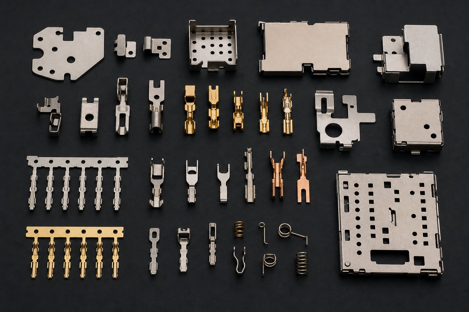
Electrical connectors and terminals are the flagship application. A single vehicle platform can consume 200 to 400 distinct stamped terminals, each produced in volumes of 5 to 50 million per year across a model lifecycle. These parts are typically 0.008 to 0.032 inch phosphor bronze or brass, formed at 1,000 to 1,500 SPM. The automotive stamping die for a multi-cavity connector terminal might run 20 to 30 stations and produce two or four parts per stroke to meet demand. Precision requirements are severe: contact spring force depends on bend angle consistency within plus or minus 0.5 degrees.
Consumer electronics shielding follows a similar profile. EMI shields, battery contacts, and micro-connector shells for smartphones and laptops are stamped from thin stainless steel or copper alloys at speeds exceeding 1,200 SPM. Part geometries are small, tolerances are tight, and annual volumes routinely reach tens of millions.
- Automotive electrical terminals: Phosphor bronze or brass, 0.008–0.032 in., ±0.001 in. tolerance, 5–50 million annual volume
- Sensor housings and brackets: Low-carbon steel or stainless, 0.020–0.060 in., ±0.002 in. tolerance, 1–10 million annual volume
- Electronics EMI shielding: Stainless steel or nickel silver, 0.005–0.015 in., ±0.001 in. tolerance, 10–100 million annual volume
- Battery contacts and springs: Beryllium copper or phosphor bronze, 0.006–0.020 in., ±0.0005 in. tolerance, 20–80 million annual volume
Medical Device and HVAC Component Stamping
Medical device progressive stamping targets a different value proposition: not just volume, but absolute repeatability in parts where dimensional variation can affect patient outcomes. Contact springs for diagnostic equipment, surgical instrument clips, and disposable device components all benefit from the consistency that high speed progressive dies deliver when properly maintained.
Medical progressive stamping typically uses 300-series stainless steel or specialty alloys in thicknesses from 0.005 to 0.030 inch. Speeds range from 600 to 1,200 SPM depending on material and complexity. The critical advantage is not raw throughput but the process stability that comes from a fully developed, sensor-monitored progressive die running in steady state. Every part is produced under identical conditions, stroke after stroke, which satisfies the documentation and traceability requirements that medical device manufacturers face.
HVAC progressive stamping serves the opposite end of the complexity spectrum: relatively simple bracket, clip, and mounting components produced in enormous quantities. A single residential HVAC unit contains dozens of stamped brackets, retaining clips, and formed sheet metal supports. Multiply that across millions of units annually and you get volume requirements that only high speed progressive stamping can serve economically. Materials are commonly galvanized steel or aluminum in the 0.020 to 0.080 inch range, running at 800 to 1,400 SPM.
- Medical contact springs: 300-series stainless or BeCu, 0.005–0.025 in., ±0.0005 in. tolerance, 2–20 million annual volume
- Surgical instrument clips: 17-7 PH stainless, 0.010–0.030 in., ±0.001 in. tolerance, 1–5 million annual volume
- HVAC mounting brackets: Galvanized steel or aluminum, 0.025–0.080 in., ±0.003 in. tolerance, 5–30 million annual volume
- HVAC retaining clips and fasteners: Spring steel or stainless, 0.015–0.040 in., ±0.002 in. tolerance, 10–50 million annual volume
The pattern across all these applications is consistent. High speed progressive die stamping delivers its greatest return where three conditions converge: annual volumes in the millions, thin-gauge materials suited to strip-fed production, and tolerances tight enough to demand the process stability that a well-engineered progressive die provides. If your part meets those criteria, the process is not just one option among many. It is likely the only option that hits your cost, quality, and delivery targets simultaneously.
For procurement teams ready to evaluate tooling partners across these application categories, YICHEN's progressive stamping die capabilities offer a starting point for sourcing dies engineered for high-volume production with the multi-station forming precision these industries demand.
FAQs About High Speed Progressive Die Stamping
1. What is the difference between high speed and standard progressive die stamping?
Standard progressive die stamping operates below 400 strokes per minute (SPM), suitable for larger parts and thicker materials. High speed progressive die stamping runs at 800 to 1,800+ SPM, targeting small-to-medium parts in thin-gauge materials (0.003 to 0.125 inch). This speed difference requires fundamentally different engineering across every system component, including specialized press frames with dynamic balancing, servo feed systems with programmable acceleration, carbide tooling to withstand thermal cycling, and in-die sensing for real-time quality monitoring at production rates exceeding one million parts per shift.
2. What materials work best for high speed progressive stamping?
Copper and brass alloys perform best at high speed due to low strain-rate sensitivity, supporting speeds of 1,000 to 1,800 SPM in thicknesses from 0.003 to 0.080 inch. Low-carbon steel handles 800 to 1,500 SPM reliably. Stainless steel is more demanding, limited to 600 to 1,200 SPM because it work-hardens rapidly and accelerates punch wear. Aluminum runs at 800 to 1,400 SPM but requires polished tooling and careful lubrication to prevent galling. Material choice directly affects achievable speed, die life, and sharpening intervals, so engineers must factor strain-rate behavior into process planning rather than relying solely on static material data sheets.
3. How do you maintain quality control at 1,000+ parts per minute?
Quality control at high speed relies on three integrated systems rather than manual inspection. First, in-die sensors including proximity sensors, micron sensors, and load monitors detect process anomalies on every stroke and stop the press before die damage occurs. Second, high-frame-rate vision systems with hardware-triggered strobes sample parts at intervals of every 5th to 20th piece for dimensional verification. Third, statistical process control (SPC) running on continuous tonnage and dimensional data detects trending before parts drift out of tolerance. Together, these systems enable condition-based maintenance scheduling that maximizes uptime while maintaining part quality.
4. When should I choose high speed progressive stamping over transfer or compound dies?
High speed progressive die stamping is optimal when annual volumes exceed 500,000 pieces, material thickness falls between 0.003 and 0.125 inch, and part geometry can be produced from a strip-fed approach without deep draws exceeding 1.5 times material thickness. Transfer dies are better for complex three-dimensional parts requiring deep drawing or multi-directional forming at moderate volumes. Compound dies suit simple flat profiles at lower volumes with less tooling investment. Fourslide machines handle complex multi-axis bending in thin materials more economically when part geometry demands it. The decision hinges on matching volume, geometry, and material to process strengths.
5. What should I look for when selecting a progressive die supplier for high speed applications?
Evaluate suppliers on six criteria: in-house die design capability with strip simulation and thermal analysis experience, material and metallurgical expertise for specifying carbide grades and coatings at high strain rates, ownership of high speed tryout presses that can validate die performance at actual production speeds, CMM-level metrology for verifying tight-tolerance stamping die components, production capacity to support ongoing wear-part supply without gaps, and after-sales technical support through the tool's production life. Suppliers like YICHEN focus specifically on progressive stamping dies for high-volume production requiring multi-station forming and tight repeatability. Always request reference checks with customers running similar high speed applications before committing.


