


What Die and Stamping Really Means in Manufacturing
Imagine holding a car door panel, a smartphone shield, or a tiny electrical connector. Each of these started as a flat sheet of metal. The process that transformed them into precise, three-dimensional parts? Die and stamping. It is the backbone of high-volume metalforming, yet many engineers and sourcing professionals encounter the terminology without a clear picture of how everything fits together.
This article walks you through the full lifecycle of die and stamping, from the tool concept and material selection all the way to production-floor troubleshooting. Whether you are evaluating suppliers, specifying parts, or simply building your technical vocabulary, you will find actionable detail in every section.
What Is a Die in Manufacturing
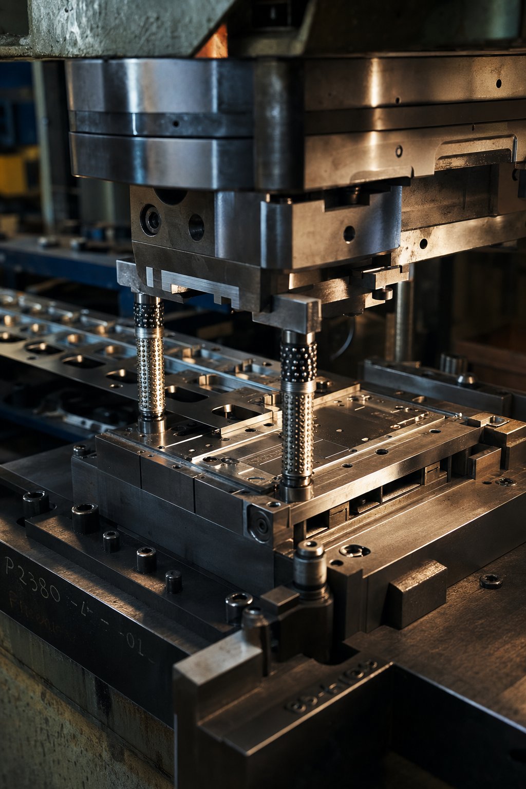
So, what is a die? In manufacturing, a die is a precision-machined tool engineered with a specific cavity, profile, or set of cutting edges that shapes raw material under force. Think of it as a highly specialized mold, but instead of pouring liquid into it, you are pressing solid sheet metal against it at high speed.
A stamping die typically consists of two complementary halves:
- Upper die (punch) - The moving component attached to the press ram. It descends into the material, applying force to cut or form the workpiece.
- Lower die (die block) - The stationary component mounted on the press bed. It contains the cavity or cutting edge that receives the punch and defines the final part geometry.
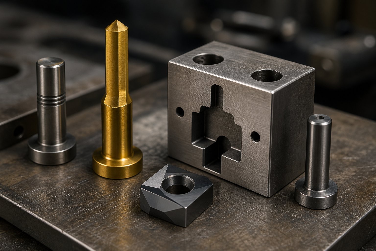
When people ask "what is dies in manufacturing" or "what are dies," they are referring to these custom-built tool sets, each one designed for a single part or family of parts. Dies range from palm-sized tools for microelectronics to massive assemblies weighing several tons for full automobile body panels. The cutting and forming sections are typically made from hardened tool steel or carbide inserts to withstand millions of press cycles.
What Is Stamping and How Does It Relate to Dies
If a die is the tool, stamping is the process that puts it to work. What is stamping, exactly? It is the high-speed metalforming operation where a press drives sheet metal into or through a die to produce finished or semi-finished components. The press supplies the force, the die supplies the geometry, and the sheet metal becomes the part.
Metal stamping is the manufacturing process that uses specialized dies mounted in a press to cut, bend, or form flat sheet metal into precisely shaped components at production speed.
The relationship between die design and stamping outcomes is symbiotic. A perfectly engineered die paired with the wrong press parameters will still produce scrap. Conversely, a well-tuned press cannot compensate for poor die geometry. Every variable in the die, from punch-to-die clearance to surface finish, directly influences part quality, cycle time, and tool longevity.
What is metal stamping used for in practice? Everything from blanking flat shapes out of a strip, to deep-drawing cylindrical cups, to coining fine surface details. A single progressive die can perform a dozen sequential operations in one press stroke, turning a continuous coil of metal into finished parts at rates exceeding 1,000 strokes per minute.
Why Die and Stamping Matters in Modern Manufacturing
Four qualities make this process nearly irreplaceable for medium-to-high volume production:
- Repeatability - Once a die is validated, every part it produces is dimensionally identical, whether it is the first piece or the millionth.
- Tight tolerances - Properly designed dies hold tolerances within thousandths of an inch, often eliminating secondary machining.
- Cost efficiency at scale - High upfront tooling cost is offset by extremely low per-part cost once production ramps up.
- Cross-industry versatility - Automotive body structures, aerospace brackets, electronic connectors, medical device housings, and consumer appliance panels all rely on stamped components.
The versatility extends to materials as well. Mild steel, stainless steel, aluminum, copper, and brass are all routinely stamped, each bringing unique formability characteristics that influence die design choices.
With definitions in place, the real depth begins at the tooling level, where selecting the right die type determines whether a project hits cost, speed, and quality targets or misses all three.
Types of Stamping Dies and When to Use Each
Picking the wrong die type for your project is like choosing a sledgehammer for finish carpentry. You might get results, but you will waste material, time, and budget along the way. The four major types of stamping dies each occupy a distinct performance envelope, and understanding their trade-offs is the fastest way to match tooling investment to production reality.
Progressive Dies and How They Work
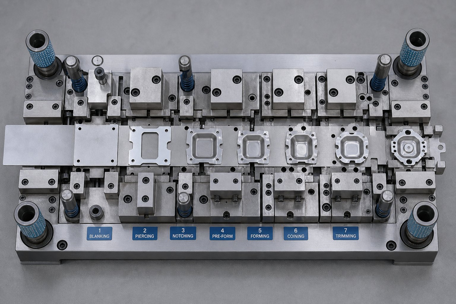
The progressive die stamping process revolves around a single, elegant concept: a continuous metal strip feeds through a series of stations inside one die, with each station performing a different operation, cutting, bending, forming, or piercing, in sequence. The strip acts as its own conveyor, carrying the partially formed part from one station to the next with each press stroke. At the final station, the finished component is separated from the carrier strip.
Why does this matter? Speed. A well-designed progressive die can produce complex parts at rates exceeding several hundred strokes per minute while maintaining tight tolerances across all stations. That makes progressive dies the workhorse behind high-volume automotive stamping dies, electronic connectors, and small precision brackets.
Pros
- Extremely high throughput with minimal manual handling
- Tight dimensional consistency from station to station
- Minimal material waste through optimized strip layouts
- Lower labor costs once production is running
Cons
- Higher initial tooling investment due to multi-station complexity
- Part geometry constraints: deep draws and very large parts are difficult to accommodate while the workpiece remains attached to the strip
- Design changes after build are costly and time-consuming
Transfer Dies for Larger and Complex Parts
What happens when your part is too large or too deeply drawn to stay connected to a strip? That is where transfer die stamping takes over. In this approach, a blank is cut free from the stock material at the first station and then physically moved between subsequent stations by mechanical fingers or automated grippers.
Because the workpiece is independent of a carrier strip, transfer stamping accommodates deeper draws, larger geometries, and operations like threading or knurling that would be impossible in a progressive setup. Aerospace structural components, large appliance panels, and heavy automotive body sections frequently rely on this method. The trade-off is slower cycle speed and higher setup complexity compared to progressive tooling, but the design freedom is substantially greater.
An often-overlooked benefit: transfer dies eliminate the carrier web connecting parts in a progressive strip, which can reduce raw material consumption on each piece and lower overall part cost for larger components.
Compound and Combination Dies
Compound die stamping performs multiple cutting operations in a single press stroke. Imagine blanking a washer: the outer diameter and inner hole are punched simultaneously in one downward motion. The result is a flat, highly accurate part produced quickly and cost-effectively. Compound dies excel at simple geometries where flatness and edge quality are critical, such as gaskets, shims, and electrical laminations.
Combination dies go one step further. They execute both cutting and forming operations in a single stroke, producing a part that is not only blanked to shape but also bent or drawn in the same hit. When your part is moderately complex but volume does not justify the investment of a full progressive tool, a combination die fills the gap neatly.
The key distinction: compound dies only cut; combination dies cut and form. Choosing between them depends on whether your finished part requires any non-planar geometry.
Consolidated Comparison of Die Types
When evaluating sheet metal stamping dies for a new project, the table below maps each type against the decision factors that matter most to tooling engineers and sourcing managers:
| Die Type | Best-For Part Complexity | Ideal Production Volume | Typical Tolerance Range | Relative Tooling Cost | Cycle Speed |
|---|---|---|---|---|---|
| Progressive | Small to medium parts with moderate complexity (bends, holes, forms) | High volume (100K+ annually) | ±0.025 mm to ±0.1 mm | High | Very fast (200-1,500+ SPM) |
| Transfer | Large or deeply drawn parts with intricate features | Medium to high volume (10K-500K+) | ±0.05 mm to ±0.15 mm | High | Moderate (15-80 SPM) |
| Compound | Flat, simple parts requiring precise cut edges | Low to high volume (flexible) | ±0.025 mm to ±0.075 mm | Low to medium | Fast (100-400 SPM) |
| Combination | Moderately complex parts needing cut and form in one hit | Low to medium volume (1K-50K) | ±0.05 mm to ±0.1 mm | Medium | Moderate (60-200 SPM) |
Notice that no single die type dominates across every column. Progressive dies win on speed but demand high upfront investment. Transfer dies deliver geometric freedom at the expense of cycle time. Compound dies keep costs low for simple parts, while combination dies offer a middle path for moderate complexity at moderate volume.
The right choice ultimately hinges on three questions: how complex is the part, how many do you need per year, and what tolerances does the application demand? Answering those up front steers you toward the stamping dies that balance cost and capability without over- or under-investing in tooling.
Of course, selecting the die type is only half the equation. Each type still relies on a set of core stamping operations, blanking, piercing, bending, drawing, and more, that define what actually happens to the metal at each station.
Core Stamping Operations Explained With Applications
Every stamped part, whether it is a flat washer or a deep-drawn automotive cup, owes its shape to a specific sequence of operations performed inside the die. These operations are the vocabulary of the stamping process, and understanding each one helps you predict how a design will behave under the press, where defects might appear, and what tolerances are realistically achievable.
Imagine you are flipping through a finished part's operation sheet. You will see terms like blanking, piercing, bending, drawing, and coining listed in order. Each entry represents a distinct interaction between the punch and die. Here is what actually happens at each step, and why it matters for your design.
Blanking and Piercing Operations
Stamping blanking and piercing are both shearing operations, meaning they separate material by forcing a punch through the sheet and into a die opening. The difference lies in which piece you keep.
In blanking, the piece punched out of the strip is the desired workpiece. Think of cutting cookie shapes from dough: the cookie is the blank, and the remaining dough is scrap. In piercing (sometimes called punching stamping), the strip itself remains the workpiece, and the small slugs removed to create holes or slots are discarded.
The critical design parameter for both operations is punch-to-die clearance, which is the gap between the cutting edges of the punch and die. This clearance is expressed as a percentage of material thickness and varies by material type. For mild steel, a clearance of roughly 5-10% per side is typical. Too little clearance causes excessive tool wear and double-shear marks; too much creates heavy burrs and poor edge quality. Getting this balance right determines whether your sheet metal stamping process produces clean edges or generates scrap that jams the die.
Bending, Forming, and Drawing
Once the flat blank or strip has been cut to shape, the next family of operations transforms it into a three-dimensional part.
- Bending - Simple angular deformation along a straight axis. Common applications include brackets, channels, and flanges. The primary design constraint is springback: the material's elastic recovery causes it to partially unbend after the punch retracts. Engineers compensate by overbending the part a few degrees beyond the target angle so it relaxes back to the correct position.
- Forming - Complex contour shaping that bends the material along curved or compound axes. Used for automotive body panels, appliance housings, and structural stiffeners. The key constraint is controlling material flow to prevent wrinkling in compressed areas and thinning in stretched areas.
- Drawing - Pulling sheet metal into a die cavity to create depth, producing hollow shapes such as cups, cans, and enclosures. The design challenge here is managing the blank holder force: too little allows wrinkling at the flange, while too much restricts material flow and causes tearing at the punch radius.
Springback deserves special emphasis because it affects nearly every operation that deforms metal without cutting it. Advanced high-strength steels and aluminum alloys exhibit significantly more springback than mild steel, sometimes requiring iterative simulation and compensation strategies during die design to achieve dimensional compliance. The systematic approach of measuring, mitigating, controlling, and compensating for springback has become standard practice for these materials.
Coining, Embossing, and Secondary Operations
Beyond cutting and forming, several finishing operations refine a stamped part's features or add functional details. What is die cutting in relation to these secondary steps? While die cutting broadly refers to any shearing operation performed by a die (blanking and piercing included), the term also encompasses precision trimming and notching operations that clean up formed parts before they leave the press.
- Coining - A high-pressure compression operation that squeezes metal between punch and die faces, causing it to flow and fill every detail of the tool cavity. Common applications include electrical contacts requiring precise thickness, currency, and bearing surfaces. The primary constraint is the extremely high tonnage required, often three to five times greater than forming operations on the same material.
- Embossing - Raises or recesses patterns, text, or surface textures into the sheet without cutting through it. Used for branding, stiffening ribs, and functional textures on heat shields. The constraint is maintaining consistent material thickness so the embossed feature does not create a weak point or distort the surrounding geometry.
- Die cut trim and secondary operations - After primary forming, parts may need trimmed flanges, tapped holes, or spot-welded inserts. Progressive dies can integrate these steps at downstream stations, while standalone parts may move to dedicated fixtures. The design consideration is ensuring that secondary operations do not distort the part geometry achieved during earlier forming stages.
Each of these operations can be combined within a single die or distributed across multiple stations depending on part complexity and production volume. A progressive die, for instance, might blank and pierce at the first two stations, form at the third, draw at the fourth, and coin a critical surface at the fifth, all in a single press stroke completing the full stamping process in under a second.
Knowing what each operation demands from the tooling leads directly to the next critical question: what materials and design parameters must engineers specify to ensure the die performs reliably across hundreds of thousands, or even millions, of cycles?
Die Materials and Design Considerations for Engineers
A die can be perfectly shaped and still fail prematurely if it is built from the wrong material. The geometry gets all the attention during design reviews, but the steel behind that geometry is what determines whether your die tool lasts fifty thousand hits or five million. Stamping die design is fundamentally a materials engineering challenge disguised as a geometry problem.
Die Material Selection and Surface Treatments
Every metal die starts as a block of tool steel, and the grade you choose sets a ceiling on performance. The decision comes down to balancing three competing properties: hardness, toughness, and wear resistance. Push too hard on one, and you sacrifice another.
Here are the most common material families used in steel stamping dies:
- D2 tool steel - A high-carbon, high-chromium steel with exceptional wear resistance. Its dense carbide structure makes it ideal for blanking and piercing dies running abrasive materials over long production campaigns. The trade-off? D2 is more brittle than other tool steels and can chip under high-shock loads.
- A2 tool steel - An air-hardening, medium-alloy steel offering a balanced profile of wear resistance and toughness. A2 resists chipping better than D2, making it versatile for forming dies and complex punch geometries where impact forces are significant.
- M2 high-speed steel (HSS) - Retains hardness at elevated temperatures generated during high-speed operations. This property, known as red hardness, prevents cutting edges from softening during rapid cycling. M2 bridges the gap between conventional tool steels and carbide.
- Tungsten carbide inserts - When wear resistance must be extreme, carbide is unmatched. It is significantly harder than any steel but also more brittle, so it is typically used as inserts in high-wear zones rather than as a full die block material. Carbide justifies its cost on runs in the hundreds of thousands or millions of parts.
The base material is only part of the equation. Surface treatments extend die life dramatically without changing bulk properties. Titanium Nitride (TiN) coatings add a hard, low-friction layer that reduces galling when forming stainless steel. Titanium Carbonitride (TiCN) offers even higher hardness for more abrasive workpiece materials. Nitriding diffuses nitrogen into the die surface, creating a wear-resistant case while preserving core toughness. Matching the right coating to your workpiece material and production volume is one of the fastest ways to lower per-part cost on metal press dies without a full die rebuild.
A practical rule of thumb: short runs and prototyping can often justify economical steels like O1; medium-volume production suits A2; and high-volume or abrasive applications call for D2 or carbide inserts with advanced coatings.
Critical Design Parameters for Die Engineers
Material selection gives the die its durability. Stamping design parameters give it precision. Several calculations must be locked down before any CNC program is written:
- Punch-to-die clearance - The gap between cutting edges, expressed as a percentage of material thickness per side. Standard practice recommends roughly 10% per side as a starting point, though harder materials require increased clearance and fine-blanking applications demand much less. Too tight increases tool wear; too loose produces heavy burrs.
- Strip layout optimization - Arranging part blanks on the coil strip to maximize material utilization. Even a 2-3% improvement in layout efficiency compounds into significant savings over a million-part run.
- Pilot pin positioning - Pilots register the strip at each station to maintain consistent alignment. Misplaced or worn pilots cause cumulative positional error that shows up as misaligned holes or inconsistent trim lines downstream.
- Station sequencing - In progressive dies, the order of operations matters. Piercing typically precedes forming because holes punched into a flat strip are more dimensionally stable than holes pierced after bending. Sequencing decisions directly impact final part tolerance.
Each of these parameters interacts with the others. Changing material thickness, for example, ripples through clearance values, press tonnage calculations, and strip width requirements. A disciplined metal stamping die design process documents these interdependencies early so that downstream changes do not cascade into costly die rework.
Workpiece Material Properties and Their Impact on Die Design
You cannot design a sheet metal die in isolation from the material it will stamp. Tensile strength, ductility, and thickness of the workpiece dictate clearance values, forming force, and springback compensation strategy. A die engineered for mild steel will not perform the same way on stainless steel or aluminum, even if the part geometry is identical.
Consider three key interactions:
- Tensile strength and forming force - Higher-strength materials demand more press tonnage and place greater stress on die components. This means harder die materials and more robust die construction.
- Ductility and formability - Materials with high elongation (like copper or mild steel) flow readily into complex shapes. Low-ductility materials restrict achievable draw depths and tight radii.
- Springback tendency - Materials with higher yield strength and elastic modulus spring back more aggressively after forming. High-strength steels and aluminum require overbend compensation built directly into the die geometry.
The table below maps common workpiece materials against the factors that most influence die tool selection and design decisions:
| Workpiece Material | Formability Rating | Springback Tendency | Die Wear Impact | Typical Clearance (% per side) |
|---|---|---|---|---|
| Mild steel (low carbon) | High | Low to moderate | Moderate | 5-8% |
| Stainless steel (304/316) | Moderate | High | High (abrasive, work-hardens) | 8-12% |
| Aluminum (5052/6061) | Moderate to high | High | Low (but prone to galling) | 8-10% |
| Copper (C110) | Very high | Low | Low | 5-7% |
| Brass (C260) | High | Low to moderate | Low to moderate | 5-8% |
Notice the pattern: materials that are harder and stronger demand wider clearances and more wear-resistant die steels. Stainless steel, for instance, work-hardens rapidly during forming, which accelerates die wear and often justifies TiN-coated or carbide-inserted tooling. Aluminum does not wear the die as aggressively but has a tendency to gall (cold-weld to the die surface), making low-friction coatings essential.
These material-driven decisions ripple all the way from initial die concept through maintenance scheduling. A die designed with careful attention to workpiece properties will not only produce better parts on day one but will also maintain dimensional accuracy far deeper into its service life, which leads directly to the question of how that die gets built in the first place.
The Die Build Process From Design Through Tryout
A die does not spring into existence overnight. Between the initial part drawing and the first production-quality stamped component lies a structured, multi-phase workflow that transforms raw tool steel into a precision instrument capable of repeating the same operation millions of times. The die making process is where engineering theory meets physical reality, and every shortcut taken here shows up later as scrap, rework, or premature tool failure.
Whether you are a tooling engineer managing a build internally or a sourcing manager evaluating a supplier's capabilities, understanding what happens at each stage helps you ask better questions, set realistic timelines, and spot red flags early.
Feasibility Analysis and CAE Simulation
Every serious die manufacturing project starts with a question: can this part actually be stamped as drawn? Feasibility analysis is the first gate, and it examines part geometry, material selection, thickness, tolerances, and anticipated production volume to determine whether the design is manufacturable without excessive risk.
Once feasibility is confirmed, Computer-Aided Engineering (CAE) simulation takes over. Using finite element analysis (FEA), engineers digitally model how the sheet metal will behave inside the die: where the material thins, where it wrinkles, where springback will pull dimensions out of spec. Simulation software predicts these defects before any steel is cut, allowing engineers to adjust draw radii, blank holder pressure, and die geometry in a virtual environment rather than through expensive physical trial-and-error.
The cost savings here are substantial. According to insights from Keysight's forming simulation research, virtual die tryouts can eliminate the majority of formability issues before prototyping begins, cutting weeks from development timelines and avoiding costly tooling modifications after hardening. For difficult materials like advanced high-strength steels or aluminum alloys, simulation is not optional; it is the only practical way to predict and compensate for springback magnitudes that would otherwise require multiple physical correction cycles.
CNC Machining, EDM, and Assembly
With simulation data validated, die machining begins. This phase turns hardened steel blocks into the precision surfaces that will shape every part the die produces. The sequence typically follows this path:
- CNC milling - Rough and semi-finish machining of die blocks, punch holders, and stripper plates. Five-axis CNC centers handle complex contours in a single setup, reducing cumulative positional errors.
- Heat treatment - Die components undergo vacuum furnace hardening to achieve target hardness (typically HRC 58-62), followed by tempering to balance hardness with toughness.
- Wire EDM - Intricate punch profiles and tight-tolerance openings are cut using a fine brass wire electrode. Wire EDM achieves tolerances as tight as ±0.005 mm on hardened steel, making it essential for complex blanking and piercing geometries.
- Surface grinding - Ensures flatness of mating surfaces so upper and lower die halves align precisely across the entire shut height.
- Assembly - Guide pins, bushings, springs, pilots, and stripper components are fitted together. A master die maker performs a dry run, manually cycling the assembled tool die to check for interference before it ever sees a press.
The tool and die making craft lives in these details. Each component must fit within microns of its design intent, because any sloppiness compounds with every press stroke. This is why experienced die makers rely on closed-loop metrology, inspecting critical dimensions at each stage rather than waiting for final assembly to reveal errors.
Trial Runs, Adjustment, and Final Inspection
The tryout phase is where the die proves itself or exposes its weaknesses. The assembled die is mounted in a tryout press, and sample parts are stamped using production-representative material. These first-article parts are then measured against GD&T specifications using coordinate measuring machines (CMMs) and optical comparators.
Rarely does a die produce perfect parts on its first hit. The iterative adjustment process, sometimes called spotting or blue-matching, fine-tunes forming surfaces, corrects springback compensation, and optimizes punch-to-die clearances based on actual part measurements. Each cycle produces data that drives the next adjustment until all critical dimensions fall within tolerance.
Final inspection documents everything: dimensional reports, material certifications, hardness test results, and surface finish measurements. Only after this comprehensive validation is the die released for production.
Full-service die builders structure this entire workflow under one roof. YICHEN, for example, takes custom stamping die projects through a complete sequence, from feasibility review and CAE simulation through CNC machining, trial runs, and final inspection, giving manufacturers and sourcing managers a single point of accountability from concept to production-ready tooling. For readers evaluating tool die making partners, this end-to-end model eliminates the coordination overhead of splitting stages across multiple vendors.
The die maker tools and technologies described here represent established best practices in tool and die manufacturing. But the industry is not standing still. Advances in servo press technology, digital simulation, and connected factory systems are reshaping what is possible on the production floor, pushing cycle speeds higher and defect rates lower than ever before.
Modern Stamping Technologies Transforming the Industry
The die build process may follow a well-established sequence, but the equipment and software driving each stage have changed dramatically. Stamping technology is evolving in ways that affect everything from how a press delivers force to how an engineer predicts defects months before a die reaches the shop floor. If you are specifying tooling or evaluating suppliers, understanding these advances helps you ask sharper questions and recognize which capabilities actually translate into better parts.
Servo Press Technology and Its Advantages
How does a stamping press work in a traditional setup? A flywheel stores kinetic energy, a clutch engages, and the ram descends through a fixed motion profile dictated by the crank geometry. Speed is constant. Dwell time is negligible. You get what the mechanical linkage gives you, and difficult-to-form materials either cooperate or tear.
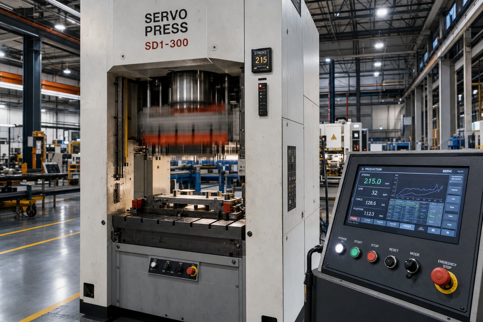
A servo-driven die stamping press rewrites those constraints. Instead of a flywheel and clutch, a direct-drive servo motor controls the slide position, velocity, and dwell time through a fully programmable stroke profile. Engineers can slow the ram at the moment of material contact, hold it at bottom dead center to let the metal flow, and accelerate through non-working portions of the stroke, all within a single cycle.
The practical benefits compound quickly:
- Variable speed within a stroke - Allows slower forming speeds for deep draws on aluminum or high-strength steel, reducing tearing and thinning without sacrificing overall cycle time.
- Programmable dwell - Holding the punch at full depth lets material relax, improving dimensional accuracy and reducing springback on difficult geometries.
- Energy efficiency - The servo motor draws power primarily during the working portion of the cycle and employs regenerative braking during deceleration, resulting in substantially lower total energy consumption compared to continuously running mechanical presses.
- Reduced noise and vibration - Soft-touch contact profiles eliminate the impact shock that characterizes conventional high-speed stamping, extending die life and improving shop-floor conditions.
For stamping tooling designed to handle advanced materials, servo presses unlock forming windows that simply do not exist on fixed-stroke machines. The die stamping machine and the die itself become a coordinated system rather than two independent pieces of hardware.
Simulation Software in Die Design
Physical trial-and-error on a tryout press is expensive. Every failed iteration burns press time, engineering labor, scrap blanks, and schedule margin. FEA-based forming simulation software addresses this by digitally replicating the entire stamping manufacturing process before a single block of steel is machined.
Modern simulation tools predict where material will thin beyond safe limits, where wrinkling will occur due to excess compression, where springback will push dimensions out of tolerance, and whether the chosen draw bead geometry and blank holder force are optimized. Engineers test dozens of configurations in hours rather than weeks, adjusting blank shape, draw depth, and bead layout in a virtual environment.
The return on investment is compelling. Industry data from automotive die programs shows that simulation-guided tooling typically requires only one to two physical tryout iterations, compared to three to six iterations for dies developed without forming simulation. Simulation fees generally represent 3-8% of total tooling cost, yet the savings from eliminated rework and compressed timelines consistently deliver five to ten times that investment in return.
For stamping press parts that involve high-strength steels above 590 MPa or aluminum panels, springback compensation alone can add three to five physical correction cycles without simulation. Building that compensation directly into the die geometry from simulation data transforms a multi-week debugging exercise into a predictable, controlled step.
Industry 4.0 Integration in Stamping Operations
The stamping manufacturing floor is getting connected. Industry 4.0 principles, the convergence of sensors, IoT devices, and cloud analytics, are turning presses from isolated machines into data-generating nodes on a networked production line. Here are the key technologies reshaping daily operations:
- In-die force sensors - Embedded load cells monitor forming and cutting forces in real time, detecting tool wear or material variation before it produces out-of-spec parts. Sudden force spikes trigger automatic press stops, protecting both the die and the product.
- Predictive maintenance via vibration and temperature monitoring - Sensors on press bearings, guide columns, and die components track vibration signatures and thermal drift. Machine learning algorithms flag early warning signs of wear or impending failure, allowing maintenance teams to intervene before a breakdown halts production.
- Quick-die-change (QDC) systems - Hydraulic clamping, automatic bolster transfer, and pre-staged tooling reduce die changeover from hours to minutes. On high-mix production lines, QDC directly increases available press uptime.
- Statistical process control (SPC) at the press - Connected stamping lines feed dimensional and force data into centralized SPC dashboards. Trends become visible in real time, enabling process corrections before scrap accumulates rather than after a batch is rejected at final inspection.
- Digital twins - Virtual replicas of the physical press and die simulate operations, identify bottlenecks, and validate parameter changes before they reach the production floor, reducing risk during process optimization.
Together, these technologies shift the stamping manufacturing process from reactive to predictive. Instead of waiting for a defect to appear on a part, connected systems flag the conditions that cause defects and intervene upstream. The result is higher uptime, lower scrap rates, and maintenance schedules driven by actual equipment condition rather than arbitrary calendar intervals.
These advances push productivity higher, but they do not eliminate the fundamental reality of die wear. Even the most sophisticated servo press and sensor-equipped production line still depends on disciplined maintenance and rapid defect diagnosis to keep parts within tolerance over the long haul.
Die Maintenance and Troubleshooting Stamping Defects
Sensor networks and servo presses can flag anomalies, but someone still has to open the die, diagnose the root cause, and fix it. Stamping die maintenance is where production longevity is either protected or quietly eroded, one missed inspection at a time. A disciplined maintenance program does not just prevent breakdowns. It holds part quality steady across hundreds of thousands of hits, keeps per-part costs predictable, and avoids the cascading failures that turn a minor burr into a full press stoppage.
Preventive Maintenance Schedules and Best Practices
A good maintenance program blends time-based checks with stroke-count triggers. Calendar intervals ensure that routine care is never skipped during heavy production weeks, while hit-based thresholds account for the reality that dies do not wear at the same rate regardless of how many days pass between runs.
Here is what a practical schedule looks like for a typical stamping die set running moderate-to-high volume production:
- Per shift - Visual check for burrs on parts, slug buildup in the die cavity, abnormal noise, and lubricant delivery confirmation. Flag any edge-related quality change immediately.
- Daily - Inspect pilots, springs, guides, and scrap flow paths. Clean contact surfaces and verify critical hardware remains secure.
- Weekly - Measure wear items against documented service criteria. Torque-check fasteners with a loosening history and update hits-per-service records.
- Monthly - Deep clean sections prone to contamination buildup. Review guides, shims, and timing stability. Plan sharpening based on wear trends rather than guesswork.
- Stroke-count triggers - Schedule sharpening reviews and component replacement based on actual hits-per-service data for each process die, not arbitrary calendar intervals.
Frequency should tighten when material becomes more abrasive (stainless steel wears tooling faster than copper), when part tolerances are demanding, or when die complexity creates more places for alignment loss. Industry guidance from preventive maintenance specialists recommends building schedules around baseline measurements like downtime frequency, first-time capability, and throughput variability rather than adopting a one-size-fits-all template.
Key stamping die components that demand attention at every PM stop include cutting edges and punches, stripper plates and springs, guide pins and bushings, pilot pins, and scrap evacuation paths. A worn spring that no longer strips the part cleanly or a guide bushing developing play will produce dimensional drift long before it causes a catastrophic failure.
Troubleshooting Common Stamping Defects
When parts start coming off the press with visible quality issues, resist the urge to immediately regrind the die. Many stamping forming issues trace back to setup drift, lubrication failures, or loose hardware rather than actual tool wear. A systematic approach saves time and avoids unnecessary die repair.
Start with the simplest, most reversible causes: trapped slugs, blocked scrap paths, poor lubricant delivery, feed pitch issues, and loose mounting surfaces. Only after ruling these out should you move deeper into cutting edges, worn guides, or damaged inserts.
The table below maps the most common defects to their root causes and corrective actions:
| Defect Type | Primary Causes | Corrective Actions | Prevention Strategies |
|---|---|---|---|
| Wrinkling | Insufficient blank holder force; improper draw bead design; excessive material flow into cavity | Increase blank holder pressure; redesign draw beads; verify nitrogen spring or cushion pressure | Validate blank holder force during tryout; monitor cushion pressure each shift; simulate material flow before production |
| Tearing | Excessive thinning from tight radii; insufficient lubrication; material tensile strength exceeding design assumptions | Increase draw radii; improve lubricant delivery; verify incoming material specs against die design | Specify minimum radii during die design; establish lubrication checks per shift; implement incoming material inspection |
| Burr formation | Worn cutting edges; excessive punch-to-die clearance; chipped punch or die button | Sharpen or regrind cutting edges; restore proper clearance; replace damaged inserts | Track sharpening intervals against hit count; inspect edges at scheduled PM stops; use wear-resistant coatings |
| Springback | Inadequate overbend compensation; material yield strength variation; worn forming surfaces | Increase overbend angle in die geometry; adjust tonnage; verify material lot consistency | Build springback compensation from CAE simulation; monitor material certifications lot-to-lot; inspect forming surfaces monthly |
| Dimensional drift | Worn pilot pins; thermal expansion during long runs; loose die mounting; guide bushing wear | Replace worn pilots; allow thermal stabilization before measuring; retorque mounting hardware; service guides | Track dimensional trends against hit count; implement warm-up protocol for long runs; check pilots and guides at each PM interval |
Notice a pattern: most corrective actions involve restoring the die to its designed condition rather than inventing new solutions. If the same defect recurs after a verified correction, the root cause likely sits in the die design itself or in a stamp die set component that has reached end of life, not in the last adjustment made.
Extending Die Life Through Proactive Care
Three factors dominate die longevity more than any others: lubrication, material quality control, and press alignment.
- Lubrication - Correct lubricant type, application volume, and coverage area reduce friction-driven wear on forming surfaces and prevent galling. A lubricant that worked for mild steel may fail entirely on stainless steel. Match the lubricant to the workpiece material and verify delivery every shift.
- Material quality control - Variations in incoming coil thickness, hardness, or surface finish force the die to work outside its design window. Even small deviations in tensile strength accelerate wear on cutting edges and forming radii. Material inconsistencies in composition or surface quality are among the most frequent root causes of premature defects in precision stamping.
- Press alignment - A press with ram parallelism issues distributes force unevenly across die sets, causing one-sided wear that no amount of maintenance can overcome. Regular press calibration protects every die that runs in it.
How long should a die last? Typical lifespan expectations vary enormously. A hardened D2 blanking die stamping mild steel with proper maintenance may run several million hits. The same geometry in a forming application on stainless steel might require insert replacement at 200,000-300,000 strokes. Die material, workpiece material, production speed, and maintenance discipline all shift that number. The dies that last longest are the ones built with realistic service expectations and maintained against actual wear data rather than optimistic assumptions.
Maintenance keeps a die running. But at some point, the question shifts from how to maintain the tool to whether the investment in that tool was justified in the first place, and how cost and production volume should guide the next tooling decision.
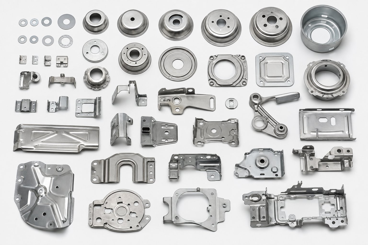
Cost Factors and Volume Decisions for Die Investment
A die that runs beautifully but never reaches its break-even volume is not a success story. It is an expensive shelf ornament. Tooling decisions are engineering decisions, yes, but they are also financial ones. Understanding what drives cost and how production volume reshapes the economics helps you invest in the right level of tooling without overspending on capability you will never use or underspending on a tool that cannot survive the run.
What Drives Stamping Die Cost
Two quotes for seemingly identical stamped metal parts can differ by an order of magnitude. That gap usually traces back to tooling, not the metal itself. According to Jennison Corporation's cost breakdown, tooling complexity is the single largest cost driver in any stamping project, and these are the factors that compound it:
- Number of stations - Each operation (piercing, bending, forming, trimming) requires its own station in a progressive die. A simple bracket needing three stations costs a fraction of an automotive housing requiring twenty.
- Forming difficulty - Deep draws, tight radii, and compound curves demand more sophisticated die geometry, tighter machining tolerances, and often servo press compatibility. Complex forming translates directly into more engineering hours and more CNC time.
- Die material grade - A prototype tool built from pre-hardened steel costs far less than a production die using D2 inserts with TiN coatings rated for millions of cycles. The expected run life dictates material investment.
- Tolerance requirements - Precision die stamping with tolerances below ±0.05 mm demands wire EDM profiles, tighter clearances, and more iterative tryout cycles. Each decimal place of precision adds cost nonlinearly.
- Part size - Larger parts need larger die blocks, bigger presses, and more raw steel. A stamped steel structural bracket for an automotive frame requires substantially more tooling mass than a fingertip-sized connector.
- Integrated secondary operations - In-die tapping, PEM fastener insertion, or resistance welding built into the progressive die increases upfront tooling complexity. However, these additions often reduce total per-part cost by eliminating downstream handling and separate fixturing.
The takeaway: tooling cost is not arbitrary. It reflects quantifiable decisions about complexity, durability, and precision. Understanding which factors your project actually requires, versus which are nice-to-have, is the fastest path to a right-sized investment.
Production Volume Thresholds and Die Type Selection
Volume changes everything in stamping economics. A die that costs $80,000 adds $16 per part across a 5,000-piece run but only $0.16 per part across 500,000 pieces. That asymptotic cost curve, as automotive stamping cost research confirms, is what makes volume the great equalizer in industrial metal stamping.
Here is how annual volume expectations map to appropriate die investment levels:
| Annual Volume | Recommended Die Approach | Rationale |
|---|---|---|
| Under 5,000 parts | Simple compound dies or hand-transfer tooling; consider laser cutting as an alternative | Tooling amortization per part remains too high for complex dies to break even |
| 5,000 - 50,000 parts | Combination dies or short progressive dies with fewer stations | Moderate tooling investment offsets per-part labor and cycle time costs |
| 50,000 - 200,000 parts | Full progressive dies with hardened inserts | High-speed cycling and tight tolerances justify the tooling spend; per-part cost drops sharply |
| 200,000+ parts | Complex progressive or transfer dies with carbide inserts, automated material handling, and in-die secondary operations | Maximum automation and durability minimize per-part cost and labor; die life measured in millions of strokes |
These thresholds shift depending on part complexity and current manufacturing method. A metal stamped part with simple geometry might justify stamping at lower volumes, while a deeply drawn component may need higher quantities to offset tooling. The critical question is not just "how many parts do I need?" but "what is my current per-part cost, and at what volume does stamping beat it?"
Calculating ROI on Tooling Investment
Tooling ROI is not a mystery. It is arithmetic, but it requires looking beyond piece price to total cost of ownership. The core formula is straightforward:
Total Cost = Fixed Costs (Design + Tooling + Setup) + (Variable Cost Per Unit x Volume)
Variable cost per unit includes raw material, press time (based on machine hourly rate and cycle speed), labor, and overhead. Industry estimation models typically show raw material accounting for 60-70% of the variable piece price on metal stamping components, with press time and labor splitting the remainder.
Where ROI calculations often fall short is in ignoring downstream savings. A die engineered with tighter tolerances may cost more upfront but can eliminate secondary machining, deburring, or inspection operations that otherwise add cost to every single part. Similarly, metal parts stamping with integrated in-die operations (tapping, hardware insertion) reduces handling steps and the quality risk that comes with moving parts between workstations.
When evaluating whether a tooling investment makes sense for your project, work through this decision checklist:
- Define the total expected lifetime volume, not just the first order. A five-year outlook changes the math significantly compared to a single annual purchase.
- Calculate your current per-part cost using existing methods (machining, laser cutting, manual fabrication) and include all secondary operations, inspection, and handling.
- Obtain tooling quotes that specify die life expectancy in strokes, so you can amortize accurately across lifetime volume.
- Compare per-part cost at your expected volume against your current method. Include material scrap rates, since efficient strip layout in progressive dies often reduces waste compared to individual blank cutting.
- Factor in downstream cost elimination: will tighter stamping tolerances remove a machining step? Will in-die operations eliminate a separate assembly station?
- Assess risk: what happens if volume falls short of projections? Could the die serve a secondary part or be modified economically?
- Evaluate total landed cost, including logistics, packaging, quality documentation, and supplier communication overhead, not just piece price.
Stamping parts become dramatically cheaper as volume scales, but only if the tooling investment is calibrated to realistic demand. Overinvesting in a complex progressive die for a 3,000-piece annual run is as wasteful as underinvesting in a simple compound tool that wears out halfway through a 500,000-piece contract.
The financial framework clarifies which tooling path to take. But choosing the right level of investment is only part of the sourcing equation. Equally important is selecting a die partner with the technical depth and quality systems to deliver on that investment, a decision that carries its own set of evaluation criteria.
Selecting the Right Stamping Die Partner for Your Project
Knowing what tooling you need and how much to invest only matters if the partner building that tool can deliver on the specifications. A stamping die is only as good as the team behind it, and the wrong supplier can turn a well-planned project into months of corrections, missed tolerances, and production delays. So what separates a capable die maker from one that just looks good on paper?
Quality Control Methods in Stamping Production
Quality in sheet metal stamping is not something you bolt on at the end. It is built into the die design, monitored throughout production, and verified at every transition point. A supplier with mature quality systems catches problems upstream, before they compound into costly scrap or line stoppages.
Look for these inspection touchpoints when evaluating a potential partner:
- First-article inspection (FAI) - The initial parts off a new or reworked die are measured against the full GD&T drawing to validate that the tool produces conforming geometry before production begins.
- In-process SPC - Statistical process control tracks critical dimensions at defined intervals during the run, detecting drift before parts leave tolerance. This is where real-time corrections happen.
- Final inspection - A comprehensive check of dimensional, surface, and functional requirements on completed lots before shipment. Documentation includes measurement reports, material certifications, and lot traceability.
The measurement tools backing these checkpoints matter just as much. Coordinate measuring machines (CMMs) handle complex 3D geometries. Optical comparators verify profiles and radii quickly. Go/no-go gauges provide rapid pass/fail screening on the production floor without slowing cycle time. A supplier that relies solely on handheld calipers for precision work is a red flag.
Capable die makers build quality into the tool itself through features like controlled clearances, self-aligning pilots, and wear-compensating inserts, so the die produces good parts inherently rather than relying on downstream sorting to catch defects.
What to Look for in a Stamping Die Supplier
What is a tool and die maker, really? Beyond the traditional definition of a craftsperson who builds precision tooling, the term today encompasses engineering capability, simulation expertise, and production-scale quality systems. The best die makers combine hands-on toolmaking skill with digital design sophistication.
When you are moving from research to RFQ, evaluate potential partners against these criteria:
- End-to-end capability demonstrated in practice - YICHEN, for example, covers the full workflow from feasibility analysis and CAE simulation through CNC machining, trial runs, and final inspection under one roof. This single-source model shows what a full-service diemaker looks like in practice: no coordination gaps between design, build, and validation phases, and one point of accountability for custom metal stamping dies from concept through production-ready delivery.
- CAE simulation capability - Suppliers who run forming simulations before cutting steel catch springback, thinning, and wrinkling issues digitally, saving weeks of physical tryout iterations.
- In-house machining capacity - CNC milling, wire EDM, and surface grinding on-site mean faster turnaround and tighter control over critical dimensions than outsourcing machining steps.
- Tryout press availability - A supplier with dedicated tryout presses can iterate quickly without competing for production press time, compressing the path from first sample to approved tool.
- Inspection equipment - CMMs, optical systems, and surface roughness testers should be calibrated, documented, and integrated into the workflow rather than treated as afterthoughts.
- Material traceability - Full documentation from raw tool steel through finished die, including heat treatment records and hardness certifications, ensures you can audit quality at any point in the tool's life.
- Communication responsiveness - Reliable manufacturers treat communication as a core capability, not a courtesy. Look for partners who provide proactive status updates, respond quickly to technical questions, and collaborate through design changes rather than disappearing between milestones.
Experience and specialization round out the picture. Die makers with a proven track record in your industry, whether automotive, electronics, or consumer goods, bring institutional knowledge about tolerances, materials, and failure modes specific to your application. Ask for reference projects in similar materials and complexity levels, and verify that their tool and die team has tenure rather than constant turnover.
The right partner does not just build a die. They protect your production timeline, hold your tolerances across the full tool life, and provide the documentation and traceability that modern supply chains demand. Whether you are sourcing your first stamping die or consolidating vendors for an existing program, matching your evaluation criteria to a supplier's demonstrated capabilities is the most reliable path from research to production-ready tooling.
Frequently Asked Questions About Die and Stamping
1. What is the difference between a progressive die and a transfer die?
A progressive die keeps the workpiece attached to a continuous metal strip as it moves through multiple stations within one tool, making it ideal for small-to-medium high-volume parts at speeds exceeding several hundred strokes per minute. A transfer die separates the blank from the strip at the first station and uses mechanical fingers or grippers to move it between stations independently. This allows deeper draws, larger geometries, and operations like threading that are impossible while the part remains on a carrier strip. Progressive dies win on speed and cost per part at high volumes, while transfer dies offer greater design freedom for complex or oversized components.
2. How do you choose the right die material for a stamping project?
Die material selection depends on production volume, workpiece material, and required tolerances. For short runs and prototyping, economical steels like O1 are sufficient. Medium-volume production typically uses A2 tool steel for its balance of wear resistance and toughness. High-volume or abrasive applications call for D2 tool steel or tungsten carbide inserts paired with surface treatments like TiN or TiCN coatings. The workpiece material also matters: stainless steel work-hardens and accelerates die wear, often justifying carbide inserts, while aluminum tends to gall against uncoated surfaces, making low-friction coatings essential regardless of volume.
3. What causes burrs in metal stamping and how do you fix them?
Burrs in stamped parts primarily result from worn cutting edges, excessive punch-to-die clearance, or chipped punch and die buttons. When clearance exceeds the optimal range for the material thickness, the shearing action becomes incomplete, leaving rough material attached to the cut edge. The corrective approach involves sharpening or regrinding cutting edges to restore the original profile, verifying and restoring proper clearance values, and replacing damaged inserts. Prevention strategies include tracking sharpening intervals against hit counts, inspecting edges at scheduled maintenance stops, and applying wear-resistant coatings to extend intervals between service.
4. At what production volume does investing in a stamping die make financial sense?
The break-even point depends on part complexity, current manufacturing method, and die type. As a general framework, volumes under 5,000 parts annually rarely justify complex tooling and may be better served by laser cutting or simple compound dies. Between 5,000 and 50,000 parts, combination dies or short progressive dies begin to offset per-part labor and cycle time costs. Above 50,000 parts, full progressive dies with hardened inserts deliver sharp per-part cost reductions. The key calculation compares your current per-part cost including all secondary operations against the amortized tooling cost plus stamping piece price across total lifetime volume, not just a single order.
5. What should you look for when selecting a stamping die supplier?
Evaluate suppliers against six core capabilities: CAE simulation to catch forming issues digitally before machining, in-house CNC milling and wire EDM for dimensional control, dedicated tryout presses for rapid iteration, calibrated inspection equipment like CMMs and optical comparators, full material traceability from raw steel through finished die, and responsive communication throughout the project. Full-service partners like YICHEN cover feasibility analysis through final inspection under one roof, eliminating coordination gaps between phases. Also verify industry-specific experience, ask for reference projects in similar materials and complexity, and confirm the tooling team has stability rather than high turnover.


