


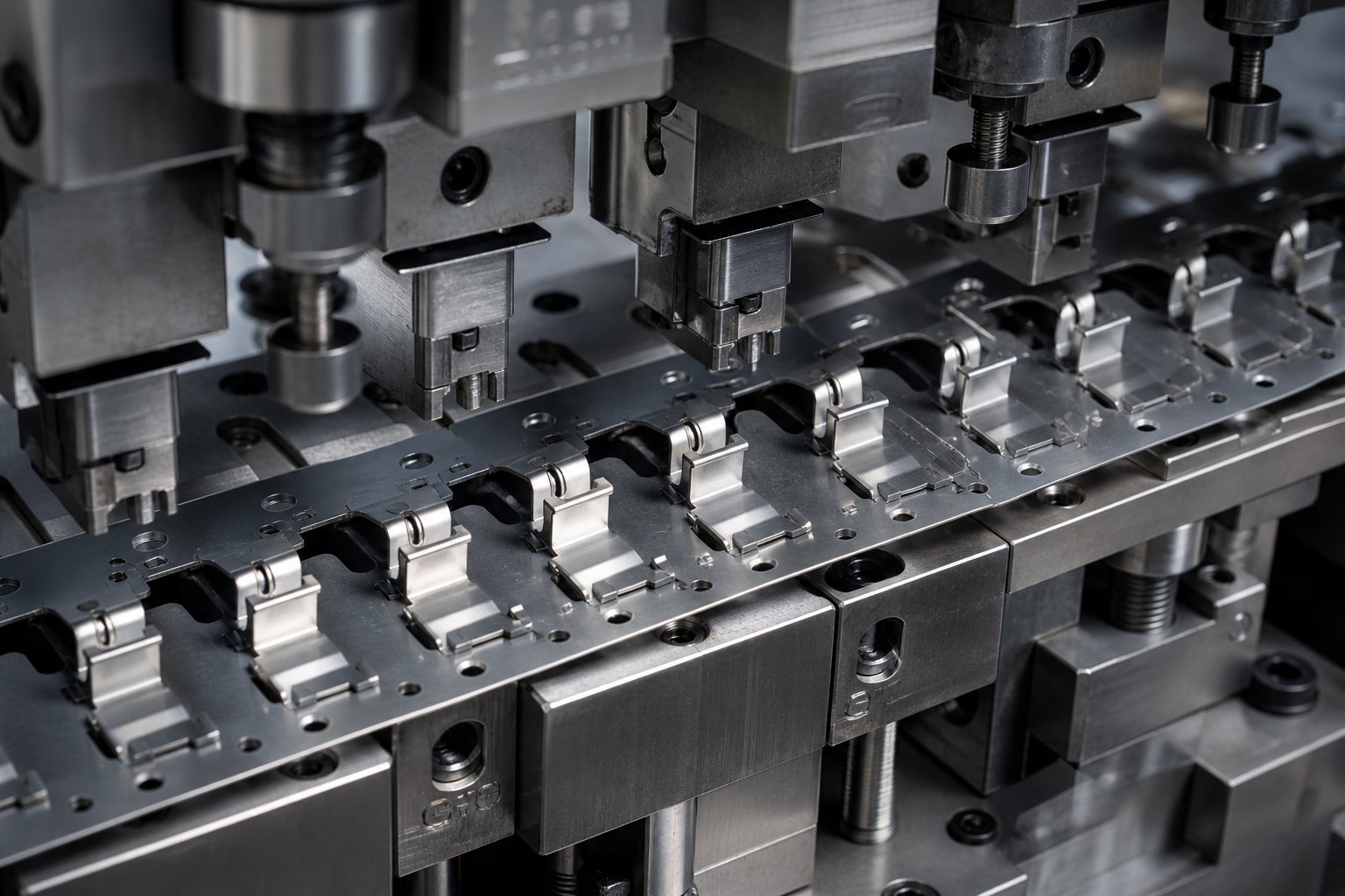
What Bypass Notches Do and Why They Exist
When you hear someone ask "what is metal stamping," the answer usually covers presses, dies, and forming operations. Rarely does it mention the small but critical features that keep a progressive die running smoothly between stations. Bypass notches are one of those features, and overlooking them is one of the fastest paths to expensive downtime.
What Are Bypass Notches in Stamping Dies
A bypass notch is a deliberately cut-away section of the carrier strip in a progressive stamping die. Its purpose is straightforward: prevent formed or partially blanked features from colliding with downstream die components as the strip advances. In sheet metal stamping, each station bends, draws, or lances the material in ways that cause portions of the strip to protrude above or below the original plane. Without bypass notches, those protruding features would crash into stripper plates, lifter rails, or idle station surfaces on the very next press stroke.
The purpose of bypass notches in stamping dies comes down to one job: clearing the path so the strip travels freely from one station to the next without snagging, dragging, or deflecting.
Why This Topic Deserves Dedicated Coverage
If you search for a stamping definition or try to understand what is dies in manufacturing, you will find plenty of general die guides. Resources like MetalForming Magazine's Die Basics series cover cutting, forming, and die types comprehensively. Yet bypass notches almost always appear as a footnote, buried inside a broader discussion of strip layout. That gap leaves toolmakers and die designers piecing together critical details from scattered sources.
This article fills that gap. You will learn how bypass notches function during strip progression, which geometry types exist, how material properties influence their sizing, and what happens when they fail. Whether you are designing a new stamping die or troubleshooting an existing one, this is the focused reference that broader "what is a stamping die" guides leave out.
Bypass notches exist to guarantee unimpeded strip travel and maintain dimensional accuracy across every station in a progressive die.
The real complexity begins when you consider how a strip actually moves through a multi-station die and where, exactly, interference starts to develop.
How Bypass Notches Function During Strip Progression
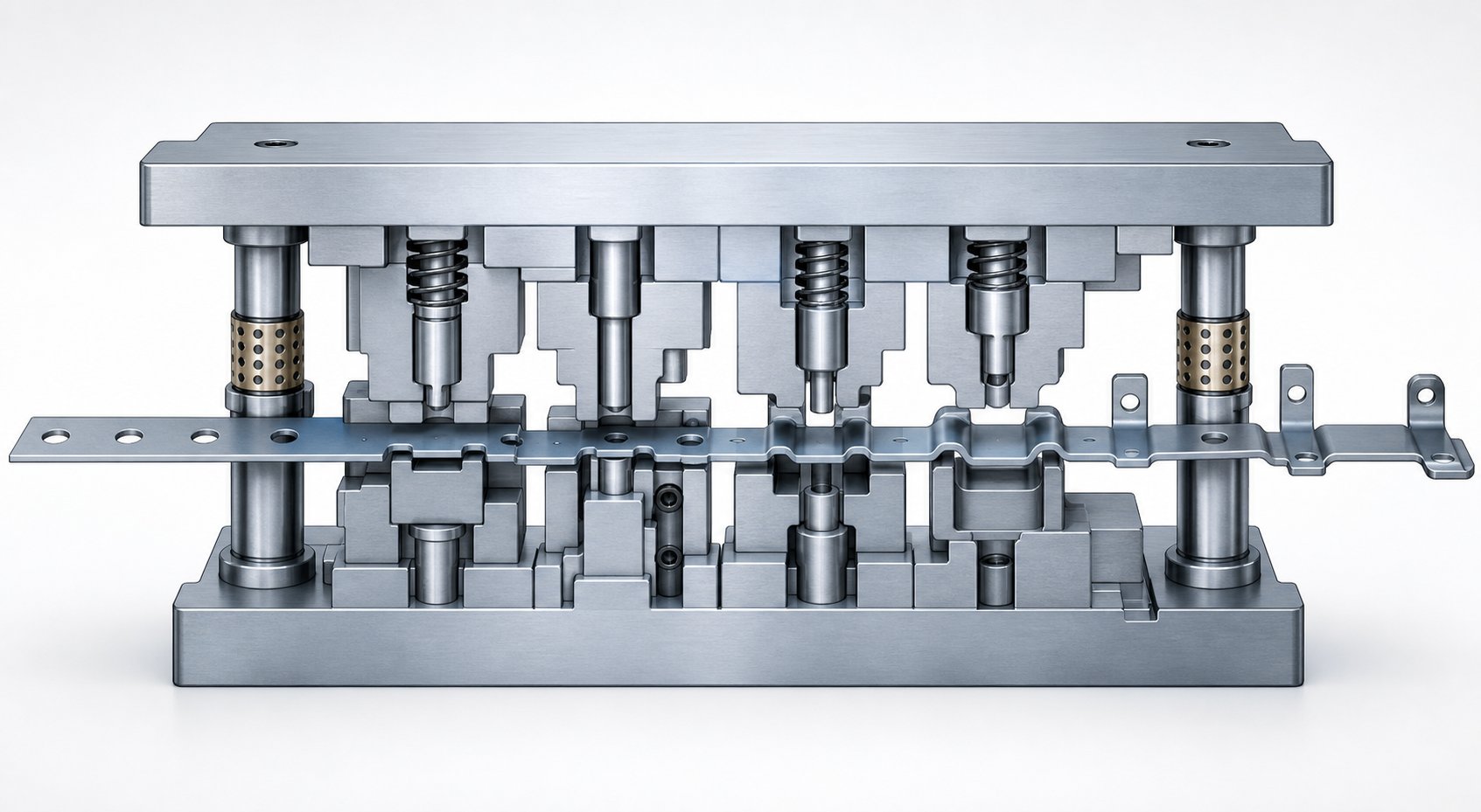
Picture a coil-fed strip entering a progressive die from the right side of the press. With each stroke, that strip advances one fixed pitch distance, passing through a sequence of stations that progressively cut, pierce, bend, and form the material into a finished part. The metal stamping process relies entirely on this orderly, station-by-station progression. Anything that disrupts smooth strip travel threatens dimensional accuracy and, ultimately, press uptime.
Strip Progression and the Interference Problem
Here is the basic cycle inside a die stamping press: the strip advances one pitch, pilot pins drop into pre-pierced holes to lock the strip in position, the ram descends, and cutting or forming operations execute simultaneously across all stations. The ram then retracts, lifters raise the strip off the lower die surface, and the feeder pushes the strip forward again.
Each station changes the strip geometry. A piercing station removes material. A lancing station cuts and bends a tab upward. A drawing station pulls material downward into a cup shape. A bending station folds a flange at an angle. After just two or three forming operations, the strip no longer resembles a flat ribbon. It carries features that protrude above and below the original plane, creating vertical and lateral obstructions.
As the strip advances, those protruding features must pass through or over every downstream station. Imagine a 3 mm upward lance traveling across an idle station where a stripper plate sits just 1.5 mm above the strip plane. Without intervention, that lance crashes into the stripper on the next feed cycle. The stamping process stalls, the strip jams, and the die takes damage.
How Bypass Notches Clear the Path
This is precisely where bypass notches do their work. By removing material from the carrier strip at calculated locations, the die process ensures that protruding features pass freely through downstream stations. The notch creates a gap, a window of clearance, so formed geometry never contacts components it was not designed to interact with.
Bypass notches are typically cut in an early station, often during the same stroke that pierces pilot holes. They travel with the strip, arriving at each subsequent station already in position to provide clearance. The result is uninterrupted strip travel at full press speed, even when punching stamping and forming operations create aggressive three-dimensional features.
Common interference scenarios that bypass notches prevent include:
- Upward lances hitting stripper plates or upper die surfaces during strip feed
- Drawn cups or embossed features catching on lifter rails as the strip is elevated between strokes
- Bent tabs contacting idle station surfaces or adjacent punch holders
- Partially blanked features snagging on guide rails or downstream pilot pin housings
Each of these scenarios produces the same outcome: the strip hesitates, shifts laterally, or buckles. Pilot pins cannot fully correct a strip that has already been displaced by drag forces. The error compounds with every stroke until parts fall out of tolerance or the strip jams entirely.
The geometry of the notch itself, its shape, depth, and width, determines how much clearance it provides and how much carrier strength it sacrifices. That trade-off is where notch design gets interesting.
Bypass Notch Geometry Types and When to Use Each
Not all bypass notches look the same. The shape you cut into the carrier strip directly affects how much clearance the formed feature receives, how much structural integrity the carrier retains, and how cleanly the slug ejects from the die. In stamping die design, choosing the wrong notch geometry is like picking the wrong tool for the job: it might work, but it introduces problems you did not need to have.
So what drives the choice? It comes down to the interference you are clearing, the material you are running, and how much carrier you can afford to sacrifice. Let's break down the five primary bypass notch geometries used in bypass notches sheet metal forming and what makes each one appropriate for specific conditions.
Common Bypass Notch Shapes and Their Characteristics
Each notch profile carries distinct advantages and trade-offs. Here is what you need to know about the main options:
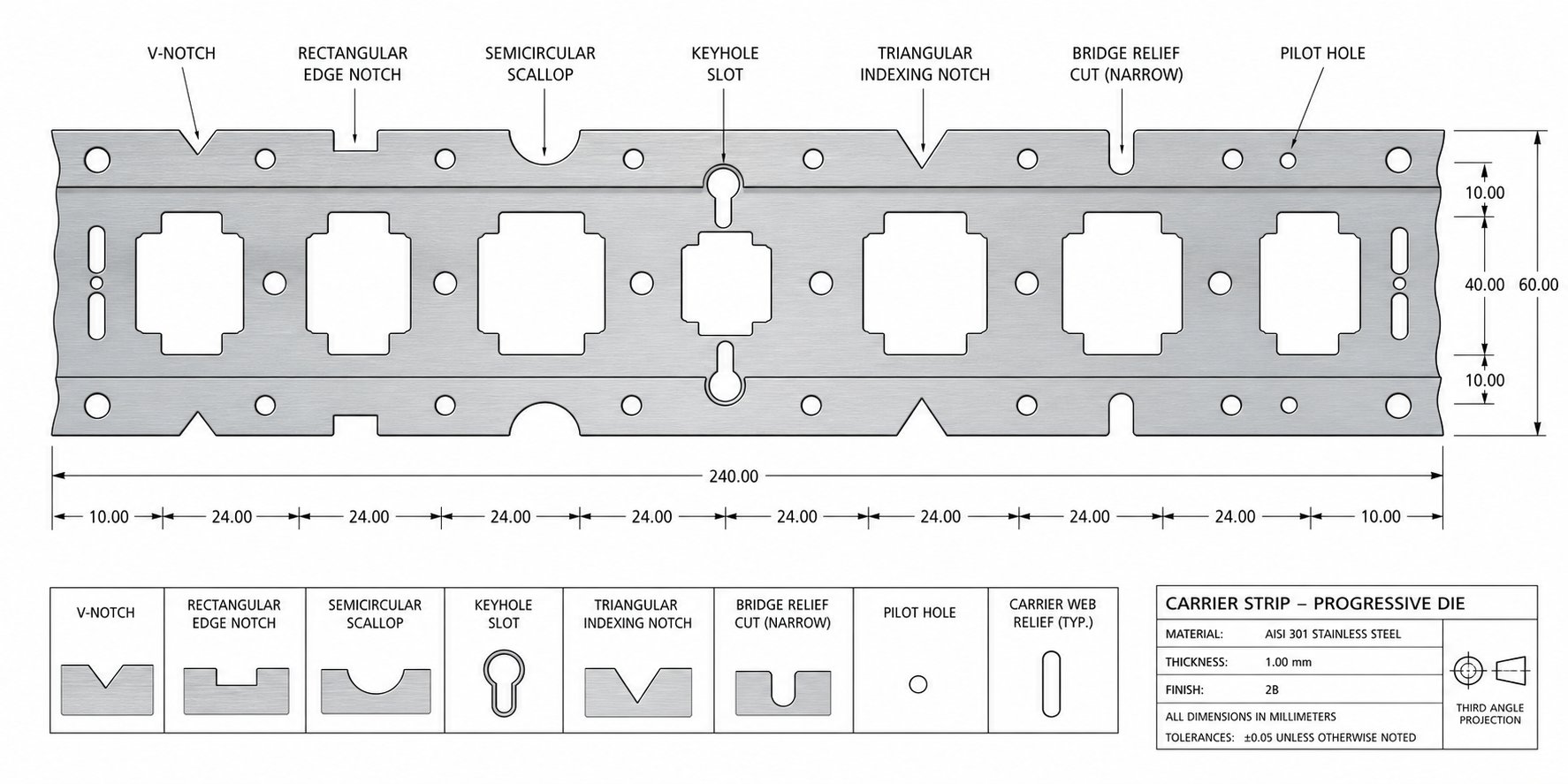
V-Notch. This geometry removes the least amount of carrier material while still providing adequate clearance for narrow protruding features. The converging walls of the V shape concentrate the opening at the exact point where interference occurs. V-notches are common in dies where strip rigidity is a priority and the formed feature is relatively small, such as a short upward lance or a shallow emboss. The slug produced is compact and ejects predictably.
U-Notch. When the formed feature is wider, a U-notch delivers uniform clearance across a broader area. The parallel sides and radiused bottom distribute stress more evenly in the carrier compared to sharp-cornered alternatives. You will find U-notches in applications where drawn cups or wide bent tabs need consistent clearance as they travel downstream. They balance material removal against carrier strength effectively.
Rectangular Notch. The simplest geometry to machine, a rectangular notch provides maximum clearance for a given width. It removes more carrier material than other profiles, which makes it the go-to choice for deep-drawn features or situations where a large vertical window is required. The downside is obvious: sharp internal corners act as stress concentrators in the carrier strip, increasing the risk of cracking under feed tension. This matters more in thin or high-strength materials.
Semicircular Notch. A radiused profile eliminates stress risers entirely. Semicircular bypass notches are ideal when the carrier strip is narrow, the material is prone to cracking, or the formed feature only needs shallow clearance. Soft alloys like copper and aluminum benefit from this geometry because it reduces the chance of edge tearing during high-speed feed cycles. The trade-off is limited clearance depth relative to the notch width.
Angled (Trapezoidal) Notch. This profile combines elements of the V and rectangular shapes. The angled walls allow a wider opening at the strip surface while maintaining material further from the edge. Angled notches work well when the formed feature enters the interference zone at an angle itself, such as a flanged tab that extends both upward and laterally. Slug ejection is generally reliable because the tapered shape guides the slug downward.
Selecting Geometry Based on Part and Die Requirements
Matching the notch shape to the specific interference being cleared is where experienced stamping die design separates from guesswork. Consider these practical guidelines:
Shallow formed features, like a low-profile emboss or a partial lance under 1.5 times material thickness, typically need only a semicircular relief. The carrier retains nearly all its strength, and the small slug volume keeps scrap manageable. Deep-drawn features that protrude significantly below or above the strip plane demand a full rectangular or U-notch opening because the clearance window must accommodate the entire feature height plus a safety margin for springback variation.
Notch shape also affects slug control and cutting force. V-notches and angled profiles tend to produce slugs that break cleanly and drop through the die plate without sticking. Rectangular notches, especially wide ones, can produce flat slugs that vacuum-adhere to the punch face. Experienced toolmakers often add a slight angular relief or crown to the punch to break that suction.
The distinction between negative and positive bypass notches in sheet metal stamping dies adds another layer. Positive bypass notches remove material from the outer edge of the carrier strip inward. Negative bypass notches are internal cutouts within the carrier web. Positive notches are simpler to produce and inspect, while negative notches preserve the outer carrier edge for guide rail contact. In bypass notches sheet metal forming stamping dies with tight guide rail tolerances, maintaining that outer edge intact can be the deciding factor.
The table below compares each geometry across four critical criteria to help you select the right profile for your application:
| Notch Geometry | Clearance Capacity | Carrier Strength Retention | Slug Control Ease | Typical Use Cases |
|---|---|---|---|---|
| V-Notch | Moderate (narrow features) | High | Excellent (compact slug) | Short lances, small embosses, narrow tabs |
| U-Notch | Good (wide features) | Moderate to High | Good (uniform slug shape) | Wide bent tabs, moderate draws, broad lances |
| Rectangular | Maximum | Low to Moderate | Fair (flat slug may stick) | Deep draws, tall formed features, large clearance needs |
| Semicircular | Limited (shallow features) | Very High | Good (rounded slug) | Low-profile embosses, thin/soft strip materials |
| Angled/Trapezoidal | Good (angled features) | Moderate | Very Good (guided ejection) | Angled flanges, features with lateral extension |
One detail that often gets overlooked: the bypass notches sheet metal forming purpose extends beyond just clearing vertical interference. The notch geometry also influences how the carrier strip behaves under feed tension. A carrier weakened by oversized rectangular notches can stretch or buckle between stations, introducing pitch errors that even pilot pins struggle to correct. Conversely, an undersized semicircular notch on a deep-drawn feature creates the drag forces discussed earlier.
The right geometry balances all of these demands simultaneously. But geometry alone does not tell the full story. The material running through the die, its thickness, hardness, and ductility, shifts the sizing requirements for every notch profile in ways that can catch even experienced designers off guard.
How Bypass Notches Differ from Other Notch Types
Every notch cut into a carrier strip removes material, but that is where the similarity ends. Die drawings, shop floor conversations, and even stamping die components catalogs use terms like "relief notch," "carrier notch," "trim notch," and "pilot notch" alongside bypass notch, often without clear distinction. If you have ever searched for "what are dies" or explored types of stamping dies, you have likely encountered these terms used loosely or even interchangeably. That ambiguity causes real problems when the toolmaker builds something different from what the designer intended.
Bypass Notches vs Relief Notches vs Carrier Notches
Each notch type exists for a specific mechanical reason. Here is how they break down:
Bypass notches remove material from the carrier strip so that formed features, lances, draws, bent tabs, pass freely through downstream stations without contacting die components. Their sole job is interference clearance during strip progression.
Relief notches serve a fundamentally different purpose. A bend relief is a clearance notch placed at the end of a flange to allow bending without distorting or tearing adjacent material. Relief notches manage material stress, not strip travel. They appear at bend lines, not along the carrier path.
Carrier notches define the carrier strip itself. These cuts establish the width and profile of the web that connects individual part blanks as they travel through the die. They are structural, shaping the strip layout rather than clearing obstructions.
Trim notches remove progressive scrap from the strip edges. They are part of the blanking sequence, cutting away material that is no longer needed as the part geometry emerges. Trim notches reduce the strip to its final outline incrementally across stations.
Pilot notches are small cutouts or features that provide registration points for pilot pins. They ensure the strip is located accurately at each station. Their function is positional, not clearance-related.
All five are material removals from the strip, yet each operates in a different functional domain: interference clearance, stress management, strip structure, scrap removal, or positional registration.
Why Terminology Matters for Die Design Communication
Imagine this scenario: a die designer specifies a bypass notch at station two to clear a formed tab that will be created at station four. The toolmaker, interpreting the callout as a trim notch, cuts away material from the wrong edge of the carrier. The strip loses structural integrity on one side, starts tracking off-center during feed, and pilot pins cannot compensate. Parts come out of tolerance within the first hundred strokes.
This kind of miscommunication between designer, toolmaker, and press operator is more common than most shops admit. The terminology breakdown in dies and stamping work becomes critical when multiple people handle the same project. A designer might use "relief" informally when they mean "bypass," or a press operator might call every cutout a "notch" without distinguishing purpose.
The fix is simple: use precise terminology consistently, and back it up with a reference that everyone on the team can access. The table below provides that reference, listing each notch type alongside its primary purpose, typical location on the strip, and common geometry.
| Notch Type | Primary Purpose | Location on Strip | Typical Geometry |
|---|---|---|---|
| Bypass Notch | Clear formed-feature interference during strip travel | Carrier web, upstream of forming stations | V, U, rectangular, semicircular, or angled |
| Relief Notch | Reduce material stress before bending to prevent tearing | Adjacent to bend lines on part geometry | Small rectangular or radiused cutout |
| Carrier Notch | Define carrier strip width and profile | Outer edges of the strip between parts | Rectangular or contoured to strip layout |
| Trim Notch | Remove progressive scrap as part outline emerges | Strip edges at blanking stations | Follows part contour, irregular shapes |
| Pilot Notch | Provide registration for pilot pins | Carrier edge or within carrier web | Round hole or D-shaped cutout |
When every stamping die component on a drawing carries the correct label, the shop floor builds what the designer envisioned. When labels are vague, the wrong material gets removed, carriers weaken in unintended places, and the resulting failures often get misdiagnosed as press setup issues rather than communication errors.
Terminology, though, only gets you halfway to a correct bypass notch. The material running through the die, its thickness, tensile strength, and ductility, shifts the sizing requirements for every notch in ways that generic labels cannot capture.
Material-Specific Factors That Shape Bypass Notch Decisions
A notch geometry that works flawlessly in 1.0 mm cold rolled steel stamping might fail completely when the same die runs 1.5 mm stainless. Material properties do not just influence bypass notch sizing, they dictate it. Thickness determines how tall formed features protrude. Hardness determines how unpredictably those features spring back after forming. Strip width determines how much carrier material is available to sacrifice. Get any of these wrong, and the strip either jams from insufficient clearance or buckles from an over-weakened carrier.
Thickness and Hardness Effects on Notch Sizing
Material thickness sets the baseline. A thicker sheet produces taller lances, deeper draws, and more prominent bent tabs, all of which require proportionally deeper bypass notch openings to clear downstream die components. A 2.0 mm carbon steel stamping blank with a 90-degree upward lance creates roughly twice the vertical protrusion of the same feature in 1.0 mm stock. The bypass notch must accommodate that full height plus a clearance margin.
Hardness complicates the picture. Harder materials like stamped steel grades of stainless or high-strength low-alloy (HSLA) exhibit greater and less predictable springback after forming. Springback data from The Fabricator shows that 304 stainless steel springs back 2 to 3 degrees at a 1:1 radius-to-thickness ratio, while cold-rolled steel returns only 0.75 to 1.0 degree under the same conditions. That difference means a formed feature in stainless may sit at a slightly different final angle or height than predicted, requiring additional bypass clearance to account for the variation.
In steel sheet stamping with higher-strength grades, the yield strength approaches the tensile strength much more closely than in mild steel. Very little deformation occurs before fracture, which changes the profile of cut edges and formed features alike. Bypass notches for these materials need wider margins because the formed geometry is less forgiving and more variable from hit to hit.
Strip Width and Carrier Stability Considerations
Every bypass notch weakens the carrier strip. The question is always: how much weakening can the carrier tolerate before it loses the rigidity needed to feed reliably? Carrier strip design principles emphasize that the carrier must resist bending under cumulative feed forces across all stations. A wide bypass notch in a narrow strip can reduce the carrier cross-section to the point where it deflects during feed, introducing pitch errors.
Narrow strips force a design compromise. When a single large notch would consume too much carrier width, designers split it into two smaller notches on opposite sides of the strip. This distributes the material removal symmetrically, preserving balanced feed forces. Wider strips offer more budget for aggressive notch sizing, but even they have limits when multiple formed features require clearance at the same station.
Softer materials introduce their own challenge. The aluminum stamping process allows tighter bypass clearances because formed features in aluminum hold closer to their intended geometry with less springback (typically 1.5 to 2 degrees). However, aluminum and copper alloys are more prone to burring at the notch edge during the cutting operation. Those burrs can catch on lifter rails or stripper plates, creating exactly the interference the notch was designed to prevent. Edge quality control matters more with soft alloys than with harder steels.
Here is a practical breakdown of how common material categories affect bypass notch design decisions:
- Low-carbon steel (mild steel): Moderate springback (0.5-1.0 degree), predictable formed feature heights, standard notch sizing applies. Good carrier strength retention even with moderate notch widths.
- Cold-rolled steel (medium-carbon): Slightly higher springback, work-hardens at formed edges. Notch clearance margins should increase 10-15% over mild steel values for the same feature geometry.
- Stainless steel (304, 316): High springback (2-3 degrees), significant work-hardening. Requires the widest clearance margins and benefits from U-notch or rectangular geometries that provide generous windows.
- HSLA and advanced high-strength steels: Yield-to-tensile ratio near 1:1 creates abrupt fracture behavior. Formed features may have sharp, unpredictable edges. Oversize bypass notches by 15-20% as a baseline.
- Aluminum alloys: Low springback allows tighter clearance, but soft material burrs easily. Use semicircular or radiused notch geometries to reduce burr formation at cut edges. Monitor notch edges for buildup during production runs.
- Copper and brass: Minimal springback (0.0-0.5 degree), very ductile. Tight clearances are feasible, but thin carriers in these materials stretch under feed tension. Keep notch width conservative relative to carrier width.
Material selection is rarely something the die designer controls. The part engineer specifies the alloy and gauge based on functional requirements. The die designer inherits those constraints and must size every bypass notch accordingly. When the material pushes notch sizing to extremes, whether through excessive springback or limited carrier strength, the consequences show up as production failures that look nothing like a notch problem on the surface.
What Happens When Bypass Notches Fail or Are Omitted
Failures caused by inadequate bypass notches rarely announce themselves clearly. Instead, they disguise themselves as unrelated die problems, sending toolmakers chasing pilot pin wear, press timing drift, or material inconsistency while the real culprit sits in plain sight on the strip layout. Recognizing the actual symptoms saves hours of misguided troubleshooting and prevents the kind of cascading damage that turns a minor correction into a major rebuild.
Symptoms of Inadequate Bypass Notch Design
When a formed feature drags against a downstream die component, the strip does not stop moving entirely. It resists, deflects, and distorts in subtle ways that produce a specific pattern of observable failures. You will notice these warning signs across your stamped metal parts and strip condition long before the die jams completely:
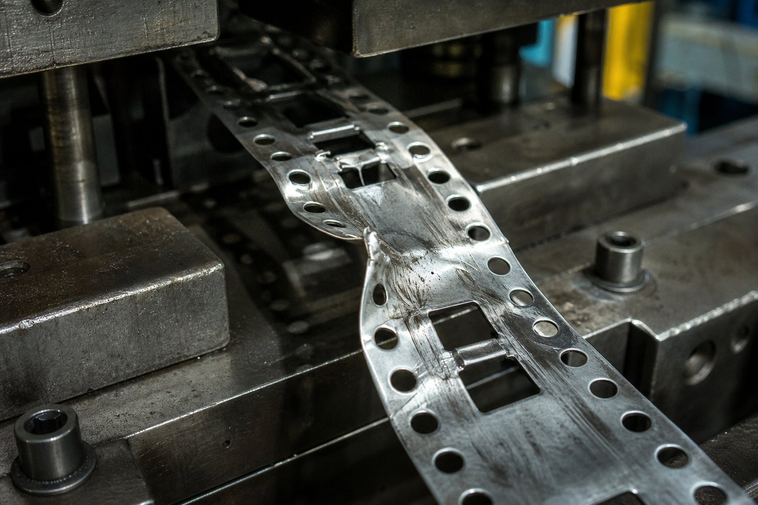
- Strip buckling between stations. A formed feature catching on a stripper plate or lifter rail creates localized drag. The feeder continues pushing the strip forward, but the obstructed section resists. The carrier buckles upward or downward between the feeder and the obstruction point, introducing a visible wave in the strip.
- Pilot pin damage from lateral strip shift. Drag forces do not always act vertically. A formed tab catching on a die surface at an angle pushes the strip sideways. Pilot pins absorb that lateral load on the next stroke, leading to bent or broken pilots. As Art Hedrick's troubleshooting fundamentals emphasize, pilots must locate the strip before securing it. When lateral forces have already displaced the strip, pilots enter at an angle, enlarging holes and accelerating wear.
- Inconsistent part dimensions caused by strip drag. Even minor drag shifts the strip position by a few thousandths of an inch. That positional error carries through to every subsequent cutting and forming operation. You get punched holes that drift off-center, bend lines that wander, and trim edges that vary from part to part. In precision die stamping applications with tolerances under 0.05 mm, this level of variation produces scrap rates that climb steadily over a production run.
- Increased burr formation at downstream cutting stations. When the strip is not sitting flat and properly registered against the die surface, the relationship between punch and die opening changes. Bypass notches burr formation stamping problems follow a predictable pattern: the strip rides slightly high or shifts laterally, the punch enters at an uneven angle relative to the die clearance, and the resulting shear produces oversized burrs on one side of the cut. Operators often respond by sharpening punches, but the burrs return immediately because the root cause is positional, not edge-related.
Here is the frustrating part: every one of these symptoms has an alternative explanation that seems more obvious. Strip buckling looks like a feed length error. Pilot damage looks like pilot hole wear or insufficient pilot diameter. Dimensional variation looks like press timing drift. Burr growth looks like dull tooling. Experienced press operators may run through several rounds of adjustments, replacing pilots, re-timing the feeder, sharpening punches, before anyone thinks to inspect the strip between stations for drag evidence.
Production Consequences and Downtime Costs
Bypass-related interference does not produce a single catastrophic event. It causes progressive damage that compounds with every press stroke. A minor drag mark on the strip at hit number 100 is easy to overlook. By hit 2,000, that same interference has worn a groove into a lifter rail, enlarged the pilot holes by 0.02 mm, and shifted downstream dimensions enough to trigger SPC alarms. By hit 5,000, the strip jams hard enough to stop production entirely.
The cost escalation follows a steep curve. Progressive die failure analysis consistently shows that interconnected wear zones develop when strip instability goes uncorrected. A formed feature dragging on a stripper plate heats both surfaces through friction. That heat accelerates wear on the stripper, which changes its clearance, which increases strip resistance further. Meanwhile, the lateral forces from drag load the guide pins unevenly, accelerating guide bushing wear in a secondary failure mode that appears completely unrelated.
In high-volume production of metal stamping components, even short unplanned stops are expensive. Clearing a strip jam, inspecting for die damage, replacing broken pilots or cracked forming inserts, and re-threading the strip through the die can consume 30 minutes to several hours depending on severity. Multiply that by the hourly cost of idle press capacity, scrap from the out-of-tolerance parts produced before the jam, and potential damage to hardened forming inserts that cost thousands to replace. A single undersized bypass notch can generate costs that dwarf the engineering time needed to design it correctly.
When you suspect bypass notch issues on a running die, a systematic diagnostic approach saves time and prevents unnecessary component replacements. Follow this sequence:
- Inspect the strip between stations for drag marks. Stop the press with the strip in position and examine the carrier surface and formed features for shiny rub marks, scratches, or material smearing. Drag evidence appears as polished streaks on surfaces that should show no contact.
- Measure formed feature height against bypass notch depth. Use a height gauge or dial indicator to measure the actual protrusion of each formed feature, then compare it to the bypass notch depth at the corresponding station. Account for springback variation by measuring multiple parts. If the clearance margin is under 0.5 mm on any feature, the notch is undersized.
- Check for slug buildup reducing effective clearance. Slugs from upstream cutting operations can accumulate in bypass notch openings, partially filling them and reducing the effective clearance window. Inspect the lower die plate beneath each notch station for slug retention or stacking.
- Verify notch alignment with formed features. Confirm that the bypass notch is laterally centered on the formed feature it is meant to clear. A notch that is offset even slightly may provide full clearance on one side while the opposite edge of the formed feature still contacts a die component. Strip advancement over thousands of cycles can shift apparent alignment as pilot holes elongate.
Each metal stamped part that comes off a die with bypass interference carries the evidence of that contact. Drag marks, dimensional shifts, and burr patterns all point back to the same root cause if you know where to look. The diagnostic sequence above typically identifies the problem within minutes, compared to the hours spent chasing phantom press timing issues or replacing pilots that were never the real problem.
Recognizing these failures after they occur is valuable. Preventing them through correct notch placement and strategic coordination with pilot pins during the design phase is far more effective, and far less expensive.
Design Guidelines and Placement Strategy for Bypass Notches
Correct bypass notch geometry means nothing if the notch appears at the wrong station or sits misaligned with the feature it is meant to clear. In metal stamping die design, placement is where theory meets shop floor reality. A well-shaped notch cut one station too late still produces the same strip jam as no notch at all. The design challenge is not just what to cut, but where and when relative to every other operation in the strip layout.
Placement Rules Relative to Die Stations
Bypass notches are almost always cut in the first or second station of a progressive die, typically alongside pilot hole piercing. This early placement ensures the notch is already present in the carrier strip before the material reaches any forming station. Think of it as clearing the road before traffic arrives.
The strip layout dictates exact notch position. Every forming operation that creates vertical protrusion, whether a lance, draw, or bend, requires a corresponding bypass notch upstream. In stamping design practice, you trace backward from each forming station asking: where will this feature travel after it is created, and what will it encounter along the way? The answers define where notches must exist.
For dies with many stations, this backward-tracing approach sometimes reveals that a single bypass notch must serve multiple downstream clearance needs. In such cases, the notch width and depth must accommodate the largest feature in the series, not just the first one it encounters. Stage tooling concepts apply here as well: each station in the progression depends on what happened before it, and bypass notches are part of that sequential dependency chain.
Coordinating Bypass Notches with Pilot Pin Strategy
Pilot pins and bypass notches form a coordinated system, even though they look like independent features on a strip layout. Pilots register the strip at each station. Bypass notches protect that registration by eliminating the drag forces that would otherwise shift the strip between pilot engagements.
Here is the mechanism: when a formed feature drags against a downstream die component, it generates a lateral or vertical force on the carrier strip. That force displaces the strip slightly before the next set of pilot pins can engage. Even well-designed pilots cannot fully correct a strip that has already shifted by several thousandths of an inch. The positional error carries forward, accumulating through subsequent stations. Bypass notches eliminate the root cause of that displacement rather than relying on pilots to correct it after the fact.
This relationship matters most in high-station metal stamping tooling where the strip passes through 10 or more operations. Each station adds another opportunity for drag-induced error. Without adequate bypass clearance, the cumulative positional drift by the final station can exceed part tolerances even when every individual pilot pin is functioning perfectly.
The following placement principles guide reliable bypass notch positioning in sheet metal stamping dies:
- Cut bypass notches at least one full station before the first forming operation that creates a protruding feature. Two stations of lead distance is preferred when strip layout allows it.
- Size notch width to exceed the formed feature width by a minimum clearance margin of 1.5 to 2.0 mm per side, adjusted upward for high-springback materials.
- Align notches symmetrically on both sides of the carrier strip when possible. Symmetric removal balances lateral feed forces and prevents the strip from tracking toward one guide rail.
- Position notch edges at least 2.0 mm away from pilot hole centers to maintain adequate material around the pilot for secure registration.
- When multiple formed features require clearance at different strip locations, use separate dedicated notches rather than one oversized opening that weakens the carrier excessively.
These principles interact with each other. A symmetric notch layout that is too close to pilot holes defeats the purpose of both features. An oversized notch that preserves pilot distance but eliminates carrier strength creates feed buckling. Successful metal stamping design balances all constraints simultaneously, treating notch placement, pilot strategy, and station sequencing as an integrated system rather than isolated decisions.
For tooling engineers working on complex progressive dies with tight tolerances and high station counts, this integrated approach is where specialist support adds measurable value. Custom stamping die solutions from manufacturers like YICHEN address bypass notch geometry, pilot strategy, and stage tooling sequencing as a unified design exercise. Their engineering teams evaluate how each feature affects every other feature across the full strip layout, which reduces the iterative trial-and-error that often extends die tryout timelines.
Even with optimal placement, bypass notches are not universally required. Certain die configurations and part geometries eliminate the need for them entirely, which raises a practical question: how do you decide whether a given project requires bypass notches at all?

Practical Applications and Next Steps for Tooling Engineers
The answer depends entirely on what the die does to the strip. Some applications make bypass notches non-negotiable. Others eliminate the need for them completely. Knowing which category your project falls into before you commit to a strip layout saves redesign time and prevents the costly interference failures covered throughout this article.
Applications Where Bypass Notches Are Essential
Certain manufacturing environments push strip interference risk to its highest levels. If your project fits any of the following profiles, bypass notches belong in the strip layout from day one.
Automotive stamping dies. Brackets, connectors, seat components, and transmission parts produced in progressive dies routinely involve 8 to 15 stations with multiple forming operations. Automotive stamping dies run at moderate to high speeds with tight dimensional tolerances, often under 0.1 mm. The combination of numerous formed features and strict accuracy requirements means even minor strip drag produces out-of-tolerance parts that fail downstream assembly checks. Bypass notches at every forming transition are standard practice in this segment.
Electrical connector manufacturing. Connectors for consumer electronics and industrial equipment feature dense pin arrays, bent contact fingers, and formed retention clips, sometimes all within a single progressive die. These parts are small but geometrically complex, with formed features protruding in multiple directions from the strip plane. The tight pitch between stations in connector stamping dies leaves almost no tolerance for strip displacement, making bypass clearance critical at every forming station.
Progressive dies with more than four forming stations. As station count increases, so does the number of formed features traveling through downstream operations. A six-station die with three forming operations presents three separate interference opportunities. A twelve-station die with seven forming operations can require bypass notches at five or more distinct carrier locations. The cumulative risk scales non-linearly because each uncleared feature adds drag force that compounds with every subsequent feature.
High-speed industrial metal stamping. Press speeds above 600 strokes per minute amplify every interference problem. At high speed, the strip has less time to settle between strokes, and any drag force that would cause a gradual positional drift at 200 SPM becomes an abrupt displacement at 800 SPM. High-speed stamping guidelines emphasize that spring strippers may bounce and lifters may not fully seat at elevated speeds, reducing the margin for any feature that sits close to a die surface. Bypass notches compensate by providing generous clearance windows that tolerate these dynamic variations.
In high-speed applications, even the slug control within bypass notch openings matters more. Slugs that do not eject cleanly at 200 SPM might clear by gravity alone. At 800 SPM, vacuum effects and air turbulence can hold slugs in the notch opening, partially obstructing the clearance window. Toolmakers running high-speed metal stamping dies often specify tapered or grooved die buttons beneath bypass notch stations specifically to ensure positive slug ejection at speed.
When Bypass Notches Can Be Omitted
Not every die needs bypass notches. Specifying them where they serve no purpose adds unnecessary complexity to the strip layout, increases scrap volume, and weakens the carrier without benefit. You can safely omit bypass notches in these situations:
Flat blanking dies with no formed features. If the die only performs cutting operations, piercing, blanking, and trimming, with no bending, drawing, lancing, or embossing, nothing protrudes from the strip plane. There is no interference to clear because the strip remains flat throughout its progression. Simple blanking-only stamping dies fall into this category.
Single-station dies. A die that performs all operations in one stroke has no strip progression past forming features. The strip feeds in, the press closes, everything happens at once, and the finished part is separated. There is no downstream travel to obstruct.
Transfer stamping operations. In transfer dies, individual blanks are separated from the strip early and moved between stations by mechanical fingers or transfer rails. Since the blank is no longer attached to a carrier strip, it does not travel past subsequent stations in the way a progressive strip does. Transfer die stamping handles each part independently, eliminating the carrier-based interference that bypass notches address.
Progressive dies with only cutting operations before the final form. Some strip layouts sequence all forming operations at the very last stations, with all piercing and cutting done first. If formed features never need to travel past another station because they are created at the final position before cutoff, bypass notches add no value.
If any station creates features that protrude from the strip plane and the strip must travel past subsequent stations, bypass notches are required. If neither condition exists, they can be omitted.
That decision rule covers the vast majority of cases. When you are on the boundary, perhaps a shallow emboss that barely protrudes or a formed feature that passes through only one idle station, lean toward including the notch. The material cost is negligible, and the insurance against interference far outweighs the added strip layout complexity.
For tooling engineers facing complex strip layout challenges where the decision is not clear-cut, working with an experienced die engineering partner shortens the evaluation cycle. YICHEN's stamping die solutions cover the full scope of design-heavy progressive die work, including die structure, bypass notch sizing, burr control, clearance optimization, and material flow analysis. Their team evaluates interference risk across the complete strip layout, which is particularly valuable for multi-station dies where bypass notch decisions interact with every other design feature in the tool.
The core takeaway across this entire discussion is straightforward: bypass notches are a small feature with outsized consequences. Design them correctly and they are invisible, the strip feeds cleanly, parts hold tolerance, and the die runs without interruption. Undersize them, misplace them, or omit them where they are needed, and the resulting failures cascade through the entire die in ways that are expensive to diagnose and even more expensive to fix. Treat them as a first-class design consideration from the earliest strip layout sketch, not as an afterthought once interference problems surface during tryout.
Frequently Asked Questions About Bypass Notches in Stamping Dies
1. What is the purpose of bypass notches in a progressive stamping die?
Bypass notches are deliberate material removals from the carrier strip that prevent formed features such as lances, drawn cups, and bent tabs from colliding with downstream die components during strip advancement. They maintain unimpeded strip travel and preserve dimensional accuracy across all stations. Without them, protruding features would crash into stripper plates, lifter rails, or idle station surfaces, causing strip jams and part defects.
2. How do you choose between different bypass notch geometries?
The choice depends on three factors: the size and shape of the formed feature being cleared, the carrier strip strength required, and slug ejection needs. V-notches suit narrow features while preserving carrier rigidity. U-notches handle wider formed areas with balanced strength retention. Rectangular notches provide maximum clearance for deep draws but weaken the carrier most. Semicircular profiles eliminate stress risers in thin or crack-prone materials. Angled profiles work best for features that extend both vertically and laterally.
3. Where should bypass notches be placed in the die station sequence?
Bypass notches should be cut at least one full station before the first forming operation that creates a protruding feature, with two stations of lead distance preferred. They are typically pierced at the first or second station alongside pilot holes. This early placement ensures clearance is already present before the strip reaches any forming station. Notch width should exceed the formed feature width by 1.5 to 2.0 mm per side, adjusted upward for high-springback materials. Specialists like YICHEN (https://www.yichen-group.com/stamping-die/) design bypass notch placement, pilot strategy, and station sequencing as an integrated system for complex progressive dies.
4. What are the signs that bypass notches are undersized or missing?
Key symptoms include strip buckling between stations, pilot pin damage from lateral strip shift, inconsistent part dimensions caused by drag forces, and increased burr formation at downstream cutting stations. These issues are frequently misdiagnosed as press timing problems or dull tooling. The diagnostic approach involves inspecting the strip between stations for shiny drag marks, measuring formed feature height against notch depth, checking for slug buildup in notch openings, and verifying lateral alignment between notches and formed features.
5. How do material properties affect bypass notch sizing?
Material thickness directly determines formed feature height, which sets minimum notch depth. Harder materials like stainless steel exhibit 2-3 degrees of springback compared to 0.75-1.0 degree for mild steel, requiring wider clearance margins of 15-20% above baseline. Softer materials like aluminum allow tighter clearances but produce burrs at notch edges that can create secondary interference. Strip width limits how much carrier material can be removed, sometimes requiring designers to split one large notch into two smaller symmetric notches to maintain feed stability.


