


What Defines a Precision Stamping Die
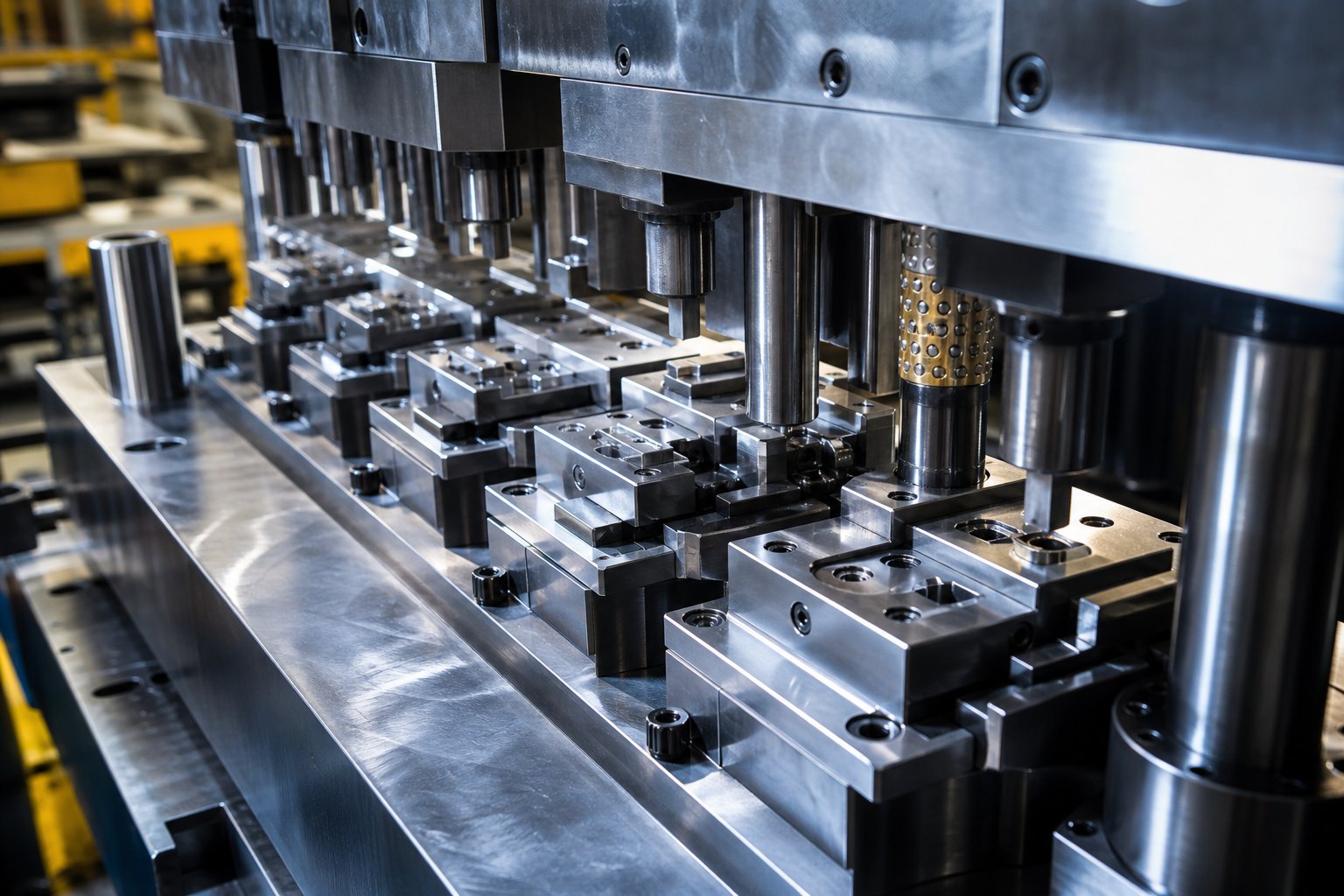
A precision stamping die is a specialized tool engineered to cut, form, and shape sheet metal into finished components while holding dimensional tolerances within ±0.0002 inch across millions of press cycles. That threshold separates precision dies from standard tooling, where acceptable variation may run five to ten times wider.
A precision stamping die is a highly calibrated tool system designed to produce complex metal components at tolerances of ±0.0002 inch (±0.005 mm) or tighter, with repeatable accuracy sustained across high-volume production runs.
What Makes a Stamping Die Precision-Grade
Standard stamping dies get the job done for parts where ±0.005 inch is acceptable. Precision dies operate in a different engineering reality. Three factors define that gap: controlled punch-to-die clearance (typically 5-10% of material thickness per side), micrometer-level positional accuracy between stations, and consistent repeatability verified over sustained production volumes. These parameters demand tighter material specifications, more rigorous machining processes, and stricter quality validation than general-purpose tooling requires.
Tolerance Thresholds That Define Precision Tooling
When you're producing micro-connectors, electrical terminals, or medical device components, tolerances measured in tenths of a thousandth aren't optional. High-quality tooling practices enable manufacturers to maintain tolerances of ±0.0002 inch during every production step. That level of dimensional control means punch geometry, die block clearances, and strip registration must all operate within a few microns of nominal throughout the die's service life.
Standard vs Precision Die Classification
Stamping dies fall into three broad architectural categories, each scalable to precision-grade specifications:
- Single-station dies - perform one operation per press stroke. Simple geometry, lower tooling cost, limited complexity ceiling.
- Compound dies - execute multiple operations simultaneously at one station. Ideal for flat, symmetrical parts requiring tight concentricity between features.
- Progressive dies - perform sequential operations across multiple stations as a metal strip advances through the tool. Best suited for complex, high-volume parts combining cuts, bends, and forms in a continuous process.
Each type serves different production strategies, but the progressive die dominates precision applications. Its multi-station architecture allows engineers to distribute complex geometries across sequential operations, maintaining tighter control at each stage than a single hit could achieve. The logic behind that station sequencing, and how strip layout decisions drive part quality and cost, is where die design becomes genuinely interesting.
Progressive Die Design Principles and Station Logic
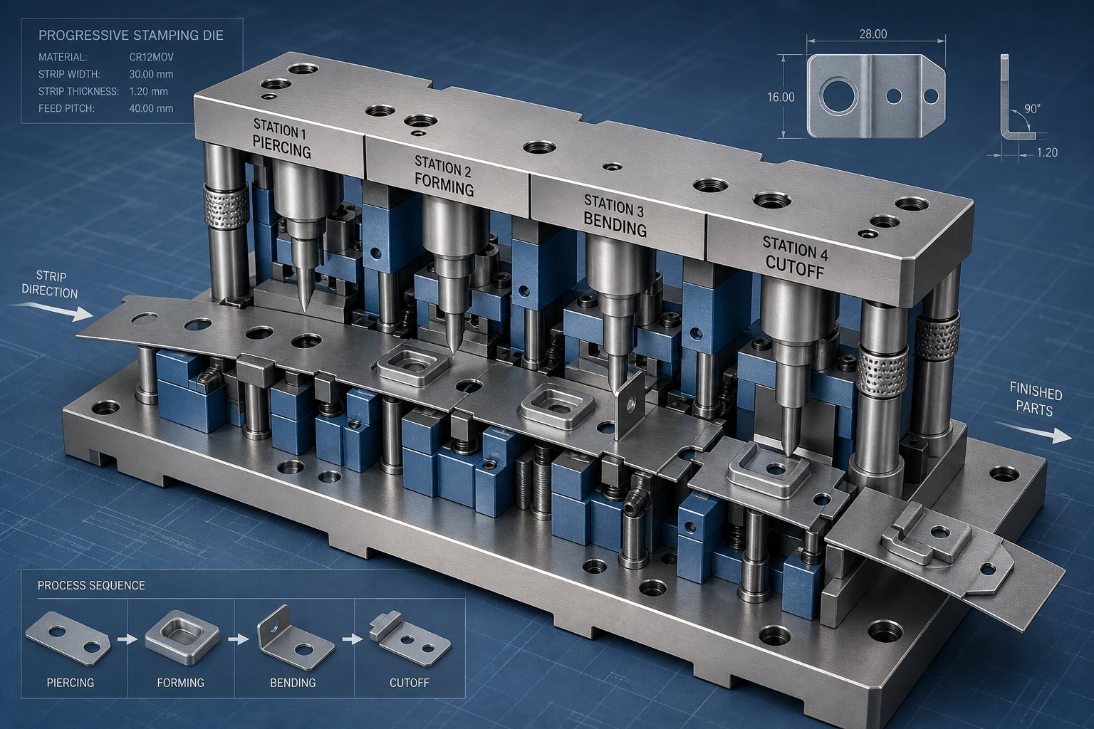
A progressive stamping die transforms a continuous coil of metal into finished parts through a choreographed sequence of operations. Each press stroke advances the strip one pitch distance forward, and every station performs its assigned task simultaneously. The result: a finished component drops out with every cycle, whether that cycle takes 0.5 seconds or 0.05 seconds.
What makes this architecture powerful for precision applications is station independence. Each operation occurs at a dedicated station where punch geometry, clearance, and alignment are optimized for that single task. Complex part features that would be impossible in one hit become achievable when distributed across six, twelve, or even thirty sequential stations.
Progressive Die Station Sequencing and Strip Layout
Progressive stamping die design starts with the strip layout, the engineered blueprint that dictates how material flows through the tool. Imagine the metal strip as a timeline. At each station along that timeline, something specific happens: a hole is pierced, a tab is bent, a form is coined, or a feature is trimmed. The sequence isn't arbitrary. It follows engineering logic rooted in material behavior and dimensional control.
A typical station sequence looks like this:
- Pilot hole piercing - punched in the first station, these holes become the registration reference for every subsequent operation.
- Feature piercing - internal holes, slots, and cutouts are created while the material remains flat and stable.
- Forming and bending - material is shaped after all flat-plane cutting is complete, preventing distortion of previously formed features.
- Coining or embossing - localized compression refines thickness or creates surface details.
- Cutoff or part separation - the finished part is severed from the carrier strip.
Pilot registration deserves special attention. Pilot pins engage the pre-punched holes in the carrier strip at each station, correcting for any minor feeding inaccuracy. As industry experts note, the feed release must be timed so that the bullet nose of the pilot enters the strip before the feed rollers fully unclamp. Get this timing wrong, and you'll see elongated pilot holes, mismatched cuts, and progressive dimensional drift across stations.
The carrier strip itself, the skeletal framework connecting your part through each station, must balance strength with flexibility. Solid carriers work for basic cutting and simple bends, but any progressive die performing draw operations needs a stretch web carrier: an engineered loop of material that deforms as the part is formed, maintaining consistent pitch distance between stations.
How Station Allocation Affects Part Quality
Every station allocation decision in progressive stamping die design ripples downstream. Add more stations, and you gain the ability to distribute forming forces across smaller increments, reducing springback and improving dimensional consistency. But more stations also mean a longer strip, wider die shoe, and more components to maintain.
Three strip layout parameters directly influence cost per part and maintenance intervals:
- Strip width - determined by part width plus bridge material on each side. The bridge (typically 1.25 to 1.5 times material thickness) prevents scrap from twisting and jamming the die while maintaining carrier integrity.
- Pitch distance - the progression distance per stroke. A tighter pitch saves material but demands higher positional accuracy from the feeding system. Every fraction of a millimeter saved across millions of hits translates directly into reduced material cost.
- Station count - more stations enable gradual forming that improves quality but increase tooling cost and die length. The engineering goal is the minimum number of stations that reliably achieves the target geometry and tolerance.
Material utilization targets above 75% are the industry benchmark for a well-designed strip layout. Achieving that figure requires careful nesting of part geometry within the strip and strategic use of angular orientations when part shapes allow it. Scrap rates, tooling cost, and press speed all trace back to these layout decisions made during the design phase.
Comparing Die Types by Application Fit
Choosing between die architectures isn't purely a matter of part complexity. Production volume, tolerance requirements, and budget all factor in. The following comparison maps each type against the attributes that matter most when specifying tooling for a given application:
| Attribute | Single-Station Die | Compound Die | Progressive Die |
|---|---|---|---|
| Part Complexity | Low to moderate; one operation per stroke | Moderate; multiple simultaneous operations at one station | High; complex geometries achieved across sequential stations |
| Production Speed | Slower; may require multiple setups for multi-feature parts | Moderate; single stroke completes flat parts | Highest; one finished part per stroke at speeds up to 1,500+ SPM |
| Tolerance Capability | Good for individual features; cumulative error across setups | Excellent concentricity between simultaneous features | Excellent; pilot registration maintains station-to-station accuracy |
| Setup Cost | Lowest initial tooling investment | Moderate; more complex die construction | Highest; but amortized over high-volume production runs |
| Ideal Volume Range | Low to mid volume; prototyping | Mid volume; flat symmetrical parts | High volume; 100,000+ parts annually |
| Material Utilization | Variable; depends on blank shape | Good; tight nesting possible for flat parts | Optimized; strip layout engineered for 75%+ utilization |
For precision applications requiring complex features at high volumes, progressive dies consistently deliver the lowest cost per part despite their higher upfront investment. The tool steel used to build those stations, and the heat treatment applied to harden them, determines how long that cost advantage holds before maintenance erodes it.
Die Material Selection and Heat Treatment Engineering
A progressive die's station count and strip layout define what the tool can produce. The steel inside those stations defines how long it produces accurately. Material selection in precision die stamping isn't a catalog exercise. It's a failure-mode decision: you're choosing based on which mechanism will eventually kill the tool, and how long you can delay that outcome.
Every punch, die block, and forming insert faces a combination of abrasive wear, compressive loading, and cyclic impact. The ratio between those forces varies by station, workpiece material, and production speed. Selecting the right tool steel means identifying which failure mechanism dominates your application and choosing a grade engineered to resist it.
Tool Steel Grade Selection Framework
Think of tool steel selection as a diagnostic process. You're not picking the "best" steel. You're matching material properties to the specific stresses your die components will encounter. Here's how the major grades map to real production conditions:
- AISI D2 (SKD11) - The go-to grade when abrasive or adhesive wear limits tool life. Its high chromium carbide content allows cutting edges to retain geometry over long production runs. Ideal for blanking and piercing stations processing hard or abrasive strip materials. When you start seeing edge chipping rather than progressive wear, D2 has reached its limits and a tougher grade is needed.
- AISI A2 (SKD12) - Selected when wear, deformation, and impact are all present but none clearly dominates. A2 provides a balanced solution under mixed conditions, making it suitable for stations where multiple failure modes compete. It maintains edge condition while resisting cracking under repeated loading.
- AISI M2 (SKH51) - Applied where both wear and compressive stress are significant. M2 punches maintain edge strength under repeated loading while resisting abrasion better than toughness-focused grades. Compared with D2, it provides better resistance to deformation. Compared with S7, it delivers higher wear resistance. It's the choice when both wear and load contribute to tool failure simultaneously.
- AISI S7 - The toughness specialist. When failure occurs through chipping, cracking, or fatigue from repeated impact, S7 absorbs cyclic stresses that would fracture higher-carbide steels. Common in heavy-gauge stamping or stations where punching loads are severe. In these conditions, increasing toughness proves more effective than increasing hardness.
- Tungsten carbide inserts - Reserved for stations where tool steel wear rates create unacceptable maintenance intervals. Carbide offers wear resistance up to 30 times greater than tool steel, maintaining precise dimensions across millions of cycles.
The practical selection logic works like this: when cutting edges wear progressively and burrs increase in size, D2 is appropriate. When punches deform or lose dimensional accuracy under load, M2 provides better resistance. When edges chip or cracks appear under repeated impact, S7 is required. When these conditions overlap, A2 offers balanced performance.
| Tool Steel Grade | Ideal Application | Working Hardness | Expected Die Life (Relative) |
|---|---|---|---|
| D2 (SKD11) | High-volume blanking and piercing; abrasive workpiece materials | 58-60 HRC | High - excellent edge retention under abrasive wear |
| A2 (SKD12) | Multi-station progressive dies with mixed failure modes | 58-62 HRC | Moderate to High - balanced performance across conditions |
| M2 (SKH51) | Punches under combined high wear and compressive load | 60-65 HRC | High - superior resistance to both wear and deformation |
| S7 | Heavy-gauge piercing; high-impact stations | 56-58 HRC | Moderate - optimized for toughness over wear resistance |
| Tungsten Carbide | Ultra-high-volume stations; abrasive materials; tight tolerance features | 88-92 HRA (>70 HRC equivalent) | Very High - 10 to 30x tool steel in comparable applications |
Heat Treatment Parameters and Their Impact on Performance
Selecting the right grade is half the equation. Heat treatment transforms raw tool steel into a functional die component, and the parameters used determine whether that component reaches its full potential or falls short.
The process follows a controlled sequence: austenitizing, quenching, and tempering. Each stage has measurable effects on die life.
Austenitizing dissolves carbides into the steel matrix, preparing it for transformation. For cold stamping die steels, austenitizing temperatures typically range from 1,020 to 1,080 degrees Celsius. Too low, and carbides remain undissolved, limiting achievable hardness. Too high, and excessive grain growth compromises toughness. Soak time depends on section thickness, generally ranging from 1 to 25 hours for through-hardening of larger die blocks. Vacuum or protective atmosphere furnaces prevent surface decarburization that would degrade wear resistance at the working surface.
Quenching transforms the austenite to martensite, creating the supersaturated structure that provides baseline hardness. Quench media selection (oil, polymer quenchant, or gas for larger sections) controls the cooling rate. Too rapid, and residual stresses can cause cracking. Too slow, and incomplete transformation reduces hardness. For precision die and stamping applications, dimensional stability during quenching is critical since any warpage requires additional grinding that may compromise surface integrity.
Tempering follows immediately after quenching to relieve internal stresses and optimize the hardness-toughness balance. Cold stamping dies targeting 58-64 HRC typically temper at 400-550 degrees Celsius. Multiple tempering cycles (usually 2-3 cycles of 2-4 hours each) ensure complete stress relief and uniform properties throughout the cross-section. Each cycle precipitates fine carbides while progressively reducing brittleness.
The measurable outcome: properly heat-treated components reach their target hardness range while maximizing fracture toughness (typically 15-35 MPa per square root meter for tool steels). Skip a tempering cycle or misjudge the austenitizing temperature, and you'll see premature chipping or cracking in production that no amount of sharpening will fix.
When Carbide Inserts Justify the Investment
Progressive carbide stamping dies represent a significant upfront cost premium, often 3 to 5 times the price of equivalent tool steel components. So when does that investment make economic sense?
The decision comes down to three factors:
- Production volume - When annual volumes exceed several million hits, carbide's extended maintenance intervals dramatically reduce cost per part. The breakeven point where carbide's longevity offsets its premium depends on part complexity and press speed, but high-volume continuous production almost always favors carbide at critical wear stations.
- Workpiece abrasiveness - Forming stainless steel, silicon steel laminations, or other abrasive materials accelerates tool steel wear rates to the point where maintenance frequency becomes a production bottleneck. Carbide's exceptional abrasion resistance maintains dimensional accuracy where steel grades cannot.
- Tolerance criticality - For features where dimensional drift directly causes functional rejection (connector pin widths, medical device contact surfaces), carbide's ability to hold geometry across millions of cycles eliminates the quality risk associated with gradual steel wear.
The hybrid approach dominates modern precision die and stamping practice. Rather than building entire dies from carbide, engineers place carbide inserts at the specific stations and features where wear is most aggressive or tolerance is most critical. The surrounding die structure uses tougher tool steel grades that absorb shock loads and simplify modification. You get carbide performance where it matters without carbide cost everywhere it doesn't.
Material selection and heat treatment establish the baseline performance of every die component. But even optimally hardened tool steel faces an adversary that hardness alone cannot defeat: surface-level wear mechanisms like galling, adhesion, and friction that attack the interface between punch and workpiece with every stroke.
Surface Treatments and Coatings for Extended Die Life
Galling, adhesion, and abrasive friction all originate at the surface, the microscopic boundary layer where punch meets workpiece material under extreme pressure and speed. Hardness alone doesn't solve these problems because the failure mechanism isn't bulk deformation. It's material transfer at the interface. Surface coatings address this directly by altering the tribological behavior of that contact zone, reducing friction coefficients, preventing adhesion, and creating a thermal barrier between tool and strip.
For precision die & stamping operations running at high speeds, the right coating can extend tool life by an order of magnitude while maintaining the dimensional consistency that tight-tolerance parts demand.
Coating Types and Their Wear Mechanisms
Each coating chemistry targets a different combination of wear mechanisms. Choosing between them means understanding what's actually destroying your tooling surfaces. Here's how the primary options compare:
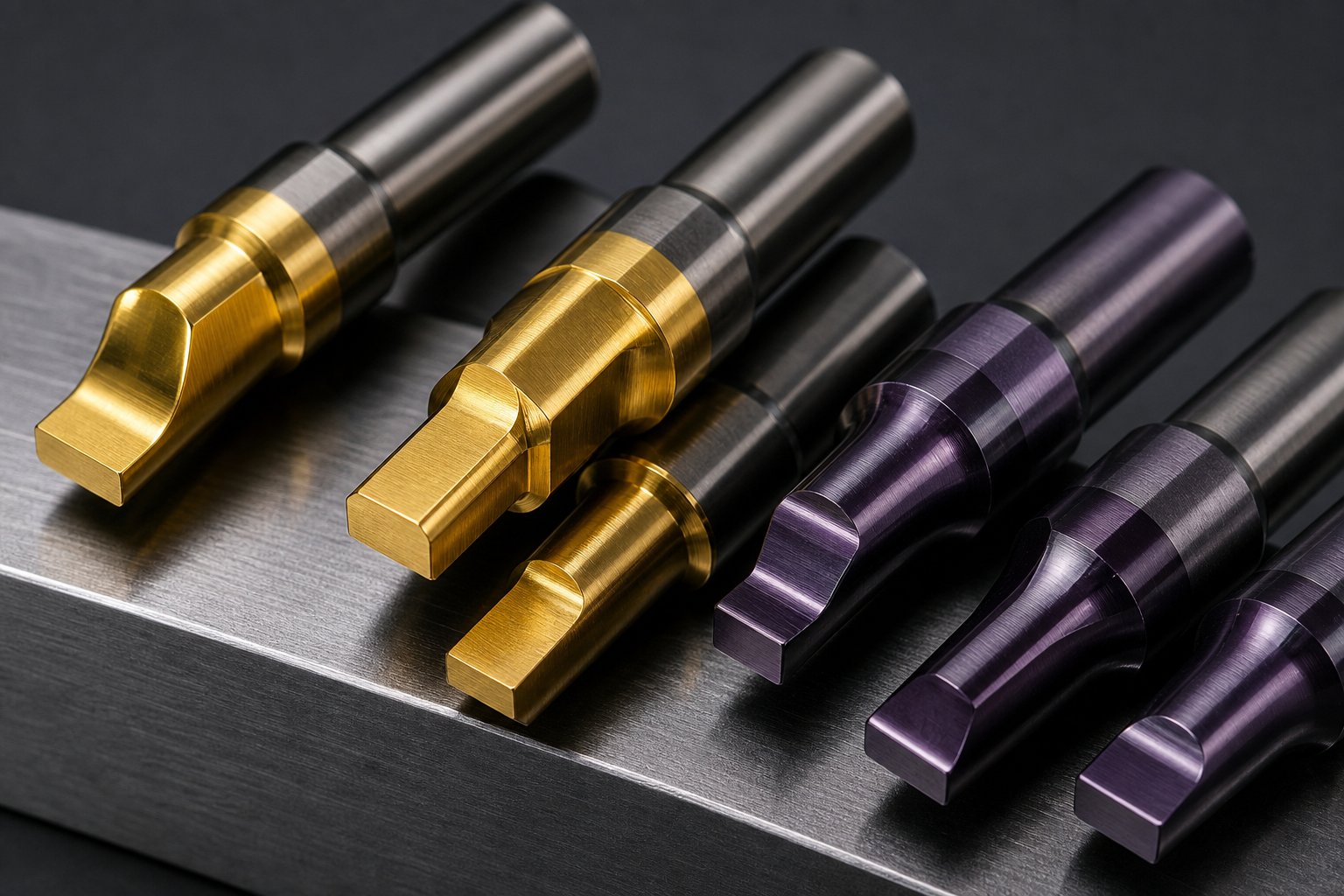
- TiN (Titanium Nitride) - The standard all-purpose coating with a characteristic gold color. Micro-hardness of approximately 2200 HV, maximum coating thickness of 10 micrometers. Best suited for general metal forming and plastic molding applications where moderate wear resistance is sufficient. Its higher friction coefficient (0.6 dry over steel) limits effectiveness in aggressive forming operations.
- TiCN (Titanium Carbonitride) - Steps up hardness to approximately 3400 HV with a significantly lower friction coefficient of 0.2. Maximum thickness around 6 micrometers. The enhanced toughness and abrasive wear resistance make it ideal for high-performance cutting and metal forming, particularly on stainless steel workpieces where galling is the dominant failure mode.
- TiAlN (Titanium Aluminum Nitride) - Delivers high hardness (approximately 3200 HV) with excellent oxidation resistance at elevated temperatures. Maximum thickness of 10 micrometers. Performs best in high-speed operations or semi-dry machining conditions where thermal loading is significant. Its heat resistance makes it the preferred choice when press speeds generate substantial frictional temperatures at punch surfaces.
- DLC (Diamond-Like Carbon) - The lowest friction option available, with coefficients below 0.1 and hardness reaching 4000 HV. Thickness is limited to approximately 4 micrometers in standard applications. DLC excels at preventing adhesion on non-ferrous metals and reducing stripping forces in forming operations where material wants to grip the punch on the return stroke.
- Nitriding - A thermochemical diffusion process rather than a deposited coating. Nitrogen atoms penetrate the tool steel surface, creating a hardened case without a distinct layer boundary. Best for large forming surfaces where coating adhesion could be problematic, or as a pre-treatment beneath PVD coatings for enhanced load-bearing capacity.
Matching Surface Treatments to Workpiece Materials
The workpiece material dictates which wear mechanism will dominate, and that determines the optimal coating selection.
Stainless steel presents the most aggressive galling challenge. High-strength grades like Type 301 in quarter-hard temper generate severe adhesive wear on forming and coining surfaces. Research at Penn United Technologies demonstrated that PVD chromium nitride coatings on carbide tooling extended die life from 15,000 hits between recoating to several million hits before tool failure. That's not an incremental improvement. It's a transformation of the maintenance model. TiCN is equally effective here, with its combination of high hardness and low friction coefficient directly counteracting the adhesion tendency of austenitic stainless grades.
Aluminum is notorious for material buildup on tooling surfaces. The soft metal transfers readily to uncoated punches, progressively degrading part surface quality. DLC coatings, with their extreme low friction and anti-adhesion properties, virtually eliminate this failure mode in aluminum blanking applications.
Copper and brass present a different challenge in progressive stamping copper terminals and connectors. These softer materials generate less abrasive wear but create adhesion problems at higher speeds. DLC or TiCN coatings reduce stripping forces and prevent material pickup that would otherwise require frequent polishing. Copper progressive stamping operations running at 800+ strokes per minute see particularly strong benefits from low-friction coatings, since the repeated high-speed contact amplifies any adhesion tendency.
Testing conducted at Deakin University in partnership with Ford confirmed that TiCN coatings increased die life by a factor of more than 20 compared to polished-only surfaces, while hard chrome provided a 12x improvement. The study also revealed that simply improving the base surface finish from 2.4 micrometers to a smoother preparation increased die life sevenfold before any coating was applied. Coating performance builds on surface preparation quality.
Coating Economics and Recoating Intervals
PVD and CVD represent the two primary application methods, and the choice between them matters for precision tooling. PVD (Physical Vapor Deposition) operates at significantly lower temperatures, typically below 500 degrees Celsius. This prevents the dimensional distortion and hardness loss that higher-temperature processes can introduce. For tolerance-critical die components already heat-treated to precise specifications, PVD preserves those properties intact.
CVD (Chemical Vapor Deposition) applies coatings at temperatures exceeding 1800 degrees Fahrenheit. While CVD produces excellent adhesion and uniform coverage on complex geometries, the thermal cycle can alter substrate hardness and cause dimensional changes that require regrinding. Most precision die & stamping applications favor PVD for this reason.
Recoating intervals depend on the interaction between coating type, workpiece material, press speed, and lubrication strategy. In general terms:
- Uncoated polished dies on stainless steel: repolish every 1,000 to 7,000 hits depending on surface preparation quality
- Hard chrome on stainless steel: approximately 12,000 hits between service
- PVD TiCN or CrN on stainless steel: several hundred thousand to millions of hits before recoating
- DLC on aluminum or copper: extended intervals limited primarily by coating thickness depletion rather than adhesive failure
Lubrication interacts with coating selection in ways that aren't always intuitive. A high-performance coating with minimal lubrication can outperform an uncoated die swimming in stamping oil. This opens the door to reduced lubricant usage, cleaner parts, and lower waste disposal costs. For copper progressive stamping where residual oil contamination affects downstream soldering or plating, DLC's ultra-low friction enables dry or near-dry operation that eliminates post-stamp cleaning entirely.
The economics favor coating when the cost of a single unplanned die failure, including scrap, downtime, and expedited repair, exceeds the cost of coating every wear-critical component in the tool. For most high-volume progressive dies, that math works out decisively in favor of coating. The remaining question is how to build that coating decision into the broader die development process, from initial part analysis through validated production release.
The Die Development Lifecycle From Concept to Production
Steel grade, heat treatment, and surface coatings define what a precision stamping die can endure. But the sequence of decisions and processes that transform an engineering concept into a validated production tool determines whether those material choices actually deliver their potential. A progressive die manufacturer doesn't just machine components. They orchestrate a development lifecycle where each phase locks in precision that subsequent phases depend on.
Here's the reality: design freedom is highest at the beginning of a project, when manufacturing knowledge about the specific part is lowest. Stamping simulation and virtual validation exist precisely to close that gap, making science-based knowledge available before committing to hard tooling. The lifecycle below reflects how modern progressive die & stamping programs manage that tension between freedom and knowledge.
From Part Print to Strip Layout Simulation
Every prog die project follows a structured development path. Skip a phase or rush through it, and you'll discover the cost downstream in rework, scrap, or compromised tool life. The complete lifecycle unfolds in this sequence:
- Part analysis and feasibility - Engineers evaluate the part print for manufacturability. They assess material properties, geometric complexity, tolerance requirements, and annual volume to determine whether the part is suitable for progressive die production. Critical questions get answered here: Can this bend radius be formed without cracking? Does this tolerance require carbide tooling? Will the annual volume justify the tooling investment?
- Strip layout and simulation - The strip layout defines station sequencing, pitch distance, carrier design, and material utilization. CAE simulation then validates material flow, predicts thinning or cracking risks, and optimizes forming pressures before any steel is cut. This virtual tryout identifies potential defects in a digital environment, reducing physical trial-and-error costs significantly.
- Detail design and 3D modeling - Every punch, die block, insert, stripper plate, and guide component gets modeled to exact specifications. Clearances, interference checks, and assembly sequences are verified digitally. Idle stations are reserved for future engineering changes, preventing costly die rebuilds when part revisions inevitably arrive.
- Wire EDM and CNC machining - Components are manufactured using precision machining technologies matched to their tolerance requirements. Die plates and shoes get CNC milled. Punch profiles and die openings are cut by wire EDM. Critical forming surfaces receive CNC jig grinding for final geometry.
- Assembly and spotting - Components are assembled into the die shoe, and spotting verifies that mating surfaces contact properly under load. Shut heights are set, timing is confirmed, and strip passage is checked through every station.
- Tryout and validation - The die runs sample parts on a tryout press. Dimensions are measured, springback is quantified, and adjustments are made to forming geometry. CPK analysis through continuous sampling confirms dimensional stability.
- Production release - The die is approved for full-rate production after meeting all dimensional, cosmetic, and process capability requirements. Documentation packages including maintenance SOPs and sharpening intervals are finalized.
Design-for-manufacturability thinking runs through every phase. Engineers design punch geometries that can be resharpened without complex fixturing. They specify insert construction at high-wear stations so individual components can be replaced without disassembling the entire tool. They locate guide pins and dowels for repeatable reassembly after maintenance. These decisions don't make the initial build cheaper, but they dramatically reduce the lifetime cost of operating the tool.
Precision Machining Technologies in Modern Die Building
The tolerances achievable in a finished precision stamping die are ultimately limited by the machining technologies used to create its components. Three capabilities define the current state of the art:
Wire EDM cuts hardened tool steel using a thin electrically charged wire, achieving tolerances of ±0.0001 to ±0.0003 inch with radii as small as 0.0005 inch. This process creates punch and insert geometry in progressive dies without thermal stress or mechanical force, meaning hardened components can be machined to final dimensions after heat treatment. Slow-wire cutting, a refined variant using finer wire and multiple skim passes, pushes surface finish quality below 0.2 micrometers Ra while holding positional accuracy within a single micron.
CNC jig grinding achieves positional accuracy within 0.001 mm on hole patterns and contoured surfaces. For die blocks where multiple cavity positions must relate to each other precisely, jig grinding provides the coordinate accuracy that ensures station-to-station alignment across the full length of a progressive tool.
Sinker EDM handles complex three-dimensional cavities and form punch geometries that wire EDM cannot reach. Tolerances of ±0.0002 to ±0.0005 inch enable intricate internal geometries, deep cavities, and undercuts that reduce the number of assembled components by consolidating complex shapes into single inserts.
These technologies work together. CNC milling roughs components to near-net shape quickly and economically. Wire EDM then cuts final profiles and clearances to micron-level accuracy. Jig grinding finishes critical datum surfaces. The combination means a progressive die manufacturer can hold overall die tolerances tighter than any single process could achieve alone.
Tryout Validation and Production Release Criteria
Sounds straightforward? The tryout phase is where engineering assumptions meet physical reality. A die can be machined perfectly and still produce out-of-spec parts if material springback, friction conditions, or press deflection weren't adequately predicted during simulation.
Validation follows a structured protocol:
- T0 samples - First parts off the die. Measured against print dimensions to quantify deviation from nominal. Springback on formed features is the primary concern here.
- Geometry correction - Die geometry is adjusted to compensate for observed springback. Forming punches may be reground or shimmed. Overbend angles are tuned until parts fall within tolerance after elastic recovery.
- T1 samples - Parts produced after corrections, measured to confirm that adjustments achieved the target. Multiple samples verify consistency, not just single-part accuracy.
- CPK validation - Continuous sampling over an extended run (typically 30+ consecutive parts) confirms process capability. A CPK of 1.33 or higher on critical dimensions indicates the process is stable enough for production release.
Production release isn't simply "parts are good." It means the die produces conforming parts reliably, the process window is documented, and maintenance parameters are established. Hit-count-based inspection intervals, sharpening thresholds, and component replacement criteria all get defined during this phase, creating the maintenance framework that protects die performance over its production lifetime.
Die Maintenance Strategy and Failure Mode Analysis
Production release criteria establish the maintenance framework, but keeping a precision stamping die within spec over millions of cycles requires something more than a schedule pinned to a wall. It demands a structured strategy that connects observable symptoms to root causes, ties service intervals to actual wear data, and accounts for how press dynamics influence die degradation. Surprisingly, this is where many tooling programs fall short. The die gets built to exceptional standards, then deteriorates under a reactive maintenance culture that only responds after scrap rates spike.
A better approach treats maintenance as an engineering discipline, not a janitorial task. That means understanding why components fail, when to intervene, and how your press type accelerates or mitigates specific wear mechanisms.
Common Failure Modes and Root Cause Identification
When a progressive die starts producing reject parts, the visible symptom rarely tells the whole story. A burr on a stamped edge looks like a dull punch, but the actual cause might be thermal expansion changing punch-to-die clearance, a loose retainer allowing lateral movement, or inadequate lubrication creating adhesive buildup. MetalForming Magazine emphasizes that a complete failure analysis requires collecting samples, compiling background data, and examining fracture surfaces before jumping to conclusions.
Consider the distinction between manufacturing errors and service-condition failures. A punch that chips because a specified corner radius was left sharp during grinding is a manufacturing error. A carbide insert that cracks because chlorinated lubricant attacked its cobalt binder is a service-condition failure. Both produce the same symptom, chipping, but demand entirely different corrective actions.
Design errors also contribute significantly. Thick sections adjacent to thin sections, abrupt cross-sectional changes, and improperly sized fillet radii all create stress concentrators that eventually nucleate cracks under cyclic loading. These aren't maintenance problems. They're engineering problems that maintenance alone cannot resolve.
The following table maps the most common failure modes in precision progressive dies to their root causes and appropriate corrective responses:
| Failure Mode | Observable Symptom | Root Cause | Corrective Action |
|---|---|---|---|
| Punch chipping | Irregular edge fragments missing from punch tip; inconsistent burr pattern | Material fatigue from cyclic loading; insufficient toughness for application; sharp internal corners creating stress risers | Evaluate steel grade (consider S7 for toughness); increase fillet radii; verify heat treatment achieved target hardness-toughness balance |
| Galling | Material buildup on punch or die surfaces; scratches and score marks on stamped parts | Inadequate lubrication; insufficient clearance for material type; poor surface finish on tooling; high-friction workpiece material (stainless, aluminum) | Apply PVD coating (TiCN or DLC); improve surface finish; verify clearance per material thickness; upgrade lubrication delivery |
| Die cracking | Visible fracture lines in die block or insert; sudden catastrophic failure | Thermal cycling stress; improper heat treatment (insufficient tempering); design features creating stress concentration; overloading from slug stacking | Review heat treatment records; add tempering cycles; redesign stress concentrators; verify tonnage capacity and slug evacuation |
| Excessive burr formation | Progressively increasing burr height on stamped edges | Worn cutting edges (normal wear); punch-to-die clearance drift from component looseness; thermal expansion altering clearance | Sharpen per documented threshold; verify retainer security and clearance; check for thermal management issues at press speed |
| Timing misalignment | Elongated pilot holes; progressive dimensional drift between stations; misfeed events | Feed-roll-lift timing error; worn or bent pilots; press parallelism loss; strip lifter malfunction | Recalibrate feed timing; inspect pilots for wear (0.0005-0.001 in. clearance tolerance); verify press gibs and parallelism; service lifter rails |
| Slug pulling | Slugs pulled back into die face; witness marks on strip underside | Increased punch-to-die clearance allowing vacuum effect; oil film acting as adhesive; worn slug retention features | Restore proper clearance; add slug retention grooves or modify punch geometry; adjust lubrication volume at piercing stations |
The critical insight from any failure analysis: you'll notice that most root causes trace back to decisions made during design and build, not just operational wear. Industry data confirms that tool design, material selection, and heat treatment deserve equal investigative weight alongside service conditions when diagnosing recurring failures.
Preventive Maintenance Scheduling by Hit Count
Calendar-based maintenance schedules miss the point for stamping dies. A tool running two shifts at 600 strokes per minute accumulates wear fundamentally differently than one running single-shift at 200 SPM, even over the same calendar week. Effective preventive maintenance ties inspection triggers to actual production counts.
The framework works in tiers:
- Per-shift checks (every run start) - Visual inspection for trapped slugs, debris, and obvious damage. Verify lubricant delivery is reaching intended points. Confirm feed pitch and strip tracking. Flag any burr-related quality changes immediately. These checks take minutes but catch the conditions that escalate into hours of unplanned downtime.
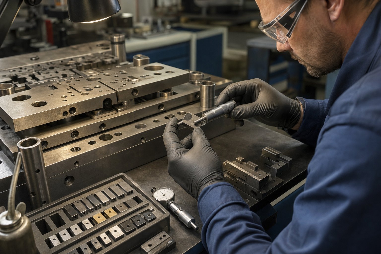
- Stroke-count-based inspection (typically every 50,000-250,000 hits) - The interval depends on workpiece material abrasiveness, press speed, and historical wear data for the specific tool. At this trigger, measure cutting-edge condition, check clearances with feeler gauges, inspect pilots for one-sided wear, and verify spring free-length hasn't degraded beyond 10%. Industry guidance recommends triggering punch regrind review when edge wear exceeds 0.1 mm.
- Sharpening threshold - Rather than sharpening on a fixed schedule, measure actual burr height on production parts. When burr exceeds the part specification (often 0.05-0.10 mm for precision applications), schedule sharpening. Document the hit count at each sharpening event. Over time, this builds a predictive model for each die's actual wear rate.
- Component replacement criteria - Springs get replaced when free length drops 10% or cracking appears. Pilots get replaced when clearance to pilot holes exceeds design intent. Guide bushings get replaced when scoring is visible or when measured clearance to guide pins exceeds documented limits. These aren't judgment calls. They're measurable thresholds.
Documentation ties the entire system together. Every maintenance event should record: hit count at service, defects found, actions taken, components replaced, and first-off quality result after the die returns to production. Progressive die stampings suppliers serving automotive dies programs understand this discipline instinctively, because IATF 16949 quality systems demand traceable maintenance records as a condition of supplier approval.
Without hit-count data, you're guessing. With it, you can predict when the next service is needed, budget for replacement components in advance, and identify the specific stations that drive disproportionate maintenance cost.
How Press Type Influences Die Wear Patterns
The press isn't just a power source. It's the dynamic environment your die lives in, and its characteristics directly shape which failure modes appear first and how quickly they progress. Three press architectures dominate precision stamping production, and each creates a distinct wear signature.
Mechanical presses deliver force through a crank mechanism, meaning velocity and available tonnage vary continuously through the stroke. Peak velocity occurs at mid-stroke, and tonnage is maximum only at bottom dead center. This creates very short cycle times ideal for high-volume blanking and piercing, but the fixed stroke profile means forming operations experience different strain rates depending on where in the stroke they occur. Die wear patterns on mechanical presses tend toward impact-related failures: punch chipping at engagement, snap-through shock during blanking, and fatigue cracking from repeated dynamic loading. HVAC progressive stamping operations producing heat exchanger fins at 1,000+ SPM on mechanical presses see accelerated wear at piercing stations simply due to the cumulative impact energy at those cycle rates.
Servo presses use programmable servo motors to control ram speed, position, and force independently throughout the stroke. You can slow the ram during material engagement to reduce impact shock, apply full tonnage gradually during forming, and retract at maximum speed to minimize cycle time. The result: significantly reduced die wear. The die experiences lower peak forces, reduced thermal cycling, and less snap-through shock. Components that chip after 200,000 hits on a mechanical press may run 500,000 or more on a servo press forming the same part. Maintenance intervals stretch proportionally.
Hydraulic presses provide full tonnage at any point in the stroke with adjustable speed, making them excellent for deep drawing and complex forming operations. However, their slower cycle times limit throughput for high-volume progressive die work. Die wear patterns on hydraulic presses favor sustained-contact mechanisms: galling from prolonged tooling-workpiece contact at forming stations, thermal effects from slower heat dissipation, and surface degradation from extended dwell time under load. Automotive dies for deep-drawn structural components often run on hydraulic presses precisely because the controlled speed prevents the cracking and tearing that high-velocity mechanical strokes would produce in deep draws.
The practical takeaway: your maintenance schedule should account for press type, not just hit count. A die running on a servo press at 400 SPM may need less frequent service than the same die running on a mechanical press at 300 SPM, because the servo's controlled engagement reduces cumulative damage per stroke. Conversely, a hydraulic press forming operation may need more frequent surface inspection for galling despite running at lower speeds, because each stroke sustains contact longer.
Understanding these failure mechanisms and maintenance strategies keeps a precision die producing conforming parts. But the specifications driving those tolerances, the clearances that define acceptable burr, and the production volumes that justify tight maintenance discipline all originate from the application itself. What the stamped part does in its final assembly determines everything the die must deliver.
Industry Applications and Die Specification Decisions
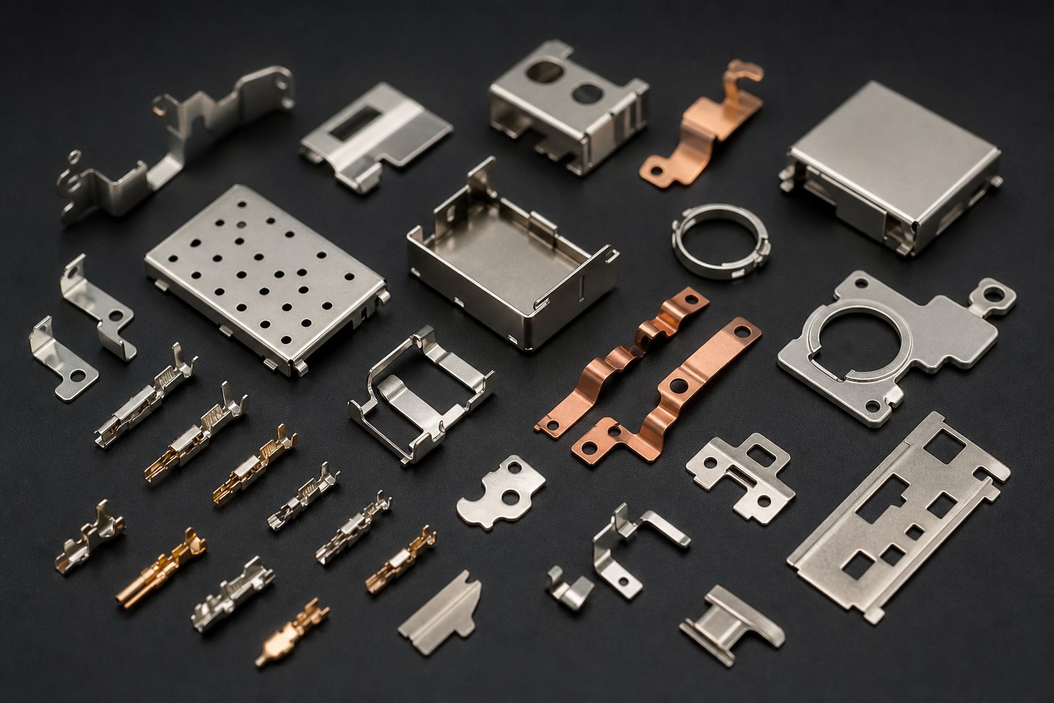
Tolerance thresholds, maintenance intervals, and coating selections don't exist in a vacuum. They're driven by what the finished part actually does once it leaves the press. A copper terminal inside an automotive connector harness operates under different mechanical, electrical, and thermal constraints than an aluminum fin in a heat exchanger. Those end-use requirements flow backward through the engineering chain, dictating everything from steel grade to station count in the progressive die that produces the part.
Understanding this relationship helps engineering teams specify tooling that matches their application rather than over-engineering for margin they don't need or, worse, under-specifying for tolerances they absolutely do.
Automotive and Electrical Connector Applications
Automotive components progressive stamping represents one of the most demanding sectors for precision tooling. Tier 1 suppliers serving OEMs need dies that produce millions of identical parts annually while holding tolerances that ensure reliable electrical contact and mechanical retention.
Imagine a multi-pin connector housing with spring contacts spaced 1.27 mm apart. Each contact must maintain a specific normal force against the mating pin, and that force depends on material thickness, bend geometry, and dimensional consistency across every single part. A deviation of 0.05 mm on a contact arm length changes spring force enough to cause intermittent connections in service. That's the tolerance reality driving OEM progressive stamping specifications.
Progressive dies for electric and hybrid vehicles now produce high-precision motor laminations, bus bars, and connectors at production speeds up to 1,400 strokes per minute. These applications combine tight tolerances with aggressive annual volumes, often exceeding 10 million pieces. Die specifications for this segment typically call for carbide inserts at critical piercing stations, TiCN or DLC coatings on forming punches, and servo press compatibility to reduce impact wear at those cycle rates.
The key specification drivers for automotive electrical applications:
- Material - Phosphor bronze, beryllium copper, or pre-plated copper alloys ranging from 0.1 to 0.8 mm thickness
- Tolerances - Typically ±0.02 to ±0.05 mm on critical contact dimensions; positional accuracy within ±0.03 mm between features
- Volume - Multi-million annual quantities justifying carbide tooling and full coating programs
- Die complexity - 20 to 40+ stations incorporating in-die assembly, selective over-molding inserts, or in-die tapping for integrated components
HVAC and Copper Stamping at High Speed
HVAC progressive metal stamping occupies the opposite end of the complexity spectrum but pushes speed limits harder than almost any other application. Heat exchanger fins are geometrically simple, thin aluminum parts produced at extraordinary rates, often 1,200 to 1,500 strokes per minute on dedicated high-speed presses.
At those speeds, die wear accumulates fast. A fin die running 1,400 SPM across three shifts produces over 2 million hits per day. Even with aluminum's relatively low abrasiveness, that cumulative contact degrades tooling surfaces rapidly without proper coating and lubrication strategy. Tooling specifications for HVAC progressive stamping prioritize:
- Material - Thin aluminum strip (0.08 to 0.15 mm) requiring extremely sharp cutting edges and minimal burr
- Speed - 1,000 to 1,500+ SPM demanding lightweight die components, robust pilot registration, and anti-adhesion coatings (DLC preferred)
- Die life management - Frequent sharpening cycles due to extreme hit counts; modular insert construction for rapid station service without full die removal from press
- Strip width - Wide coil stock (up to 500 mm or more) feeding multiple rows simultaneously for maximum output
Copper progressive stamping for electrical terminals and bus bars presents different demands. Copper work-hardens during forming, increasing press loads as production runs progress. Die specifications must account for higher tonnage requirements at forming stations and the adhesion tendency of copper against uncoated tool steel. OEM tolerance requirements for these parts routinely fall within ±0.001 to ±0.005 inch, with surface finish constraints driven by downstream plating or soldering processes.
Medical and Electronics Precision Requirements
Medical device components and consumer electronics shielding push precision dies toward their tightest tolerance capability. A stamped EMI shield for a smartphone must fit within a cavity measured in fractions of a millimeter, with flatness requirements that prevent gaps allowing electromagnetic leakage. Medical contact springs, surgical instrument components, and implantable device housings demand not only dimensional precision but complete traceability and process validation.
What distinguishes these applications from automotive work isn't necessarily tighter tolerances. It's the combination of tight tolerances with exotic materials and lower volumes that change the economic equation:
- Electronics shielding - Thin stainless steel or nickel silver (0.1 to 0.3 mm); complex bend geometries requiring multiple forming stations; flatness within 0.05 mm across shield surfaces; moderate volumes (500K to 5M annually)
- Medical devices - Titanium, surgical stainless, or specialty alloys demanding specific material certifications; tolerances of ±0.01 to ±0.025 mm; full lot traceability with CPK documentation per production run; lower volumes (50K to 500K) that must still justify progressive die investment
- Micro-connectors - Pitch distances below 0.5 mm between contacts; feature sizes approaching the limits of wire EDM capability; strip widths under 20 mm with single-row progression; carbide tooling mandatory for dimensional stability across production life
For medical and electronics applications, die specification decisions shift toward quality assurance infrastructure as much as mechanical capability. The die must not only produce conforming parts but must do so within a validated, documented process that satisfies regulatory requirements. That validation rigor ties directly back to how the die was developed, who built it, and what quality systems governed its manufacture, questions that lead naturally to how engineering teams evaluate and select their tooling partner.
Selecting a Precision Stamping Die Partner for Critical Parts
Regulatory traceability, validated processes, and documented capability don't originate with the stamped part. They originate with the organization that designed and built the die. For engineering teams specifying tooling for tolerance-critical applications, selecting the right progressive die manufacturer is less about finding the lowest quote and more about identifying a partner whose technical infrastructure matches the demands of the application. A supplier equipped for general bracket stamping operates in a fundamentally different engineering environment than one built around micro-connectors, thin-gauge copper terminals, or medical device components requiring ±0.01 mm repeatability.
So how do you separate progressive die manufacturers genuinely equipped for precision-grade work from those marketing beyond their capability? The answer lies in evaluating specific technical benchmarks, verified quality systems, and demonstrated process discipline.
Technical Capability Benchmarks for Die Suppliers
When you're sourcing a precision stamping die for small, complex parts at high volume, the supplier's equipment list tells you more than their sales presentation. You need to look beyond general CNC capacity and examine the specific machining technologies that enable micron-level accuracy.
Here's a practical evaluation framework. A supplier suited for tolerance-critical progressive die work should demonstrate:
- Wire EDM capability with ±0.001 mm or better accuracy - This is non-negotiable for punch and die insert profiles where clearances are measured in single-digit microns. Ask whether they run slow-wire with multiple skim passes for final surfaces.
- CNC jig grinding for coordinate accuracy - Critical for maintaining station-to-station positional relationships across long progressive die shoes. Without jig grinding, cumulative positional errors across 20+ stations become unavoidable.
- In-house heat treatment or verified subcontractor control - Heat treatment directly determines whether tool steel reaches its performance potential. Suppliers who outsource this process without documented parameter verification introduce an uncontrolled variable.
- Stamping simulation software (AutoForm, DYNAFORM, or equivalent) - Simulation-driven development reduces tryout iterations and predicts springback, thinning, and material flow before hard tooling is cut. Suppliers relying solely on experience-based trial-and-error carry higher risk for complex geometries.
- Tryout press availability matching production conditions - A supplier should validate dies on a press that replicates your production environment: matching tonnage, stroke rate, and feed system type. Validating a 400 SPM progressive die on a 60 SPM tryout press leaves speed-dependent failure modes undiscovered.
- In-house surface treatment or established coating partnerships - PVD coating decisions should be integrated into the design phase, not treated as an afterthought. Suppliers who coordinate coating selection with workpiece material and press speed deliver longer-lasting tooling.
- Metrology equipment calibrated to measure what they build - CMM capability, optical measurement systems, and surface profilometry appropriate for the tolerance range they claim to achieve.
A general stamping house might own a wire EDM machine. A precision die and stamping specialist runs it within a process discipline that includes documented programs, verified offsets, and measured output validated against CAD nominal. The equipment matters less than the system governing how it's used.
Quality Standards and Certification Requirements
Certifications serve as externally audited evidence that a supplier operates within a structured quality management system. For precision die applications, two certifications carry the most weight.
ISO 9001:2015 establishes the baseline. It confirms that documented processes exist for design control, calibration, internal auditing, corrective action, and supplier management. Any reputable precision die & stamping supplier should hold this as a minimum. It signals process discipline and traceability, though it doesn't mandate the automotive-specific rigor that high-volume production programs demand.
IATF 16949:2016 builds on ISO 9001 with significantly stricter requirements tailored to automotive supply chain production. It mandates APQP (Advanced Product Quality Planning), PPAP (Production Part Approval Process), FMEA, SPC, and MSA as core quality tools. For teams sourcing automotive dies or any safety-critical stamped component, IATF 16949 certification isn't a preference. It's a prerequisite. The standard requires process capability studies targeting Cpk of 1.33 or higher on critical dimensions, pushing suppliers toward the statistical rigor that prevents dimensional drift across long production runs.
Beyond the certificate itself, verify the scope. A supplier might hold IATF 16949 for assembly operations but not for die manufacturing. The certification scope should explicitly cover tool and die design, build, and validation at the site where your tooling will be produced. Request the actual certificate and confirm it through the IATF oversight database rather than relying on a logo displayed on a website.
Evaluating Tooling Partners for Tolerance-Critical Production
Technical capability and certifications establish whether a supplier can do the work. The remaining question is whether they're the right fit for your specific production reality.
Progressive die manufacturers serving high-volume, tight-tolerance applications share characteristics that distinguish them from general tooling houses:
- Application-specific experience - A supplier who has built dies for your material type, part size range, and industry understands the failure modes and design accommodations specific to your application. Ask for case studies or reference parts in similar material and tolerance bands.
- Design-for-maintenance philosophy - Precision tooling built for multi-million-hit production must be serviceable. Evaluate whether the supplier designs with modular inserts, accessible sharpening surfaces, and documented maintenance procedures as standard practice.
- Engineering collaboration during development - The best tooling partners engage during part design, not after the print is frozen. Design for manufacturability input from the die builder can reduce station count, improve material utilization, and eliminate tolerance stacking before tooling investment begins.
- Validated process from simulation through production release - A complete development lifecycle with documented validation gates (simulation, T0 tryout, CPK confirmation) reduces risk compared to build-and-adjust approaches.
- Responsive service and modification capability - Production parts evolve. Engineering changes arrive. A supplier with in-house machining depth can execute modifications quickly without restarting the tooling program from scratch.
For engineering teams evaluating partners that specialize in precision-grade progressive dies for high-volume, tight-tolerance applications, YICHEN's Precision Stamping Die program serves as a resource worth examining. YICHEN focuses specifically on small, high-accuracy parts built for repeatable mass production, the segment where die precision directly determines whether finished components meet functional requirements in their final assemblies.
The supplier selection decision ultimately reflects a risk calculation. The cost difference between a precision die and stamping specialist and a general-purpose shop is typically modest relative to total program cost. But the cost of a die that can't hold tolerance at production speed, or one that requires monthly intervention because wear management wasn't designed in from the start, compounds across every hit for the life of the tool. Invest evaluation time upfront, and the tooling pays for itself through years of stable, predictable production.
Frequently Asked Questions About Precision Stamping Dies
1. What tolerance can a precision stamping die hold?
A precision stamping die typically holds dimensional tolerances within ±0.0002 inch (±0.005 mm) or tighter across millions of press cycles. This level of accuracy is achieved through controlled punch-to-die clearances of 5-10% material thickness per side, micrometer-level positional accuracy between stations, and pilot registration systems that correct feeding inaccuracies at every station. Maintaining these tolerances requires specific tool steel grades hardened to HRC 58-64, wire EDM machining with ±0.0001 inch capability, and validated maintenance schedules tied to hit-count data rather than calendar intervals.
2. What is the difference between a progressive die and a compound die?
A progressive die performs sequential operations across multiple stations as a metal strip advances one pitch distance per press stroke, producing one finished part per cycle at speeds up to 1,500+ SPM. It handles complex geometries by distributing cuts, bends, and forms across dedicated stations. A compound die executes multiple operations simultaneously at a single station in one press stroke, making it ideal for flat, symmetrical parts requiring tight concentricity between features. Progressive dies suit high-volume complex parts (100,000+ annually), while compound dies work best for moderate-volume flat parts where feature-to-feature concentricity is critical.
3. Which tool steel is best for stamping die punches?
The best tool steel depends on the dominant failure mechanism in your application. D2 (SKD11) excels when abrasive wear limits die life, offering high edge retention at 58-60 HRC. M2 (SKH51) resists both wear and compressive deformation at 60-65 HRC, ideal for punches under heavy loading. S7 provides maximum toughness at 56-58 HRC for high-impact stations where chipping or cracking occurs. A2 (SKD12) delivers balanced performance when multiple failure modes compete. Tungsten carbide inserts justify their 3-5x cost premium at ultra-high-volume stations where tool steel maintenance intervals become production bottlenecks.
4. How often should a precision stamping die be maintained?
Maintenance frequency should be tied to actual hit counts rather than calendar schedules. Per-shift visual checks catch trapped slugs and lubrication issues. Stroke-count-based inspections every 50,000 to 250,000 hits measure cutting-edge condition, clearances, pilot wear, and spring free-length. Sharpening triggers when burr height exceeds part specifications, typically 0.05-0.10 mm for precision work. Springs require replacement when free length drops 10%. Press type also affects intervals: dies on servo presses may need less frequent service than identical tools on mechanical presses, since controlled engagement reduces cumulative impact damage per stroke.
5. What coatings extend precision stamping die life?
PVD coatings like TiCN (3400 HV hardness, 0.2 friction coefficient) and DLC (4000 HV, friction below 0.1) deliver the most significant die life improvements for precision applications. TiCN excels against stainless steel galling, extending die life over 20x compared to polished-only surfaces. DLC prevents aluminum and copper adhesion, enabling near-dry stamping that eliminates post-cleaning. TiAlN suits high-speed operations generating thermal loading. PVD application below 500 degrees Celsius preserves substrate hardness and dimensional accuracy, making it preferred over CVD for tolerance-critical components. Coating selection should match the specific workpiece material and dominant wear mechanism.


