


What Is an Auto Stamping Die and Why It Matters
Imagine a flat sheet of steel entering a machine and emerging seconds later as a perfectly shaped fender, door panel, or structural cross member. That transformation happens inside a single piece of precision tooling, and when it fails, entire production timelines collapse. Understanding what this tooling actually is, and why its engineering matters so deeply, is the first step toward preventing costly failures downstream.
Definition and Core Function of an Auto Stamping Die
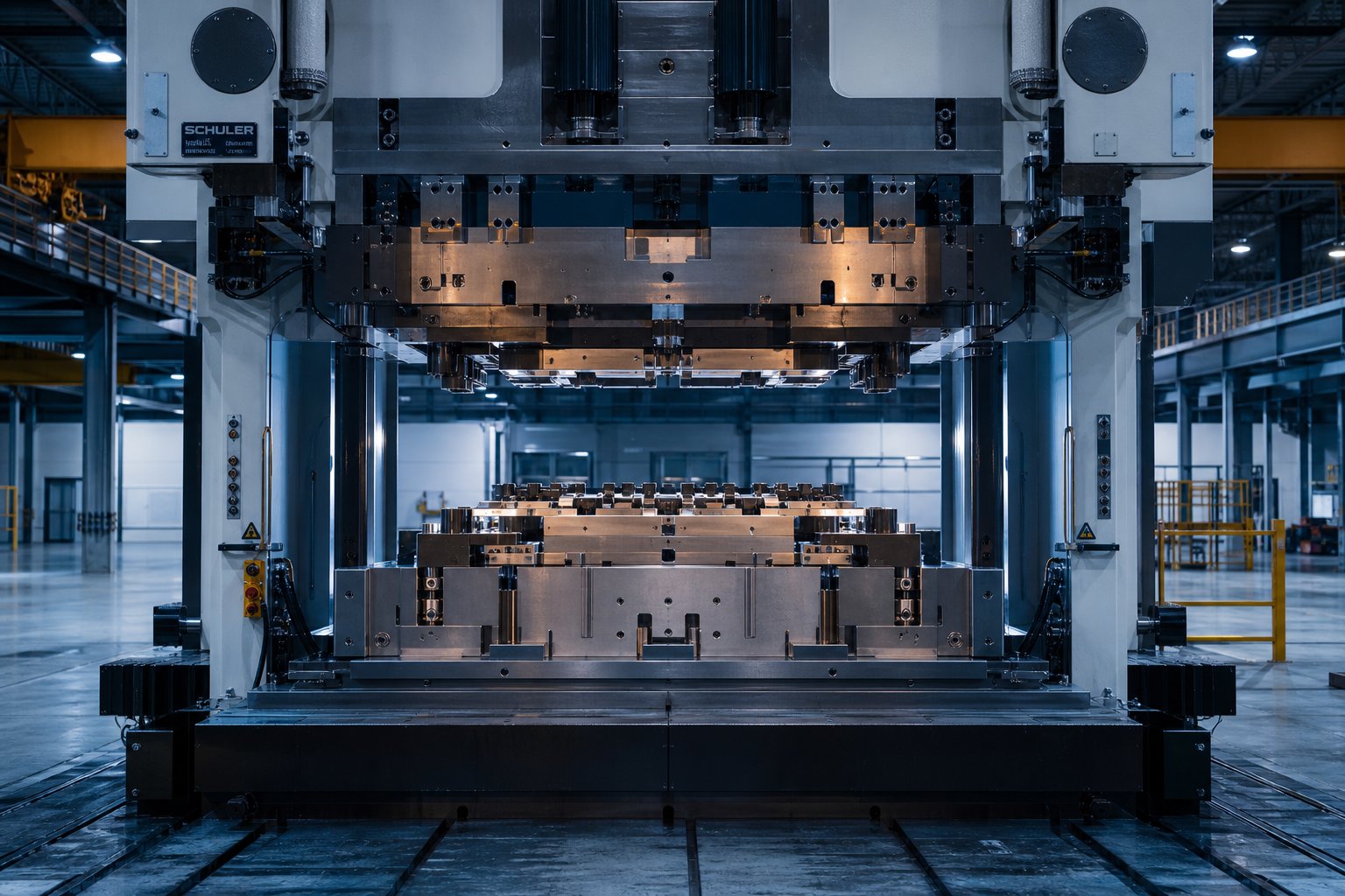
An auto stamping die is a matched set of upper and lower tool steel components, mounted in a press, that converts flat sheet metal into three-dimensional automotive parts through controlled cutting, bending, and forming in a single press stroke or series of strokes.
At its core, the die works like a highly engineered mold for metal. The upper half (typically carrying the punch) descends into the lower half (the die block), and the sheet metal caught between them is forced to conform to the cavity geometry. A blank holder clamps the material edges to control how metal flows during deformation, preventing wrinkles or tears. Guide pins and bushings align upper and lower halves within tolerances as tight as 0.0001 inches, while die springs and nitrogen cylinders provide the pressure needed to hold material in place throughout the stroke.
Stamping is a cold-forming operation, meaning no external heat is applied intentionally. Yet friction between tool steel and sheet metal generates significant thermal energy, and managing that heat is one of many variables that separates a die that runs millions of cycles from one that chips on its first tryout hit.
Why Auto Stamping Dies Matter in Vehicle Production
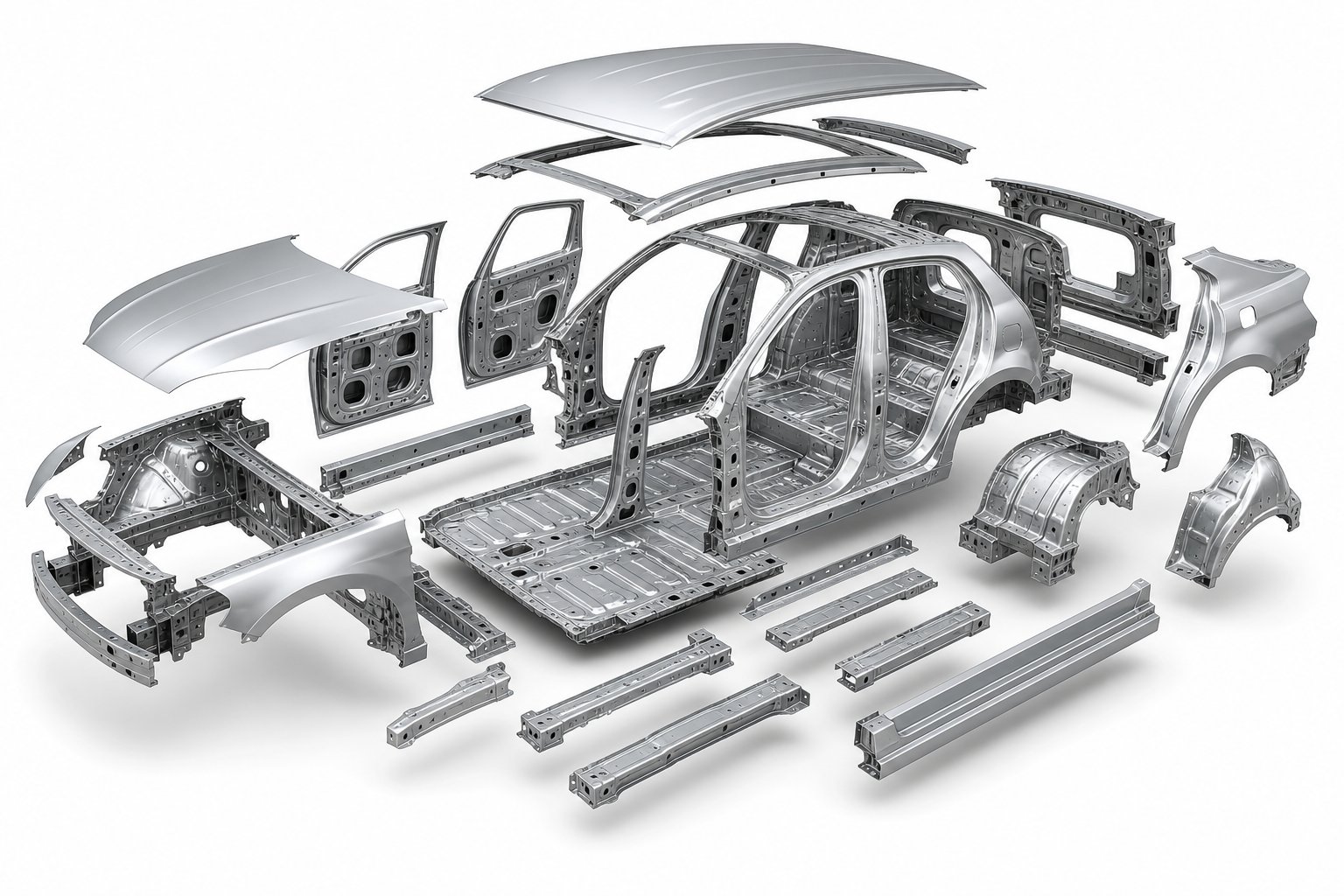
Scale tells the story. A typical vehicle body requires 250 to 300 stamped sheet-metal parts just for the body-in-white structure alone. Add chassis brackets, interior reinforcements, and structural members, and the count climbs further. Each of those parts needs its own dedicated die or station within a progressive tool. That means a single vehicle program can demand hundreds of individual stamping dies, each one engineered, built, tried out, and validated before the first production vehicle rolls off the line.
This is why die engineering is both a critical cost driver and a quality gatekeeper. A poorly designed automotive stamping die does not just produce bad parts. It stalls launch timelines, inflates tryout budgets, and introduces dimensional variation that cascades through body assembly, paint fit, and final vehicle quality. Getting the die right before production starts is not a luxury. It is a prerequisite for competitive manufacturing.
This article covers the full lifecycle of automotive stamping dies, from type selection and material strategy through simulation, tryout, maintenance, and partner evaluation. It is written as a practitioner's reference, bridging the gap between academic theory and the oversimplified overviews that dominate search results. Whether you are specifying a new progressive tool for a bracket program or troubleshooting springback on an AHSS structural panel, the sections ahead provide the engineering context you need to make better decisions at every stage.
The diversity of stamped parts on a modern vehicle, from tiny clips to full body sides, demands equally diverse die types. Each configuration carries distinct tradeoffs in cost, complexity, and production capability.
Types of Automotive Stamping Dies Compared
Choosing the wrong die type for a given part is one of the fastest paths to pre-production failure. It is not just about whether a die can form the geometry. It is about whether the tooling investment, cycle time, and material behavior align with the program's volume and quality targets. Here is how the main types of stamping dies break down in an automotive context, and when each one earns its place on the shop floor.
Progressive Dies for High-Volume Repetitive Parts
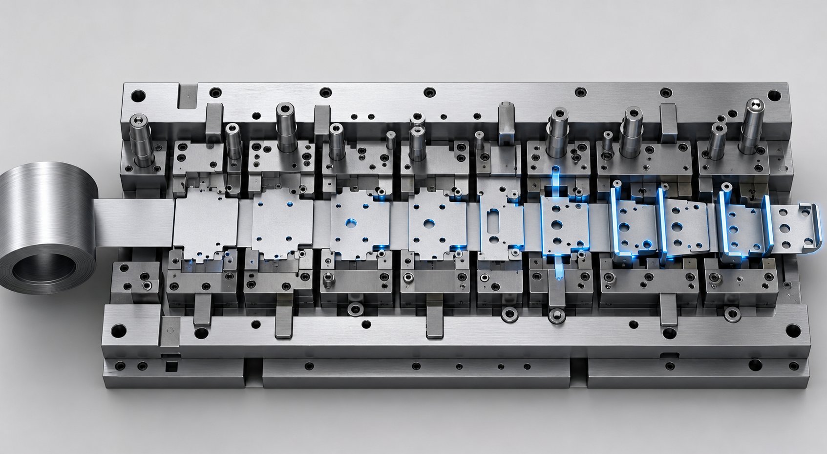
A progressive stamping die feeds a continuous coil of sheet metal through a series of stations, each performing a distinct operation: piercing, bending, coining, or trimming. The workpiece stays attached to the carrier strip throughout the process and is separated only at the final station. This keeps cycle times extremely low, often producing finished parts at 30 to 60 strokes per minute or higher.
You will find progressive dies wherever an automotive program demands high volumes of relatively small, geometrically complex parts. Think mounting brackets, electrical connectors, seat frame clips, and structural reinforcement plates. Because all operations happen in a single press pass, labor costs stay minimal and repeatability stays tight. The tradeoff? Tooling is expensive to build, lead times run longer, and deep draws are difficult since the strip constrains how far the material can flow.
Transfer Dies for Large Structural Components
The transfer die stamping process takes a fundamentally different approach. Instead of keeping the part on a strip, the blank is separated from the coil at the very first station. Mechanical fingers or automated conveyance systems then move each individual blank through successive forming stations inside a single large press.
This separation is what makes transfer dies ideal for large structural components like door inners, floor pans, and body sides. Without a carrier strip restricting material flow, engineers can achieve deep draws and complex three-dimensional shapes that a progressive tool simply cannot deliver. Transfer setups also handle intricate features such as ribs, flanges, and threaded bosses across multiple forming stages. The downside is slower cycle rates and higher sensitivity to blank positioning accuracy.
Compound and Combination Dies for Precision Work
When you need a flat, dimensionally precise part produced at high speed, compound dies deliver. These tools perform multiple cutting and forming operations simultaneously in a single press stroke. Washers, shims, backing plates, and simple brackets are typical outputs. Because every feature is created at once, concentricity and flatness tend to be superior to what a progressive tool achieves on similar geometries.
Combination dies extend this concept by merging cutting and non-cutting operations, such as blanking and drawing, into one stroke. They fill a niche for medium-volume parts where progressive tooling would be overkill but single-operation dies would require too many secondary steps.
Tandem Press Lines for Class-A Panels
Hoods, fenders, roofs, and door outers demand surface quality that tolerates zero visible imperfections after paint. These Class-A panels are typically formed on tandem press lines: a sequence of individual presses arranged in series, each performing one operation on a discrete blank. Automated crossbar transfer systems, like the Gudel roboBeam setups used by major OEMs, move parts from press to press without intermediate orientation stations. Cycle rates reach 12 to 15 strokes per minute for both steel and aluminum panels.
Tandem lines offer maximum flexibility because each press operates independently. Die changes at one station do not force redesigns at others, and tonnage can be varied per station. The leadoff press typically runs at higher capacity since the initial draw demands the most energy. This configuration handles blanks up to 4,160 mm wide and material thicknesses from 0.4 mm steel to 4 mm aluminum.
Structured Comparison of Die Types
Selecting among these sheet metal stamping dies requires weighing several factors simultaneously. The table below consolidates the key decision criteria into a single reference:
| Die Type | Production Volume | Part Complexity | Tooling Cost | Typical Lead Time | Design Change Flexibility |
|---|---|---|---|---|---|
| Progressive Die | High (100K+ annually) | Moderate to high (no deep draws) | High | 12-20 weeks | Low (changes affect multiple stations) |
| Transfer Die | Medium to high | High (deep draws, large geometry) | High | 16-24 weeks | Moderate (individual stations can be modified) |
| Compound Die | Medium to high | Low to moderate (flat parts) | Low to medium | 6-12 weeks | Moderate (single tool, simpler rebuild) |
| Combination Die | Medium | Moderate (cut + form in one stroke) | Medium | 8-14 weeks | Moderate |
| Tandem Press Line | High (Class-A panels) | High (surface-critical, large blanks) | Very high (multi-press investment) | 20-30+ weeks | High (independent stations) |
No single die type dominates across every criterion. A bracket program running 500,000 parts per year belongs in a progressive tool. A body side panel with deep draw requirements and Class-A surface demands belongs on a transfer press or tandem line. Getting this match wrong means over-investing in tooling that cannot deliver the required geometry, or under-investing in tooling that cannot sustain the required volume.
Yet even a perfectly selected die type will fail prematurely if the tool steel behind it cannot handle the material being stamped. Advanced high-strength steels and aluminum alloys punish tooling in ways mild steel never did, making material selection and surface engineering the next critical variable in die longevity.
Die Materials and Surface Treatments for Performance
A die type matched perfectly to a part's geometry can still crater before production launch if the tool steel cannot survive the material it stamps. This is where stamping die material selection separates tooling that endures millions of cycles from tooling that chips on its first high-strength steel blank. The choice is never as simple as picking the hardest grade available. Every tool steel for stamping dies represents a tradeoff between wear resistance and toughness, and the right balance depends on what the die actually does during each press stroke.
Tool Steel Grades and Their Performance Tradeoffs
Imagine a blanking punch shearing through 1.2 mm DP780 steel at 40 strokes per minute. That edge endures abrasive contact thousands of times per hour. Compare that with a forming die radius guiding the same material into a deep draw. The punch needs maximum wear resistance. The forming radius needs toughness to absorb cyclic impact loads without cracking. Same part, same press, completely different material demands on the tooling.
D2 tool steel (11-13% chromium, 1.4-1.6% carbon) sits at the wear-resistance end of the spectrum. Its abundant chromium carbides resist abrasive edge wear brilliantly, making it the default choice for blanking and piercing operations in steel stamping dies. Heat treated to 58-62 HRC, D2 can deliver two to three times the edge life of lower-alloy alternatives when processing abrasive sheet materials. The penalty is brittleness: D2 dies fail by chipping or cracking rather than gradually wearing, which makes them poor candidates for impact-heavy forming stations.
A2 tool steel (5% chromium, air-hardening) occupies the balanced middle ground. It sacrifices roughly 40-50% of D2's wear life but gains significantly better toughness and dimensional stability during heat treatment. Forming dies, drawing dies, and progressive die bodies with complex geometries benefit from A2's ability to absorb repeated shock loads without catastrophic fracture.
S7 tool steel pushes even further toward impact resistance, serving deep-draw operations and stations subjected to severe shock loading. DC53, a modified D2 variant, bridges the gap between D2-level abrasion resistance and improved toughness for applications where conventional D2 cracks prematurely.
Powder metallurgy (PM) tool steels represent the top tier. The PM production process atomizes molten alloy into fine powder and consolidates it through hot isostatic pressing, yielding a microstructure with small, evenly distributed carbides rather than the large carbide networks found in conventionally cast steels. The result is a material that delivers both high wear resistance and high toughness simultaneously. A case study documented by AHSS Insights showed that switching from conventional D2 to a PM tool steel restored die life from 5,000-7,000 cycles back to 40,000-50,000 cycles when forming a 580 MPa ferrite-bainite grade, without introducing galling or deformation problems.
Carbide Inserts and Their Role in High-Wear Zones
When even PM steels cannot sustain acceptable edge life, tungsten carbide inserts step in. These inserts are not full die components. They are strategically placed at trim edges, piercing stations, and high-contact radii where sliding contact and abrasive wear concentrate most intensely. Carbide stamping dies, or more precisely dies equipped with carbide inserts at critical wear zones, become essential when trimming ultra-high-strength steels above 980 MPa or stamping abrasive-coated materials like galvannealed sheet.
The economics favor a hybrid approach: build the die body from a tough grade like A2 or a PM steel, then install carbide inserts only where wear data or simulation predicts accelerated material loss. This avoids the extreme brittleness and machinability challenges of building entire tools from carbide, while still delivering the wear performance needed in the highest-demand zones.
Heat Treatment and Surface Coatings That Extend Die Life
Selecting the right base steel is only the starting point. Surface engineering multiplies the performance of that substrate by addressing specific failure modes: galling, adhesive wear, abrasive wear, and friction-induced heat buildup. The wrong coating on the wrong substrate, or a coating applied without proper heat treatment underneath, actually accelerates failure rather than preventing it.
Consider the substrate first. A surface coating applied over soft or improperly hardened tool steel will crack because the substrate deforms plastically under contact pressure, undermining the coating above it. Proper heat treatment, including double tempering to relieve residual stress, is a prerequisite for any coating to perform.
The following surface treatments each target distinct failure modes and application scenarios:
- Ion nitriding - Diffuses nitrogen into the tool surface to create a hard, wear-resistant layer (typically 900-1,100 HV). Prevents adhesive wear and galling. Ideal for forming dies processing galvanized AHSS, where PVD coatings can cause zinc buildup.
- TD (Toyota Diffusion) coating - A thermo-reactive deposition process that forms a vanadium carbide layer bonded metallurgically to the steel surface. Delivers extreme hardness (3,200-3,800 HV) and outstanding resistance to both abrasive and adhesive wear. Best suited for draw die radii and trim edges stamping uncoated AHSS.
- PVD coatings (TiAlN, CrN, TiCN) - Physical vapor deposition applies thin, hard coatings at relatively low temperatures (below 500 degrees C), preserving substrate hardness without distortion. Reduces galling and friction on uncoated sheet steels. One documented comparison showed a PVD-coated cutting steel producing over 1.2 million parts versus just 50,000 for a chrome-plated tool on the same AHSS grade.
- CVD coatings (TiC, TiCN) - Chemical vapor deposition creates a stronger metallurgical bond than PVD but requires processing temperatures around 1,000 degrees C, which can soften the die substrate and may cause dimensional distortion. Requires subsequent rehardening. Used where bond strength matters more than dimensional precision.
- Chrome plating - Historically common for reducing friction, but exhibits microcracking under the high contact pressures generated by AHSS. Studies confirm it is not the best option for advanced high-strength grades and environmental regulations are further limiting its use.
The shift toward AHSS and aluminum for vehicle lightweighting has fundamentally changed the material strategy for stamping tooling. AHSS grades can reach sheet hardness values approaching the tooling itself, with some martensitic grades exceeding 57 HRC. Traditional die standards developed for mild steel are simply insufficient. Aluminum, meanwhile, introduces aggressive adhesive wear and galling tendencies that demand different coating chemistries and surface finishes than steel-stamping dies require.
Matching tool steel grade, heat treatment protocol, and surface coating to the specific sheet material and stamping operation is not optional. It is the engineering discipline that determines whether a die survives its intended production life or fails before launch. And that material strategy only delivers its full value when the die is designed to serve the exact part geometry and forming demands of its target application.
Automotive Parts and Their Die Engineering Demands
Knowing how tool steel grades and coatings interact with sheet material is essential, but that knowledge only delivers results when it maps to specific vehicle components. Every stamped part on a car carries unique geometry, tolerance, and material constraints that dictate which type of automotive dies to deploy and how to engineer them. Discussing die design in abstract terms misses the point. The real question is always: what part am I making, and what does that part demand from the tooling?
Body-in-White and Structural Stamping Die Requirements
Body-in-white (BIW) structures represent some of the most demanding applications for automotive stamping dies. B-pillars, rocker panels, cross members, and A-pillar reinforcements are increasingly formed from AHSS grades at 980 MPa and above to meet crash safety targets while reducing weight. These materials resist deformation by design, which means the tooling must overcome significantly higher forming forces and manage severe springback after the press opens.
Springback in AHSS structural parts is not a minor inconvenience. Research confirms that dimensional deviations in angular geometry, wall curvature, and twist grow proportionally as tensile strengths reach 980 MPa and beyond, sometimes preventing assembly entirely by disrupting weld joint alignment. Controlling this requires stacking multiple countermeasures into the die design: over-bending compensation built into die surfaces, hybrid draw bead geometries that induce post-stretching, and in some cases coining or restrike stations that compress critical radii to neutralize residual stress gradients. No single technique is sufficient at these strength levels.
Transfer dies and tandem press lines dominate this space because BIW panels are typically large blanks requiring deep draws and multi-stage forming sequences. Press tonnage requirements can exceed 2,000 tons for a single B-pillar operation, and every die surface contacting the sheet must be engineered for the abrasive nature of uncoated or zinc-coated high-strength steel.
Chassis and Bracket Components
Chassis components follow a different logic. Control arms, mounting brackets, reinforcement plates, and cross-member gussets are typically smaller, produced at very high volumes, and demand tight geometric tolerances for assembly but rarely require Class-A surface quality. This is where progressive die stamping excels.
A single progressive tool can pierce, form, bend, and trim a chassis bracket in one continuous coil-fed pass at 30 to 60 strokes per minute. The engineering challenge shifts from managing springback on ultra-high-strength material to optimizing strip layout for minimal scrap, maintaining tight station-to-station alignment across millions of cycles, and managing die wear at piercing stations where carbide inserts become necessary for abrasive-coated steels.
For teams working across these part families, having a stamping partner with documented process experience matters. YICHEN, for instance, supports OEM, Tier-1, and Tier-2 engineering teams with stamping and sheet metal fabrication case studies spanning structural and chassis metal parts, providing real-world references for how die engineering translates to production-ready components across multiple vehicle subsystems.
EV-Specific Components Driving Die Innovation
Electric vehicles have introduced an entirely new category of automotive parts that use die cutting and forming in ways traditional ICE platforms never required. Battery tray enclosures are perhaps the most significant example. A battery pack can represent 20 to 25% of overall EV weight, making the tray architecture a critical lightweighting opportunity.
Stamping a one-piece steel battery tray demands unique blank configurations. Cleveland-Cliffs and AutoForm demonstrated a tailor-welded blank (TWB) approach combining AHSS for the flat bottom (underfloor protection) with lower-strength steel in corners and sidewalls where severe deformation occurs. The die must handle dissimilar material properties within a single blank, manage weld-line movement during forming, and achieve flange flatness within 1.5 mm over the entire tray length to pass leak-test requirements. Initial designs showed severe springback and twisting until engineers optimized the TWB layout into a hashtag-shaped configuration that minimized deformation in AHSS zones.
Motor housings and aluminum structural castings replacements add further complexity. Aluminum-intensive EV architectures require different die clearances (typically 8-12% of material thickness versus 5-8% for steel), specialized lubrication to combat galling, and adjusted forming speeds since aluminum's strain-rate sensitivity differs from steel. Servo presses, with their programmable slide motion profiles, are increasingly paired with these dies to optimize ram velocity through the forming stroke.
Part Families Mapped to Die Type and Engineering Challenge
The following list pairs common automotive part families with their typical die configuration and the primary engineering obstacle that determines success or failure:
- B-pillars and A-pillar reinforcements (transfer die) - Springback compensation for 980+ MPa AHSS requiring multi-countermeasure stacking and high press tonnage.
- Door inners and floor pans (transfer die) - Deep draw depth management with controlled material flow across large blank areas.
- Hoods, fenders, and roof panels (tandem press line) - Class-A surface quality with zero visible imperfections after paint, requiring precise blank holder pressure control.
- Mounting brackets and reinforcement plates (progressive die) - Strip layout optimization for minimal scrap and high-speed production consistency across millions of cycles.
- Electrical connectors and clips (progressive die) - Tight tolerance on small, complex geometries with thin-gauge materials prone to burr formation.
- Battery tray enclosures (transfer die or large single-hit) - Dissimilar material forming in TWB blanks, springback control for flange flatness, and leak-proof dimensional accuracy.
- Motor housings and EV structural members (transfer die) - Aluminum galling prevention, adjusted die clearances, and forming speed optimization on servo presses.
- Control arms and suspension brackets (progressive or transfer die) - Fatigue-life forming quality with consistent mechanical properties across high-volume production runs.
Each of these die cut and automotive part pairings carries a distinct failure risk if the tooling is engineered generically rather than purpose-built for the specific material, geometry, and production intent. The gap between knowing which die type fits and actually specifying the right tool for a given program is where engineering decision frameworks become indispensable.
How to Choose the Right Stamping Die Type
Knowing which die types exist is not the same as knowing which one to specify for a given program. Engineers who get this decision wrong do not just waste tooling budget. They lock their team into a production system that either cannot hit cycle targets or cannot form the geometry at all. A practical stamping die selection guide starts with three variables: volume, geometry, and economics. Every other consideration flows from these.
Volume and Cycle Time as Primary Selection Drivers
Production volume is the first filter. A progressive stamping die becomes cost-effective when annual volumes reach roughly 50,000 to 100,000 units, though ultra-simple geometries can justify tooling at 30,000 units. Below that threshold, the tooling investment per piece is prohibitive, and CNC-based fabrication or single-station dies make more financial sense. Transfer dies occupy a similar volume tier but serve parts too large or too deeply drawn for strip-fed processing, typically justifying investment at 25,000 or more annual parts.
Cycle time compounds the volume question. Progressive dies run at 200 to 600 or more strokes per minute for small parts, producing finished components in a continuous flow. Transfer systems operate at 12 to 30 strokes per minute depending on part size and press configuration. When you are evaluating how to choose stamping die type, ask this: does the annual volume demand justify the speed premium of progressive tooling, or does part geometry force you into transfer rates regardless of volume targets?
Part Geometry and Material Constraints
Volume alone does not dictate the answer. A 200,000-unit bracket with shallow bends belongs in a progressive tool. A 200,000-unit door inner with a 150 mm draw depth does not, because the carrier strip cannot accommodate that material flow without tearing.
The deciding geometric factors include draw depth relative to blank diameter, number of forming stages required, overall blank dimensions, and whether the part needs features on multiple planes. Parts with draw depths exceeding 25 to 50 mm or requiring more than five to six forming stages generally migrate toward transfer or tandem configurations. Flat parts needing only cutting and piercing operations fit compound dies regardless of volume.
Material grade introduces another constraint. AHSS above 780 MPa demands higher press tonnage, tighter clearance control, and more forming stages to manage springback. Aluminum requires adjusted clearances and slower forming velocities to prevent galling. Both materials narrow the range of viable stamping tool and die configurations compared to mild steel.
Budget, Lead Time, and Flexibility Considerations
A prototype program and a production-intent program require fundamentally different investment logic. Prototype dies are intentionally simplified, built from softer materials, and designed for hundreds to a few thousand parts. They exist to validate geometry, not to survive 500,000 cycles. Committing production-grade tooling budget before design validation is complete creates expensive rework exposure, since a late-stage engineering change on a progressive die can cost half the original tool price.
Match die investment to lifecycle production value. A die that costs three times more but delivers ten times the volume at one-tenth the piece cost is not expensive. It is the only rational choice.
Lead time also factors in. Progressive dies require 12 to 20 weeks to design, machine, and commission. Transfer dies run 16 to 24 weeks. Tandem line tooling can exceed 30 weeks. If program timing cannot accommodate those windows, simpler tooling with faster turnaround may be the only viable path to launch, even if long-term economics favor more complex setups.
Decision Matrix: Matching Part Characteristics to Die Type
| Part Characteristic | Progressive Die | Transfer Die | Compound Die | Tandem Line |
|---|---|---|---|---|
| Small size (under 300 mm) | Ideal | Possible but inefficient | Ideal for flat parts | Not suited |
| Large size (over 500 mm) | Not feasible | Ideal | Not feasible | Ideal |
| Deep draw (over 50 mm) | Not feasible | Ideal | Not feasible | Ideal |
| Flat profile, cut features only | Possible | Overkill | Ideal | Overkill |
| Annual volume over 100K | Ideal | Good | Good | Good |
| Annual volume under 25K | Not justified | Marginal | Justified | Not justified |
| AHSS (780+ MPa) | Viable with carbide inserts | Ideal (multi-stage control) | Limited to blanking | Ideal |
| Aluminum alloy | Viable with galling controls | Ideal (speed control needed) | Viable | Ideal with servo press |
| Class-A surface required | Not suited | Possible | Not applicable | Ideal |
How Press Type Constrains or Enables Die Design
The auto die does not operate in isolation. It functions inside a press, and that press type either expands or limits what the tooling can accomplish. A conventional mechanical press delivers fixed stroke profiles at high speed, making it the default for progressive operations. But it cannot adjust ram velocity mid-stroke or dwell at bottom dead center.
A hydraulic press provides full tonnage at any point in the stroke and can hold indefinitely under pressure, making it ideal for deep drawing and complex forming where material needs time to flow. However, maximum speed typically caps at around 30 strokes per minute, which limits throughput for high-volume programs.
Servo-mechanical presses bridge this gap. They allow programmable slide motion: slowing through critical forming zones, accelerating through non-contact portions of the stroke, and dwelling briefly at bottom to reduce springback in high-tensile materials. A servo press can extend tool life by reducing reverse tonnage (snap-through) when forming high-strength steel, and it opens the door to working with more demanding alloys that would overwhelm fixed-speed mechanical presses. When your stamping die selection guide points toward AHSS or aluminum, the press choice is not separate from the die choice. They are a coupled system.
Getting this framework right, aligning volume, geometry, material, budget, and press capability into a coherent specification, determines whether the die succeeds from first hit or requires months of costly rework. But even a perfectly specified die still depends on what happens in the digital engineering phase before any tool steel is cut.
Digital Simulation and Virtual Die Engineering
A die specification that looks flawless on paper can still fail spectacularly on its first press hit. Splits appear in draw radii that seemed conservative. Wrinkles form in flange areas that were supposedly under adequate blank holder pressure. Springback pushes a structural panel 4 mm out of tolerance when the acceptable window is 0.5 mm. These are not random failures. They are predictable outcomes that stamping die simulation can identify and resolve months before any tool steel is machined.
The digital engineering phase between die design freeze and physical construction is where most pre-production failures are either caught or created. Teams that invest in rigorous virtual validation cut their tryout loops dramatically. Teams that skip or shortcut this phase pay for it in rework, weld repairs, and delayed launches.
Forming Simulation and Feasibility Analysis
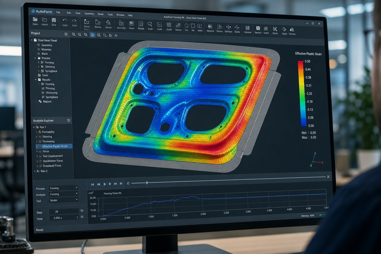
Modern die design simulation software uses finite element analysis (FEA) to digitally replicate what happens when a sheet metal blank contacts the die surfaces under press tonnage. The software meshes the blank into thousands of discrete elements, assigns material properties (yield strength, strain hardening behavior, anisotropy), and steps through the forming process in incremental time steps. At each increment, it calculates stress, strain, thickness change, and contact conditions across the entire part surface.
What does this reveal? Imagine you are designing a transfer die for a B-pillar reinforcement in 980 MPa dual-phase steel. The simulation shows thinning exceeding 25% at a transition radius, placing that zone above the forming limit curve. That is a predicted split. In the same run, compressive stresses accumulate in an unsupported flange, indicating wrinkle risk. Both problems are visible on screen before a single machining program is written.
This proactive approach is exactly what virtual die tryout workflows are designed to accomplish: detect and resolve potential defects during the design phase rather than during physical tryout, when corrections become time-consuming and costly. Simulation allows engineers to test different blank shapes, draw bead configurations, blank holder forces, and press speeds in hours rather than weeks, iterating digitally until the process window is robust.
Springback Compensation in Die Face Design
Springback is elastic recovery. When the press opens and forming forces release, the sheet metal partially springs back toward its original flat state. In mild steel, this deviation might be 1 to 2 degrees on a flange angle. In 980 MPa AHSS, it can reach 8 to 12 degrees, with additional twist and wall curl that distorts the entire part beyond assembly tolerance.
A springback compensation stamping die does not simply form the part to nominal geometry. It intentionally over-forms, bending surfaces past their target position by a calculated amount so that after elastic recovery, the part relaxes into the correct shape. This sounds straightforward in principle. In practice, it requires iterative simulation loops where the software predicts springback deviation, morphs the die surfaces in the opposite direction, re-simulates, and checks convergence.
Surface morphing is the core technique. The die face geometry is displaced by a vector field derived from the springback prediction, essentially pushing each point on the tool surface by the inverse of its predicted dimensional error. Advanced approaches use CAE-based deviation vector fields to define one-to-one node correspondence between the nominal CAD surface and the compensated geometry, ensuring smooth, manufacturable tool surfaces even when springback patterns are complex. This methodology works for both virtual compensation during design and scan-based compensation during physical tryout, where scanned cloud-of-points data from actual stampings drives the morphing corrections.
Multiple compensation iterations are typical. A first pass might reduce springback from 4 mm to 1.5 mm. A second pass brings it under 0.8 mm. The goal is net-shape accuracy after the press opens, not during the forming stroke itself.
Virtual Tryout and Process Optimization
Stamping die simulation extends beyond single-operation feasibility checks. A full virtual tryout replicates the entire press-die-material system as a digital twin: every forming operation in sequence, with intermediate springback between stations, trim operations, and final springback after the last hit. Engineers can evaluate how changes in one station propagate downstream, something that is extremely difficult to diagnose on a physical press line.
This digital twin approach enables optimization of variables that are expensive to adjust physically:
- Draw bead geometry and position - Controls material flow into the die cavity, preventing both wrinkles (too little restraint) and splits (too much restraint).
- Blank shape and size - Optimized contour reduces scrap, eliminates edge cracking, and ensures sufficient material for flanging operations.
- Blank holder force profile - Variable force during the stroke manages material feed rate at different stages of deformation.
- Press speed and slide motion - Particularly critical for servo press applications where ram velocity through the forming zone affects strain rate sensitivity in aluminum and AHSS.
Process robustness analysis adds another layer. By running the simulation across a range of material property variations (thickness tolerance, yield strength scatter, friction coefficient changes), engineers identify whether the process window is wide enough to tolerate real-world variation or whether it will produce rejects whenever incoming coil properties shift slightly.
Key Simulation Outputs Every Die Engineer Should Evaluate
A single simulation run generates a rich dataset. Knowing which outputs matter and what they indicate is what separates experienced engineering teams from those who simply "run the software" without extracting actionable conclusions:
- Forming Limit Diagrams (FLD) - Plot major and minor strain at every element against the material's failure curve. Elements above the curve indicate split risk. Elements in the compression zone indicate wrinkle tendency.
- Thinning maps - Show percentage thickness reduction across the part. Critical thresholds vary by material, but thinning beyond 20-25% in AHSS typically signals imminent failure.
- Springback deviation contours - Visualize dimensional error after elastic recovery, typically displayed as color-mapped distance from nominal geometry. Guides compensation strategy and identifies areas needing restrike operations.
- Wrinkle indicators - Identify zones where compressive stress exceeds the material's buckling threshold, predicting surface waves or folds that may not flatten in subsequent operations.
- Contact pressure distribution - Reveals where die surfaces experience highest wear loading, informing decisions about surface coatings and insert placement.
- Draw-in maps - Track how much material flows inward from the blank edge during forming. Mismatch between predicted and actual draw-in is a primary diagnostic when physical tryout results deviate from simulation.
Why Material Characterization Determines Simulation Accuracy
Every output listed above is only as reliable as the material data feeding the model. Standard tensile test results (yield, UTS, elongation) are insufficient for high-fidelity stamping die simulation. Accurate predictions require full hardening curves across strain rates, yield surface parameters capturing directional anisotropy (Lankford r-values at 0, 45, and 90 degrees), and friction coefficients measured under realistic contact pressures and velocities.
This challenge intensifies for AHSS and aluminum alloys. Dual-phase steels exhibit complex hardening behavior where martensite and ferrite deform at different rates. Aluminum alloys display strong strain-rate sensitivity and different friction characteristics than steel. When simulation teams use generic material cards instead of tested, grade-specific data, their springback predictions can deviate 30 to 50% from physical reality, rendering the entire compensation strategy unreliable.
Investing in proper material characterization, including bulge tests, friction tests, and cyclic loading data for springback modeling, is not an optional refinement. It is the foundation that makes virtual die engineering trustworthy enough to reduce physical tryout from weeks of iteration to days of confirmation.
Of course, even the most accurate simulation still produces a virtual prediction. The moment physical steel meets physical tooling on a real press, new variables emerge that no model captures perfectly. That transition from digital confidence to physical validation is where die tryout methodology determines whether the simulated promise translates into production reality.
Die Tryout, Validation, and Production Approval
Simulation promised a robust process window. The die build followed CAD geometry within machining tolerances. Yet the first panel off the press shows a split at the draw radius and 3 mm of springback deviation on the critical flange. What happened? The stamping die tryout process is where digital predictions meet physical reality, and it is the phase where most pre-production failures either get resolved or spiral into costly delays.
Tryout is not a single event. It is a structured sequence of escalating validation steps, each with defined acceptance criteria and corrective feedback loops. Teams that treat it as a formality launch late. Teams that engineer their tryout methodology with the same rigor as their die design launch on time.
Die Tryout Process and Panel Evaluation
The stamping die tryout process begins the moment the completed tool arrives at the tryout press. A first-hit operation produces the initial stamped panel at reduced tonnage and slow speed, allowing engineers to assess gross formability without risking catastrophic tool damage. You are looking for obvious splits, severe wrinkling, or gross misalignment between upper and lower tool halves.
After first-hit corrections, the die moves to home-line tryout on the production press (or a press that matches production specifications in tonnage, bed size, and slide motion). This step matters because press deflection characteristics, bolster flatness, and ram parallelism all influence how the die performs. A tool that runs cleanly on a stiff tryout press can produce dimensional deviations on a production line with different structural compliance.
Successive refinement follows. Each tryout loop produces sample panels that get measured, evaluated, and compared against simulation predictions. As FormingWorld notes, matching draw-in between simulation and physical results is a primary diagnostic. If material flow into the die cavity differs from predicted values, the effective restraint from beads, binder pressure, and friction is not replicating the engineered intent, and root-cause investigation begins there.
Validation Criteria and Approval Milestones
A panel that forms without splits is not automatically approved. Die validation automotive standards require passing a stack of criteria before production sign-off:
- GD&T conformance - Coordinate measuring machine (CMM) or optical 3D scanning verifies every critical dimension against the part drawing. Typical tolerances for BIW panels range from +/- 0.5 mm on mating surfaces to +/- 1.0 mm on non-critical flanges.
- Surface quality evaluation - For Class-A panels, stoning (running an oilstone across the surface) and Abralux inspection (brushed-light examination) reveal low spots, sink marks, and surface waviness invisible to the naked eye. These defects become visible after paint and are not acceptable on exterior panels.
- Process capability studies - Running 30 or more consecutive panels and measuring critical dimensions establishes Cp and Cpk indices. Most OEMs require Cpk of 1.33 or higher at minimum, with 1.67 preferred for safety-critical dimensions. A Cpk below threshold means the process produces too many out-of-spec parts even when the mean is centered.
- OEM sign-off protocols - Production Part Approval Process (PPAP) or equivalent submission packages document material certifications, dimensional reports, capability data, and process flow diagrams. Only after full documentation review does the OEM release the die for production use.
Tryout quality directly determines production launch timing and cost. Every additional tryout loop adds weeks to the program timeline and tens of thousands in rework expense, while each unresolved issue at this stage becomes a recurring production defect.
Standard Tryout-to-Approval Sequence
The stamping die approval process follows a defined progression. While specific milestones vary by OEM, the fundamental sequence is consistent across the industry:
- Die delivery and mechanical inspection - Verify die construction matches design intent: check machining dimensions, guide clearances, spring loads, and fastener torque.
- First-hit at reduced tonnage - Produce initial panels at 50-70% press capacity to assess gross formability and identify major issues before full-force operation.
- Spotting and blue-matching - Apply spotting compound (Prussian blue) to verify uniform contact between die surfaces and sheet metal. Adjust by hand grinding until contact exceeds 80% across all critical forming areas.
- Progressive tonnage increase - Step up to full production tonnage while monitoring for splits, excessive thinning, or surface defects at each increment.
- Home-line tryout - Run the die on the actual production press line to capture press-specific deflection, speed, and feed system interactions.
- Dimensional evaluation and springback measurement - CMM or scan all critical features. Compare against nominal and apply compensation corrections where deviations exceed tolerance.
- Surface quality audit - Stone and inspect Class-A panels. Identify and correct low spots, surface distortion, and die marks through polish or geometry adjustment.
- Process capability run - Produce a statistically significant batch (typically 30-300 parts) at production speed and measure Cp/Cpk on key characteristics.
- PPAP submission and OEM approval - Package all data, submit for customer review, and obtain formal sign-off authorizing production use.
Common Tryout Issues and Corrective Actions
Even well-simulated dies encounter problems during physical validation. The difference between a successful tryout and a months-long rework spiral is how quickly the team diagnoses root causes and applies the right corrective action.
Splits appear as fractures in high-strain zones, typically at draw radii or transition areas. Corrective actions include increasing die radii, adding draw beads to redirect material flow, adjusting blank size, or polishing and re-coating high-friction surfaces. If the split location matches simulation predictions, the digital model already contains the answer. If it does not, the physical tool may have deviations from design intent that need investigation.
Wrinkles result from insufficient blank holder pressure or excessive material flow into unsupported areas. Spotting corrections, increased binder tonnage, or adding local pressure pads resolve most cases. Severe wrinkling in flange areas may require welding and re-machining die surfaces to add material restraint features.
Springback deviation beyond tolerance demands die face compensation. Engineers scan the actual part, compare to nominal, and apply inverse morphing vectors to the die surfaces. This typically requires welding material onto under-formed areas and re-machining to compensated geometry. Multiple iterations are common for AHSS parts.
Surface defects such as die marks, scratches, or low spots trace back to contact interference, insufficient polishing, or localized high spots on the tool surface. Spotting with contact compound identifies the offending areas, which are then ground, polished, or lapped until uniform panel contact is achieved.
The speed and cost of resolving these issues depends heavily on the die shop's in-house capabilities. A facility with its own tryout press, CMM lab, and skilled die makers can iterate in days. One that ships tools to external tryout locations loses weeks per loop. This is why tryout infrastructure is not an afterthought but a core capability that separates effective die programs from troubled ones, and a critical factor when evaluating which manufacturing partner to trust with your tooling investment.
Maintenance, Failure Modes, and Die Lifecycle Management
A die that passes tryout and earns production approval is not a finished asset. It is the beginning of a lifecycle measured in millions of press strokes, where every cycle degrades cutting edges, fatigues stressed radii, and wears guide surfaces incrementally. The difference between a tool that delivers its full intended production volume and one that fails catastrophically mid-run comes down to stamping die maintenance discipline. Yet most shops conflate maintenance with repair, reacting to failures rather than preventing them.
As die engineering expert Art Hedrick distinguishes clearly: if your daily activities include fixing broken pads, welding damaged sections after dowels fall out, or digging stuck parts from a draw die, that is repair. True preventive maintenance involves sharpening cutting sections on schedule, inspecting for wear before it causes defects, and replacing components before their expected life cycle ends. Running a die repair program disguised as maintenance guarantees premature tooling death.
Preventive Maintenance Schedules and Key Inspection Points
Effective stamping die maintenance operates on stroke-count intervals, not calendar time. A die running 40 strokes per minute on a two-shift schedule accumulates roughly 38,000 hits per day. Within a week, that is over 190,000 cycles of mechanical stress on every cutting edge, guide bushing, and spring. Scheduling inspections by date instead of accumulated strokes ignores the actual wear driver entirely.
Stroke-count-based intervals vary by operation severity. Blanking and piercing stations in progressive dies typically need sharpening every 50,000 to 150,000 strokes when processing mild steel, dropping to 20,000 to 60,000 strokes for AHSS grades. Forming stations wear more gradually but need surface inspection and lubrication system verification at similar intervals. Guide pins and bushings should be measured for clearance growth every 250,000 to 500,000 strokes, with replacement triggered when clearance exceeds design spec by 0.02 mm or more.
Key inspection points during scheduled maintenance include:
- Cutting edge condition - Check all punch and button edges for burr height on stamped parts. When burr exceeds 0.1 mm (material-dependent), sharpening is overdue. Use the right grinding wheel for the tool steel grade, as loaded wheels cause heat buildup that softens or cracks hardened sections.
- Spring integrity - Inspect nitrogen cylinders for pressure loss and coil springs for fatigue fracture. Replace before the expected life cycle ends. If springs break repeatedly at short intervals, the root cause is likely a design problem such as excessive deflection beyond effective rate.
- Guide component wear - Measure pin-to-bushing clearance with plug gauges. Excessive play causes punch-to-die misalignment that accelerates edge breakdown and generates burrs.
- Fastener security - Check all screws for tightness. Look for missing or loosened dowel pins that allow section shifting under stamping loads.
- Surface condition - Inspect forming radii, wear plates, and cam surfaces for galling marks, scoring, or coating degradation. Regrind and recoat before surface damage transfers to stamped parts.
- Lubrication system - Verify that in-die lubrication channels are clear, nozzles are not clogged, and lubricant reaches all high-friction contact zones. Dry contact accelerates both galling and abrasive wear exponentially.
- Slug and debris removal - Clean all slug passages, drop holes, and scrap channels. Slug buildup causes slug pulling, which leads to die crashes and punch breakage.
After every service, dry the die completely to prevent rust on precision-ground surfaces, confirm all safety guards are in place, and document the work performed with the current stroke counter reading. This documentation builds the service history that makes future failure analysis possible.
Common Failure Modes and Root Cause Diagnosis
Stamping die failure modes fall into distinct categories, each with different visual signatures and different root causes. Treating every failure the same way, say, by simply resharpening and hoping for the best, guarantees recurrence. A structured failure analysis approach starts with identifying which mode is present before jumping to corrective action.
Chipping presents as small fragments breaking away from cutting edges or forming radii. You will see irregular, conchoidal fracture surfaces rather than smooth wear patterns. Root causes include insufficient toughness in the tool steel for the applied load (D2 used where S7 is needed), improper heat treatment leaving residual stress, sharp corners acting as stress risers, or excessive cutting clearance that generates high snap-through loads. Chlorinated lubricants used with carbide tooling can also attack cobalt binders and trigger surface chipping over time.
Galling appears as material transfer from the sheet metal onto the die surface, creating raised lumps that scratch subsequent panels. The visual indicator is a buildup of adhered workpiece material on forming radii or draw surfaces, often with corresponding score marks on stamped parts. This mode dominates when forming aluminum, galvanized steels, or stainless grades where adhesive affinity between sheet and tool is high. Inadequate lubrication, excessive blank holder force, or degraded PVD coatings all amplify galling tendency.
Cracking manifests as linear fractures propagating through die components, sometimes catastrophically. Fatigue cracks grow gradually from stress concentrators like sharp internal corners, stamp marks, or abrupt cross-section changes. Thermal cracks present as networks of fine surface lines (heat checking) caused by cyclic heating and cooling during high-speed stamping. Design faults that place thin sections adjacent to thick sections, or features with fillets that are too small, create the geometry that initiates cracking during heat treatment or early service life.
Fatigue failure develops over extended service without obvious warning. Repeated cyclic loading below the material's ultimate strength still causes progressive microcrack nucleation and growth. Die components subjected to shock loading, such as blanking punches and cam drivers, are most susceptible. Visual indicators are subtle until final fracture: slight deformation at loaded surfaces, fine surface crazing under magnification, or gradual dimensional drift in stamped parts as the die component deforms plastically under accumulated cycles.
The following table maps these stamping die failure modes to their diagnostic indicators and corrective paths:
| Failure Mode | Root Causes | Visual Symptoms | Corrective Action |
|---|---|---|---|
| Chipping | Insufficient toughness, sharp corners, improper heat treatment, excessive clearance | Irregular edge fractures, conchoidal breakaway surfaces, burr increase on parts | Switch to tougher steel grade, add radii to stress risers, review heat treatment cycle, correct clearance |
| Galling | Material adhesion, inadequate lubrication, coating failure, excessive pressure | Built-up material transfer on die surface, scoring on stamped panels | Repolish and recoat die surface, improve lubrication delivery, reduce binder force, apply anti-galling PVD or TD coating |
| Cracking (thermal) | Cyclic thermal loading, insufficient cooling, high-speed operation | Network of fine surface lines (heat checking), progressive deepening over time | Improve cooling, reduce press speed, resurface and apply thermal-resistant coating, verify material tempering |
| Cracking (mechanical) | Stress concentrators, design errors (sharp corners, thin walls), overloading | Linear fractures from corners or section changes, sudden component failure | Redesign with proper fillets, increase section thickness, verify tonnage is within design limit |
| Fatigue failure | Cyclic loading exceeding endurance limit, shock loading, accumulated microcracking | Gradual dimensional drift, fine surface crazing, sudden catastrophic fracture after extended service | Replace component before predicted fatigue life, redesign for reduced stress concentration, add pre-load relief features |
| Abrasive wear | Hard sheet material (AHSS), abrasive coatings (galvannealed), insufficient surface hardness | Gradual material loss from die surfaces, increasing die clearance, edge rounding | Upgrade to PM tool steel or carbide inserts, apply TD or PVD coating, tighten sharpening intervals |
Repair vs. Replace Decision Framework
When a failure is diagnosed, the next question is economic: repair the existing component, replace it with a new insert, or rebuild the entire die section? The answer depends on three variables: remaining production volume, repair feasibility, and the risk of recurrence.
Weld repair makes sense when damage is localized, the base material is weldable without introducing excessive hardness variation, and the remaining production volume justifies the cost. Typical applications include building up worn forming radii, filling localized chipping on trim edges, and restoring cam driver surfaces. However, weld repairs alter the heat-affected zone metallurgy and can introduce residual stress that accelerates future cracking if not properly stress-relieved and re-machined.
Insert replacement is the preferred path when wear or damage occurs in a predictable, high-contact zone that was designed for replaceable inserts from the start. Carbide trim inserts, for example, are intended to be swapped at defined intervals. If the die was not originally designed with replaceable inserts at the failure location, retrofitting them is worth considering when the failure mode will recur regardless of repair quality.
Full die rebuild becomes the rational choice when multiple failure modes are present simultaneously, the die has accumulated enough cumulative rework that dimensional integrity is questionable, or the remaining production volume exceeds what repairs can reliably deliver. A rebuild using updated material grades and surface treatments can also incorporate lessons learned from the die's service history, effectively creating a next-generation tool rather than restoring the original design.
Die Protection Systems for Life Extension
The most cost-effective maintenance strategy is preventing catastrophic damage in the first place. Die protection systems use in-press sensors and electronic controllers to detect die-threatening events and stop the press before a single bad stroke destroys weeks of repair labor.
A well-implemented die protection program monitors conditions such as misfeed detection (strip not advancing to pilot position), part ejection verification (confirming the previous part cleared before the next stroke), short feed or overfeed events, strip buckle, end-of-stock, and cam return confirmation. Modern resolver-based controllers provide timing accuracy to one-third of a degree of crankshaft rotation, fast enough to catch a misfeed event and halt the press before the ram reaches the work zone.
Sensors permanently installed on each die, wired through a die-mounted junction box to a press-mounted interface, eliminate setup errors and cable wear that plague loose-wire approaches. The critical principle: permanently install a sensor on each die that needs it rather than moving sensors between tools. Compared to the cost of a die crash, sensors are inexpensive. Even without a crash event, the setup time saved by permanent installation quickly offsets the hardware investment.
Nuisance stops, where the system halts the press when no real problem exists, are the primary threat to program success. They erode operator confidence until the system gets ignored or disabled entirely. Avoiding them requires proper bench testing of every sensor before installation, using all available tolerance in sensor positioning rather than setting detection thresholds unnecessarily tight, and ensuring that sensors are fixed in position so no run-time adjustment is needed.
Stroke counters integrated with the protection controller provide the data backbone for condition-based maintenance. Rather than relying on calendar schedules or guesswork, maintenance triggers fire automatically when accumulated strokes reach predefined thresholds for sharpening, spring replacement, or full inspection. This transforms die life extension from reactive firefighting into a predictable, engineered outcome.
Maintenance infrastructure, failure diagnosis capability, and protection system sophistication are all attributes that distinguish one die partner from another. When evaluating which manufacturer or service provider to trust with your production tooling, these lifecycle capabilities matter as much as initial design and build quality.
Selecting a Stamping Die Manufacturing Partner
Maintenance programs, failure diagnosis, and protection systems all assume something fundamental: the die was well-built in the first place. A tool with design flaws embedded at the concept stage, or machining errors introduced during construction, will consume maintenance budgets no matter how disciplined your inspection intervals are. That reality makes stamping die supplier selection one of the highest-leverage decisions in any vehicle program. The wrong partner does not just deliver a late tool. They deliver a tool that never quite works right, bleeding rework cost and launch delay across the entire program lifecycle.
So how do you evaluate a metal stamping dies manufacturer before committing tooling budget? Price per kilogram of tool steel is the metric most purchasing teams default to. It is also the least predictive of program success. What actually matters is whether the supplier can engineer a robust process, build it accurately, prove it works, and support it through production. That requires a specific set of capabilities, and knowing what to look for separates informed sourcing from hopeful procurement.
Key Capabilities to Evaluate in a Die Manufacturer
Think of stamping die supplier selection as a systems evaluation rather than a commodity purchase. You are not buying steel and machining hours. You are buying the ability to deliver production-ready tooling that hits dimensional targets on first tryout or close to it. The following capabilities determine whether a custom automotive stamping die maker can deliver on that promise:
- In-house forming simulation - A supplier running FEA-based feasibility analysis and springback compensation internally can identify and resolve problems before machining starts. Outsourced simulation adds communication lag and disconnects the people who design the die from the people who predict its behavior.
- 5-axis CNC machining - Complex die face geometries, especially for AHSS springback-compensated surfaces, require 5-axis capability to machine accurately in a single setup. Suppliers limited to 3-axis work introduce more setups, more tolerance stack, and more risk of surface discontinuities.
- In-house tryout press - This is non-negotiable for serious programs. A supplier with their own tryout press iterates corrections in days. One that ships tools to external facilities loses weeks per loop and cannot maintain tight feedback between die makers and tryout results.
- Metrology lab with CMM and 3D scanning - Dimensional validation requires coordinate measurement capability on-site. Suppliers who can scan tryout panels immediately after pressing, overlay results against CAD, and generate deviation maps in hours rather than days compress the entire validation timeline.
- OEM approval history - A supplier who has successfully completed PPAP submissions for your target OEM (or comparable programs) already understands the documentation requirements, capability thresholds, and sign-off protocols. This institutional knowledge eliminates learning-curve delays during your program.
- Engineering change responsiveness - Late design changes are a reality in automotive programs. Evaluate how the supplier handles ECNs: do they have the CAD/CAM infrastructure to incorporate changes quickly, and do they communicate cost and timing impact transparently rather than absorbing changes silently and delivering late?
Beyond individual capabilities, look for integration between them. A supplier with simulation, machining, tryout, and metrology under one roof can close the loop between predicted performance and actual results faster than one who subcontracts any of those steps. Each handoff between facilities introduces delay, communication loss, and accountability gaps.
Collaboration Models from Design Through Production Support
How the supplier engages with your engineering team matters as much as what equipment they own. Two dominant collaboration models exist, and the right choice depends on your program's maturity and your team's internal resources.
Full-service (build-to-spec) partnerships give the die supplier design authority. You provide part geometry, material specification, volume targets, and quality requirements. The supplier engineers the die concept, runs simulation, designs the tooling, builds it, and validates it through tryout. This model works best when your team lacks dedicated die engineering resources, when you want to leverage the supplier's forming expertise, or when the program benefits from manufacturing-driven design optimization. The supplier assumes more engineering risk, but you gain access to their accumulated process knowledge across similar part families.
Build-to-print partnerships keep design authority with your team. You supply complete die design data, CAD models, material specifications, and tolerances. The supplier executes fabrication precisely to your documentation without altering geometry, materials, or process parameters unless formally approved. This model suits programs where IP sensitivity is high, designs are mature and fully validated, or your internal die engineering team has deep expertise and wants tight configuration control. As industry analysis confirms, the determining factor is whether design control or cost optimization is the higher priority for your program.
Many successful programs blend both models. Initial feasibility and die concept development might follow a full-service approach, leveraging the supplier's simulation expertise and forming know-how. Once the design is frozen and validated, production die construction shifts to build-to-print execution with tight change control. This hybrid captures the benefits of collaborative engineering without surrendering configuration authority during production.
For teams evaluating full-service partners across structural, chassis, interior, and truck-related stamping programs, YICHEN's automotive division offers a useful reference point. They support OEM, Tier-1, and Tier-2 engineering teams with stamping and sheet metal fabrication, publishing process case studies that demonstrate capability across multiple part families. Reviewing documented case studies from potential suppliers, whether YICHEN or others on your shortlist, gives you tangible evidence of how they handle real program challenges rather than relying solely on capability claims in a sales presentation.
Ultimately, the right stamping die manufacturing partner is not the cheapest quote or the fastest promised lead time. It is the team whose engineering depth, equipment capability, and collaboration model align with your program's complexity and your organization's internal resources. Get that alignment right, and the die arrives production-ready. Get it wrong, and you are back to the article's title: your auto stamping die fails before production starts.
Frequently Asked Questions About Auto Stamping Dies
1. What is an auto stamping die and how does it work?
An auto stamping die is a matched set of precision-machined upper and lower tool steel components mounted in a press. The upper half (punch) descends into the lower half (die block), forcing sheet metal to conform to the cavity geometry through controlled cutting, bending, and forming. A blank holder clamps material edges to manage metal flow, while guide pins maintain alignment within tolerances as tight as 0.0001 inches. This cold-forming process converts flat sheet metal into three-dimensional automotive parts in a single stroke or series of strokes, producing everything from small brackets to full body panels.
2. What are the main types of stamping dies used in automotive manufacturing?
Automotive manufacturing relies on four primary die types. Progressive dies feed continuous coil through multiple stations for high-volume small parts like brackets and clips. Transfer dies move individual blanks between stations for large structural components such as door inners and floor pans. Compound and combination dies perform simultaneous cutting and forming for precision flat parts. Tandem press lines use multiple independent presses in series for Class-A exterior panels like hoods and fenders. Selection depends on part size, draw depth, production volume, surface quality requirements, and material grade.
3. How do you choose the right stamping die type for a specific automotive part?
Choosing the right stamping die type starts with three primary variables: production volume, part geometry, and economics. Progressive dies become cost-effective above 50,000 to 100,000 annual units for parts under 300 mm. Transfer dies suit large parts with draw depths exceeding 50 mm at volumes above 25,000 units. Material grade adds constraints since AHSS above 780 MPa requires more forming stages and higher tonnage, while aluminum demands adjusted clearances and servo press speed control. Budget and lead time also factor in, as progressive dies need 12-20 weeks versus 20-30+ weeks for tandem line tooling. Partners like YICHEN (yichen-group.com/automotive) can provide process case studies to help validate die type decisions across structural and chassis applications.
4. What causes stamping dies to fail prematurely and how can failures be prevented?
Premature stamping die failure stems from four primary modes: chipping (insufficient toughness or sharp stress risers), galling (material adhesion from inadequate lubrication or coating degradation), cracking (thermal cycling or mechanical stress concentrators), and fatigue (accumulated microcracking from cyclic loading). Prevention requires matching tool steel grade to the stamping operation, implementing stroke-count-based maintenance schedules rather than calendar-based inspections, applying appropriate surface coatings like TD or PVD for AHSS applications, and installing die protection sensors that detect misfeeds or ejection failures before catastrophic damage occurs.
5. What should you look for when selecting a stamping die manufacturing partner?
Evaluate a stamping die manufacturer as a systems partner, not a commodity supplier. Critical capabilities include in-house forming simulation for pre-build problem detection, 5-axis CNC machining for complex compensated surfaces, an on-site tryout press for rapid iteration, a metrology lab with CMM and 3D scanning, documented OEM approval history, and responsive engineering change management. Integration between these capabilities under one roof compresses timelines significantly. Full-service partners like YICHEN support OEM through Tier-2 teams with stamping and fabrication across structural, chassis, and interior part families, offering published case studies as evidence of real program execution.


