


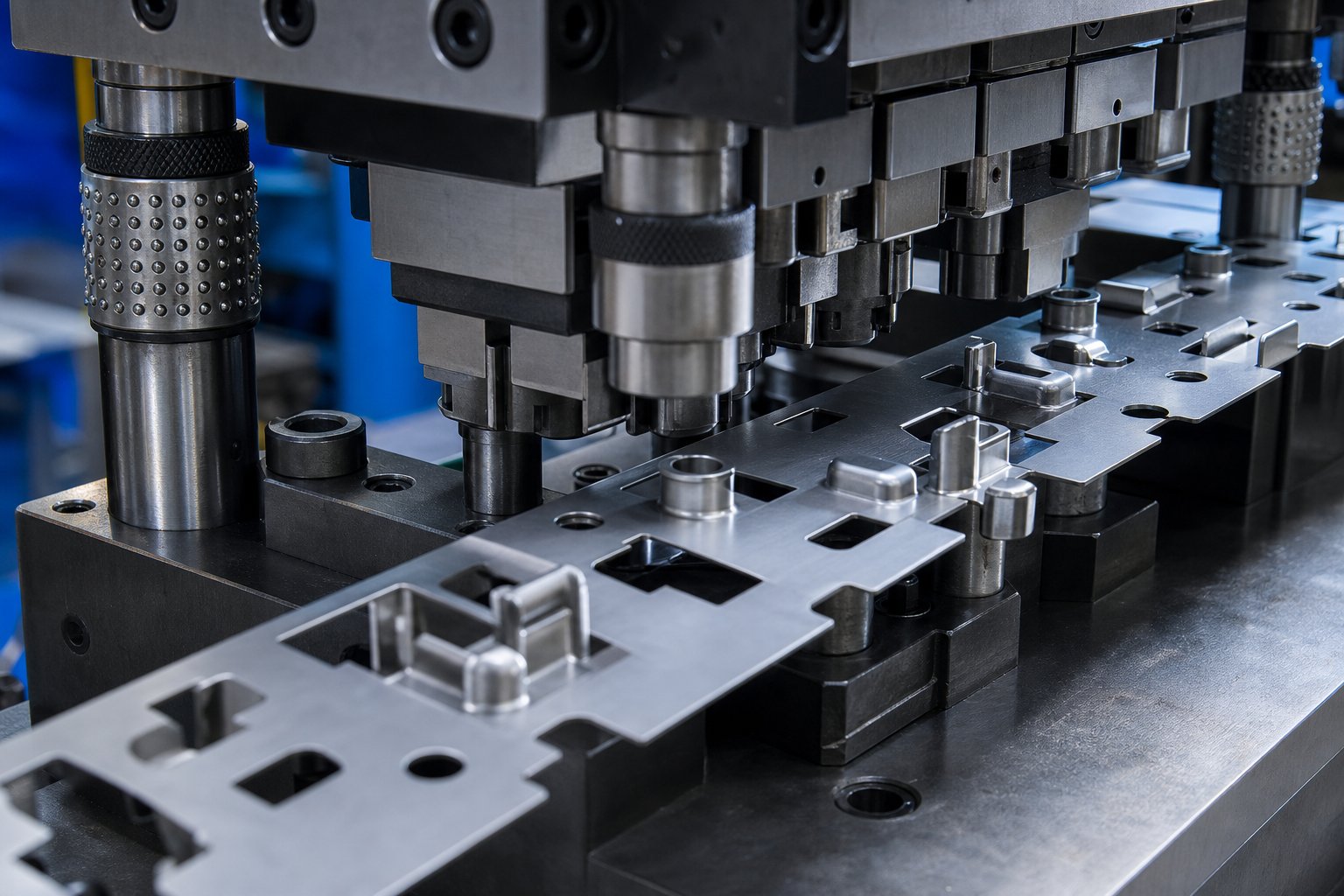
What Bypass Notches Are and Why They Matter in Stamping Dies
When you run a progressive stamping die at production speed, every formed feature on the strip has to travel through downstream stations without crashing into tooling. That single requirement drives one of the most practical design decisions a tool and die maker faces: where and how to cut bypass notches.
Definition of Bypass Notches in Progressive Dies
A bypass notch is a deliberate material removal in the carrier strip of a progressive die that creates clearance for previously formed features to pass through subsequent stations without colliding with punches, die blocks, strippers, or lifters.
The purpose of bypass notches in stamping dies is straightforward. As the strip indexes forward, features like lances, embossments, drawn cups, and bent tabs protrude above or below the strip plane. Without a clearance path, those features slam into downstream tooling components and the press jams. Bypass notches in sheet metal forming give each protruding feature a safe corridor to travel through, keeping the strip moving and the press running.
Why Interference Prevention Is a Core Die Design Challenge
Interference between formed features and die components is not a minor nuisance. It causes strip jams, scrapped parts, broken punches, and unplanned downtime that eats into production targets. Every tool and die professional involved in design, setup, or maintenance needs a clear understanding of how bypass notches prevent interference in a stamping die, because the alternative is reactive troubleshooting on a stopped press.
This article breaks down the mechanics, types, design process, material considerations, and failure modes of bypass notches in sheet metal forming. The goal is to give you a complete, practical reference for getting interference prevention right at the design stage rather than chasing problems in production.
Understanding How Strip Interference Develops at Forming Stations
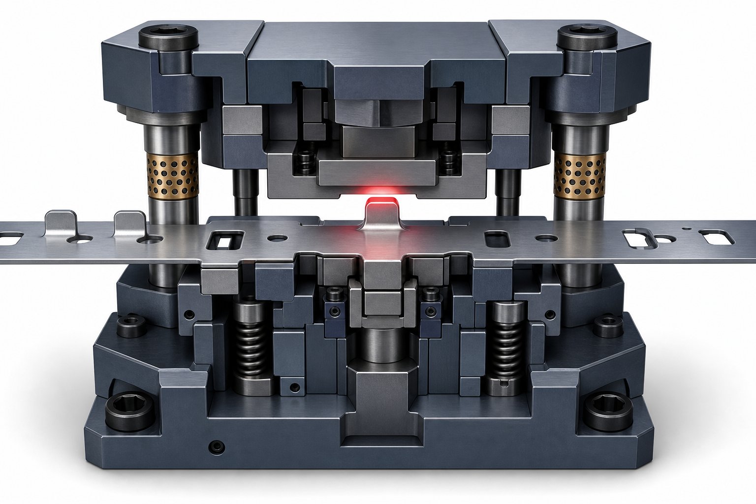
Imagine a strip of sheet metal advancing through a progressive die, station by station, at hundreds of strokes per minute. Each station performs a specific metal forming operation: one punches a lance, the next draws a cup, another bends a tab. Every one of these operations permanently displaces material above or below the strip plane. The strip keeps moving forward, carrying those protruding features with it, and that is exactly where the collision risk begins.
How Formed Features Create Collision Risks During Strip Progression
In a progressive die, the strip indexes forward by one pitch length each press cycle. Features formed upstream now occupy space that downstream tooling components also need. A drawn cup sitting below the strip plane moves directly toward the next station's die block face. A bent tab standing above the strip travels straight into a stripper plate. The yielding force applied during forming has permanently reshaped the material, and that new geometry does not shrink back to fit neatly through the next station.
The problem compounds in dies with many stations. Each additional forming operation adds another protruding feature that must clear every subsequent station it passes through. A die maker designing a twelve-station progressive tool may need to track interference paths for features created as early as station two all the way through station eleven.
Here are the most common interference scenarios that develop during strip progression:
- Upward-facing forms (lances, embossments, bent tabs) colliding with stripper plates or upper punches as the die closes
- Downward-facing draws or extruded features contacting die block surfaces or lower tooling during strip advancement
- Lateral bends or coined flanges catching on guide rails, preventing smooth strip travel between stations
- Formed features striking spring-loaded lifter pins that elevate the strip for feeding
Consequences of Unresolved Interference in Production Runs
When a formed feature hits a downstream component, the results are immediate and costly. The strip jams, stopping the press mid-cycle. Parts in process get crushed or deformed beyond tolerance. Punches snap, die blocks chip, and strippers bend. According to Metalforming Magazine, even seemingly minor timing or clearance issues in progressive dies can generate unnecessary tonnage that damages both the die and the press itself.
Unplanned downtime from interference-related jams does not just cost repair hours. It disrupts production schedules, scraps material, and forces reactive troubleshooting under pressure. The smarter path is prevention by design, addressing every potential collision in the strip layout before the die ever hits the press. That design-stage thinking is precisely what drives bypass notch geometry, placement, and sizing decisions.
How Bypass Notches Mechanically Prevent Interference
Strip interference is a geometry problem, and bypass notches solve it with geometry. The principle is deceptively simple: remove a section of strip material at a precise location so that when the strip advances, the protruding formed feature occupies the space where material used to be. No material in the path means no collision with downstream tooling. The challenge lies in calculating exactly how much material to remove, where to remove it, and how that removal interacts with the strip's structural behavior as it feeds through the die.
Creating a Clearance Envelope Through Material Removal
Think of the clearance envelope as a three-dimensional corridor that a formed feature needs to travel through without touching anything. The bypass notch defines the floor, walls, and ceiling of that corridor by eliminating the strip material that would otherwise occupy it.
The notch geometry must account for three dimensions of the formed feature:
- Height or depth - how far the feature protrudes above or below the strip plane
- Footprint - the plan-view area the feature occupies along and across the strip
- Clearance margin - additional space beyond the feature envelope to accommodate variation in feed accuracy, material springback, and press deflection
The notch does not need to be dramatically larger than the feature it clears, but it must account for real-world conditions. Material behavior under stress follows an s-s curve (stress-strain curve) that reveals how the strip deforms elastically before reaching permanent yield. This matters because the elastic modulus of the strip material determines how much the carrier flexes under feeding forces, which can shift the formed feature slightly relative to its nominal position. A notch sized only to the theoretical feature envelope, with no clearance margin for elastic deflection, risks intermittent contact under production conditions.
The clearance margin typically ranges from 0.5 mm to 2.0 mm beyond the feature boundary, depending on material stiffness, press speed, and the precision of the feeding system. Thicker, stiffer strips with higher yield strength and yield point values tend to hold position more consistently, allowing tighter clearance margins. Thinner, more flexible materials demand larger margins because the strip can sag or flutter between lifters during high-speed feeding.
How Strip Pitch and Feature Geometry Dictate Notch Placement
Notch placement is inseparable from strip pitch - the fixed distance the strip advances with each press stroke. When the strip indexes forward by one pitch, a formed feature created at station N arrives at station N+1. If tooling at station N+1 occupies the same vertical space as that feature, a bypass notch must already exist in the strip at precisely the location where the feature will sit when it reaches that station.
Here is the logic in practical terms. Imagine a drawn cup formed at station 3 that protrudes 8 mm below the strip. At station 4, a lower die block rises to within 2 mm of the strip underside. Without intervention, the cup crashes into that die block when the strip feeds forward. The solution: at station 2 or 3, a notching punch removes material from the strip at a position one pitch length ahead of where the cup will be formed. After the cup is drawn at station 3, the strip advances and the cup moves into the notched opening - passing freely over the station 4 die block.
The relationship between strip pitch, feature size, and notch dimensions follows a clear hierarchy. Strip pitch sets the spatial framework. The formed feature's envelope, including any springback predicted from the material's s-s curve behavior, defines the minimum opening required. Material nesting software for length of material and strip layout helps engineers visualize how notch placement interacts with adjacent features, pilot pin holes, carrier bars, and tie points across the full die length. This software-driven layout planning prevents conflicts between the bypass notch and other critical strip geometry.
Notch dimensions must also respect the progression direction. A notch cut too narrow in the feed direction will not provide enough clearance once the feature indexes into it. A notch that is too wide weakens the carrier strip beyond acceptable limits. Balancing these constraints is what separates a functional bypass notch from one that either fails to prevent interference or creates new feeding problems downstream.
Positive and Negative Bypass Notches Explained
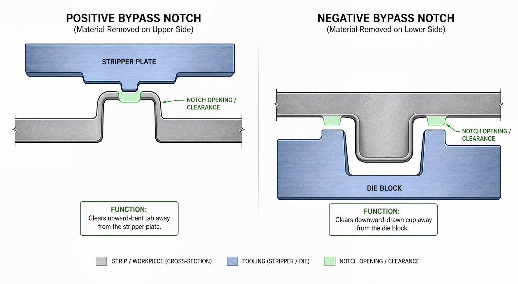
Balancing notch dimensions against strip integrity raises an obvious follow-up question: which direction should the notch open relative to the formed feature? The answer splits bypass notches into two fundamental categories - positive and negative - and the distinction determines whether the clearance corridor sits above or below the strip plane. Understanding negative and positive bypass notches in sheet metal stamping dies is essential for choosing the right interference solution at each station.
Positive Bypass Notches for Upward-Facing Features
A positive bypass notch removes material from the strip on the same side as the formed feature's protrusion. When a lance, embossment, or bent tab projects upward above the strip, the notch opens upward to create clearance against upper die components like stripper plates, cam drivers, or idle punches at the next station.
Picture a tab bent 90 degrees upward at station 4. At station 5, a stripper plate descends to hold the strip flat during a blanking operation. Without clearance, the tab tip crashes into the underside of that stripper. A positive bypass notch - cut into the strip at the tab's indexed position relative to station 5 - removes the material that would otherwise force a collision on the upper side. The tab passes through the open space, the stripper contacts only flat strip, and the press keeps running.
Negative Bypass Notches for Downward-Facing Features
A negative bypass notch works in the opposite direction. It removes material on the side opposite to the feature's protrusion, creating clearance below the strip plane. This type addresses downward-facing features like drawn cups, extruded bosses, or coin-formed depressions that would otherwise contact lower die blocks, lifter surfaces, or ejector pins at downstream stations.
The terminology can feel counterintuitive at first. "Negative" does not mean the notch is less important - it refers strictly to the orientation relative to the forming direction. In practice, negative and positive bypass notches in sheet metal forming stamping dies appear with roughly equal frequency, because most progressive die strips carry features protruding in both directions.
Combining Both Types in Complex Strip Layouts
Complex parts with multi-directional forming often require both notch types within the same strip layout. Consider a part that has an upward embossment at one station and a downward draw at another. Each feature generates its own interference risk at different downstream stations, so the strip may need a positive notch for one and a negative notch for the other - sometimes at the same pitch position along the carrier.
When both types appear together, strip rigidity becomes the critical constraint. Each notch removes material, and combined removals on both sides of the strip at nearby locations can thin the carrier to the point where it buckles or misfeeds. Engineers working with negative and positive bypass notches in a sheet metal stamping die must verify that the total material removal at any cross-section still leaves enough carrier strength to pull the strip reliably through the die.
The table below summarizes the key differences between positive and negative bypass notches:
| Characteristic | Positive Bypass Notch | Negative Bypass Notch |
|---|---|---|
| Direction of formed feature | Upward (above strip plane) | Downward (below strip plane) |
| Typical interference point | Stripper plates, upper punches, cam slides | Die blocks, lifter pins, ejector mechanisms |
| Notch position relative to strip | Opens on the top (same side as protrusion) | Opens on the bottom (opposite side of protrusion) |
| Common applications | Lances, upward bends, embossments, raised tabs | Drawn cups, extruded bosses, downward coin forms |
Choosing the correct notch type is a straightforward decision when a single feature protrudes in one direction. The complexity multiplies with multi-directional parts, where both types coexist and strip carrying strength must be recalculated at every section. That carrying-strength calculation depends heavily on material properties - thickness, yield behavior, and how the strip responds to progressive work hardening around each notch zone.
Material and Thickness Factors That Shape Notch Design
Carrying-strength calculations are not abstract math exercises. They depend directly on what the strip is made of, how thick it is, and how its mechanical properties shift during progressive forming. A bypass notch that works perfectly in 1.0 mm cold-rolled steel may cause strip buckling in 0.5 mm HSLA or leave insufficient clearance in 1.5 mm aluminum. Every material variable feeds back into notch sizing, placement, and the margin between a die that runs cleanly and one that jams under production speed.
Thickness and Yield Strength Effects on Notch Sizing
Material thickness drives bypass notch design in two connected ways. First, thicker stock produces taller formed features. A draw that displaces material downward will protrude farther below the strip in 1.2 mm stock than in 0.6 mm stock, simply because there is more material to displace. That taller feature needs a larger clearance envelope, which demands a wider or deeper notch. Second, thicker strips resist bending and sagging better during feeding, which means the formed feature holds its nominal position more consistently. You can often get away with a tighter clearance margin on thick stock because the strip does not flutter or deflect as much between lifters.
Yield strength introduces the springback variable. When you form a feature in a high-strength material - say, dual-phase 590 or HSLA 420 - the metal springs back more aggressively after the punch retracts. A bend intended to reach 90 degrees may relax to 87 or 85 degrees. A drawn cup may open slightly. That elastic recovery changes the effective feature envelope that the notch must clear. If you sized the notch based on the intended geometry rather than the as-sprung geometry, you may end up with either excess clearance (wasting strip material) or, more dangerously, insufficient clearance at certain feature edges where springback pushed the profile outward.
The relationship between yield strength and springback is well documented in stamping science. As Art Hedrick notes in The Fabricator, if you do not have adequate strain in the metal to meet its yield point - the point at which it permanently plastically deforms - elastic recovery will occur. For bypass notch design, this means the feature envelope used for notch sizing should always reflect the post-springback geometry, not the theoretical punch geometry. The yield strength of steel varies widely across grades, and each grade produces a different springback profile that directly impacts the clearance your notch needs.
Consider a practical example. You are forming an upward lance in 0.8 mm DP780 steel. The punch angle is 45 degrees, but yield stress in this grade causes the lance to spring back to roughly 42 degrees. The tip of the lance now sits slightly higher above the strip plane than the 45-degree geometry would predict. Your bypass notch must accommodate that 42-degree position, not the 45-degree design intent. Ignoring this difference invites intermittent contact at production speed.
Strip Width Constraints and Carrier Integrity Limits
Every bypass notch removes material from the carrier strip, and that removal directly reduces the strip's ability to resist bending during feeding. The carrier must remain strong enough to pull the entire strip - with all its formed features - smoothly through the die without buckling, twisting, or misfeeding. This sets a hard upper limit on notch size.
Strip width is the primary constraint. A narrow strip offers less material to work with, so each notch represents a larger percentage of the available cross-section. Imagine a 40 mm wide strip with a 12 mm bypass notch cut into one side. That single notch reduces the effective carrier width to 28 mm at that cross-section - a 30 percent reduction. In a wider 80 mm strip, the same notch represents only a 15 percent reduction, leaving much more structural margin.
Carrier bar dimensions matter equally. As noted in carrier design guidance from The Fabricator, it takes approximately 10 percent of the part's weight to move it horizontally, and if multiple progressions are involved, the carrier must resist cumulative force without bending. A bypass notch that cuts too deeply into a carrier bar can drop the strip's bending resistance below this threshold, causing the strip to sag between stations and misfeed.
The practical rule: notch width should never exceed 60 to 70 percent of the carrier bar width at any single cross-section. When multiple notches appear close together along the strip, their combined effect on carrying strength must be evaluated as a system, not individually.
Work Hardening and Elastic Recovery Considerations
Forming operations do not just reshape the metal - they change its properties locally. Work hardening increases the yield stress and tensile strength of the deformed zone while reducing ductility. This matters for bypass notch design in two distinct ways.
First, the notching operation itself introduces work hardening at the notch edges. The shearing action that creates the notch plastically deforms a narrow band of material along the cut perimeter. This hardened zone is stiffer and more brittle than the surrounding strip. If a subsequent forming station requires the strip to flex near a notch edge, the hardened material resists that flex and can crack. Engineers need to position notches so their hardened edges do not coincide with areas where the carrier must deform during feeding - particularly in strip layouts that use flex webs or stretch carriers.
Second, work hardening in formed features affects their final geometry. A feature that undergoes significant strain hardening during forming may have a slightly different final profile than an identical feature formed in annealed material. The elastic modulus of metals does not change with work hardening, but the effective yield point rises, meaning less elastic recovery occurs in heavily worked zones. This can actually reduce springback locally, making the feature hold closer to its intended geometry. The interplay between the material modulus (which stays constant) and the elevated yield strength yield stress (which increases with deformation) determines the net post-forming position of the feature.
Elastic recovery after forming deserves separate attention. Even after a formed feature reaches its final position, the strip continues to experience micro-scale elastic movements as it feeds through subsequent stations. Press vibration, lifter action, and acceleration forces during indexing all impose transient loads. The modulus of elasticity of steel - typically around 200 GPa for carbon steels and 70 GPa for aluminum alloys - determines how much the strip deflects under these transient loads. A strip with a lower elastic modulus metals value (like aluminum) will deflect more under the same feeding force, potentially shifting formed features closer to tooling surfaces. This dynamic behavior reinforces the need for adequate clearance margins in bypass notch design, particularly for softer materials running at high press speeds.
These material-driven variables - thickness, yield behavior, work hardening zones, and elastic deflection - form the foundation that every notch dimension rests on. Without accounting for them, a notch designed on paper geometry alone will eventually produce interference on the production floor. Translating these material realities into a reliable design requires a structured engineering sequence, which is exactly where the step-by-step implementation process comes in.
Step-by-Step Design Process for Bypass Notch Implementation
Material properties tell you what the notch must accommodate. The design sequence tells you how to get from raw interference risk to a validated notch geometry that runs reliably at production speed. Tooling engineers do not wing this process - they follow a structured logic that builds from problem identification through dimensional verification, and each step depends on the one before it.
Mapping Interference Risks Across the Strip Layout
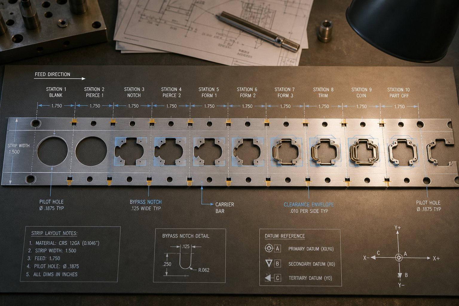
The process starts with a station-by-station audit of the entire strip layout. You are looking for every formed feature that protrudes above or below the strip plane and tracking its path through all downstream stations. A lance formed at station 3 does not just need clearance at station 4 - it needs clearance at every station it passes through until the part separates from the carrier.
Here is the logical design sequence most experienced tooling engineers follow:
- Identify interference-producing stations - Review each forming station and catalog every feature that displaces material out of the strip plane. Note the direction (up or down), height, and footprint of each feature.
- Map the formed feature envelope including springback - Calculate the actual post-springback geometry rather than relying on nominal punch dimensions. The yield limit of steel for your specific material grade determines how much elastic recovery occurs, and that recovery defines the true clearance requirement.
- Determine the required clearance - Add a safety margin (typically 0.5 to 2.0 mm) to the feature envelope. This margin accounts for feed tolerance, press deflection, and dynamic strip movement at speed.
- Define notch geometry - Specify the shape, width, length, and exact position of the notch within the strip. Rectangular notches suit most applications. Irregularly shaped features may need contoured notch profiles, often produced with EDM wire machining for tight-radius corners that conventional punches cannot achieve cleanly.
- Verify that the notch does not weaken the strip below minimum carrying strength - Calculate the remaining cross-section at the notched location and confirm it can resist the feeding forces required to pull the strip through all downstream stations without buckling.
- Confirm notch placement does not conflict with pilots, tie bars, or strip control features - Cross-reference the notch location against pilot pin holes, carrier attachment points, lifter contact zones, and any other features that depend on material being present at that position.
Skipping any step in this sequence invites production problems. Step 2 is where most errors originate - engineers who size notches from CAD geometry rather than post-springback reality end up with clearances that look fine on screen but produce intermittent hits on the press.
Calculating Notch Geometry From Feature Envelope
Defining the notch shape and dimensions is fundamentally an envelope-matching exercise. You take the formed feature's three-dimensional boundary - height, width in the feed direction, and width across the strip - and project it onto the strip plane to define the minimum opening.
The feed-direction dimension is especially critical. The notch must be long enough (in the strip travel direction) so that the formed feature sits entirely within the open space when the strip indexes to the next station. If your strip pitch is 25 mm and the feature footprint spans 10 mm along the feed axis, the notch needs at least 10 mm plus clearance margins on both leading and trailing edges. In practice, most engineers add 1 to 1.5 mm per side, making the feed-direction notch length roughly 12 to 13 mm for that example.
Notch depth (measured perpendicular to the strip edge) depends on how far the feature protrudes across the strip width. Again, the calculation uses the actual post-forming geometry. For high-strength materials where yield strain in steel is reached at relatively low elongation, springback can shift the feature boundary outward by a measurable amount. The steel modulus of elasticity - approximately 200 GPa for most carbon and alloy grades - drives this elastic recovery, so the depth calculation must include it.
Complex notch profiles that follow non-rectangular feature boundaries require tighter machining tolerances in the notching punch and die block. EDM wire cutting is the standard method for producing these precision profiles in hardened tool steel, delivering the sharp internal corners and smooth cut faces that prevent burr interference during production runs.
Verifying Strip Integrity and Feed Reliability After Notching
A perfectly sized notch that prevents interference but causes the strip to buckle or misfeed has not solved the problem - it has traded one failure mode for another. Verification is where you confirm that the bypass notch and the carrier strip can coexist structurally.
The check is straightforward in principle: calculate the minimum cross-sectional area of the carrier at the notched location and compare it against the force required to feed the strip. As Talan Products notes in their progressive die design guide, carrier width should be at least twice the material thickness, and the strip must resist cumulative feeding forces without bending. A bypass notch that violates this minimum creates a weak point where the carrier folds under tension or sags between lifters.
Beyond raw strength, engineers verify that the notch does not land on or adjacent to a pilot pin hole. Pilots maintain strip registration at every station, and a notch that removes material too close to a pilot position undermines the strip's ability to locate accurately. Similarly, the notch must not overlap with lifter contact zones - areas where spring-loaded pins push upward on the strip to elevate it for feeding. If a lifter pushes into an open notch instead of solid material, the strip drops at that point and misfeeds.
For complex progressive die layouts where multiple bypass notches, pilot holes, lifters, and tie bars compete for limited strip real estate, tooling engineers working on these challenges can consult YICHEN's stamping die solutions for custom designs that address bypass notch optimization alongside carrier strip planning, lifter coordination, and material flow challenges.
When verification confirms that strip integrity, pilot registration, and lifter function all remain intact after notching, the design is ready for tool build. But even a well-designed notch does not exist in isolation - it must perform alongside other interference-prevention methods that serve different purposes within the same die. Understanding how bypass notches compare to those alternatives helps engineers choose the right tool for each specific clearance problem.
Bypass Notches Compared to Alternative Interference Prevention Methods
Bypass notches are the most direct interference solution - remove material, create clearance, problem solved. But they are not the only tool in a die designer's kit. Depending on the part geometry, strip constraints, and production requirements, other methods may accomplish the same goal with different tradeoffs. Choosing between them is not guesswork; it follows a decision framework rooted in feature geometry, strip layout limitations, and cost realities.
Bypass Notches vs Pitch Notches for Progressive Dies
Pitch notches and bypass notches are often confused because both involve cutting material from the strip. Their purposes, however, are fundamentally different. A pitch notch (sometimes called a French notch) removes a small section from the strip edge primarily to provide a solid stop against overfeeding and to eliminate edge camber that disrupts smooth strip travel. It controls registration, not clearance. A bypass notch, by contrast, exists solely to create a clearance envelope for a formed feature passing through a downstream station.
Where the two approaches intersect is in their impact on strip strength. Both remove material, and both reduce the carrier cross-section at the cut location. In dies where both are present, engineers must account for cumulative material loss. Pitch notches tend to be smaller - often just two to three times the material thickness in width - while bypass notches scale to the formed feature's envelope and can be significantly larger. The combined effect on carrier rigidity matters more than either notch in isolation, especially in high-strength materials where strain hardening and work hardening around the cut edges make the remaining strip stiffer but more brittle.
One key advantage pitch notches offer is their secondary function as a die-protection mechanism. When paired with proximity sensors, a pitch notch stop can signal the press that the strip has indexed properly before the next stroke fires. Bypass notches do not serve this purpose - they are purely clearance features with no registration or protection role.
When Station Skipping or Strip Lifting Are Better Alternatives
Not every interference problem requires cutting material away. Two common alternatives avoid material removal entirely.
Station skipping leaves one or more empty (idle) stations between forming operations. The logic is simple: if the formed feature does not encounter any tooling at the next station because that station is intentionally blank, there is nothing to collide with. This method works well when the feature's protrusion is modest and the interference risk exists at only one downstream location. The tradeoff is die length - every idle station adds to the die's physical footprint, increases the strip length consumed per part, and raises material cost. For high-volume runs, that extra material consumption adds up fast.
Station skipping suits situations where the yield stress of steel or other material factors make the formed feature relatively shallow, and only a single downstream station presents a conflict. It becomes impractical when the feature must pass through multiple stations or when die length is already constrained by press bed size.
Strip lifting uses spring-loaded lifter pins or rails to elevate the entire strip above the die face during indexing. When the strip rides higher, downward-facing features gain clearance over lower die blocks and ejectors without any material removal. The strip descends only when the press closes and lifters compress. This approach preserves full strip integrity - no material is lost - and works particularly well for shallow draws or coin forms.
The limitation is height. Lifters can only raise the strip so far before the upper die components become the interference problem instead. For deeply drawn features or tall upward-facing forms, strip lifting alone cannot provide enough clearance. It also adds complexity to the die's lower shoe and requires maintenance of lifter springs and pins over long production runs.
Part reorientation takes a different angle entirely. Rather than accommodating the interference after it occurs, the designer changes the part's orientation within the strip layout so that the problematic feature no longer conflicts with downstream tooling. Rotating the part 90 or 180 degrees, or nesting it differently, can sometimes eliminate the collision path altogether. This approach is most effective early in the design phase, before tooling is built. It becomes impractical for parts with complex geometry - like those combining progressive stamping with secondary operations such as hydroforming or spin forming - where the part orientation is locked by process sequencing requirements that cannot be rearranged without fundamentally redesigning the manufacturing flow.
Decision Framework for Selecting the Right Method
When deciding which interference-prevention method fits a specific situation, consider these four factors in order:
- Feature geometry - Tall or deep protrusions demand bypass notches or station skipping. Shallow features can often be managed by strip lifting alone.
- Strip layout constraints - If the carrier is already narrow or heavily notched, adding another bypass notch may push the strip below minimum strength. Station skipping or lifting may be safer.
- Production volume - High-volume runs amplify material waste from station skipping. Bypass notches consume less strip per part than adding idle stations.
- Cost and complexity - Part reorientation costs nothing in material or tooling once implemented, but it requires redesigning the strip layout. Bypass notches add punching stations. Lifters add mechanical components and maintenance intervals.
The modulus of steel and the material's yield strength vs tensile strength ratio also influence the decision. Materials with a high yield-to-tensile ratio spring back more, creating taller effective feature envelopes that strip lifting alone may not handle. Materials with lower modulus values deflect more under feeding loads, making tight-clearance bypass notches riskier at high speed.
The table below provides a structured comparison across all five methods:
| Method | Mechanism | Best Use Case | Strip Strength Impact | Die Complexity | Limitations |
|---|---|---|---|---|---|
| Bypass notches | Material removal creates clearance envelope | Tall or deep features passing multiple stations | Moderate - reduces carrier cross-section | Adds notching punch/die set | Cannot exceed carrier strength limits; sizing must account for springback |
| Pitch notches | Edge material removal for feed control and registration | Strip registration, overfeed prevention, edge camber removal | Low - small removal area | Minimal - standard edge trim | Does not provide clearance for formed features; different primary purpose |
| Station skipping | Empty stations eliminate tooling from feature path | Shallow features with single-station interference | None - no material removed | Increases die length and station count | Wastes strip material; impractical for multi-station clearance needs |
| Strip lifting | Spring pins or rails elevate strip above lower tooling | Shallow downward features over die blocks or ejectors | None - no material removed | Adds lifter components and maintenance | Limited lift height; does not help with upper-die interference |
| Part reorientation | Redesigning strip layout to eliminate collision paths | Early-stage design where feature conflicts are avoidable | None - no material removed | Requires full layout redesign | Locked by process sequencing in multi-operation parts (e.g., hydroforming or spin forming secondary steps) |
In practice, many progressive dies use a combination of these methods. Bypass notches handle the critical high-protrusion features. Lifters manage the shallow ones. An idle station may appear where die length permits and material cost is secondary to simplicity. The best strip layouts are those where each method is applied where it fits best, rather than forcing a single approach across every station.
Even the best-chosen method can fail if it is not maintained and monitored over long production runs. Bypass notches in particular are subject to progressive degradation - wear patterns, burr accumulation, and dimensional drift that quietly erode clearance margins until interference returns. Recognizing these failure modes before they stop the press is the difference between scheduled maintenance and emergency repair.
Common Bypass Notch Failure Modes and How to Prevent Them
A bypass notch can be perfectly designed on paper and still fail in production. Wear accumulates, dimensions drift, and burrs grow invisibly over thousands of press strokes until one day the strip jams and the press stops mid-cycle. These failure modes are predictable and preventable - but only if you know what to look for and build countermeasures into both the die design and the maintenance schedule.
Here are the five most common bypass notch failures, their root causes, and the practices that keep them from reaching the production floor.
Insufficient Clearance and Intermittent Interference Under Speed
This is the most deceptive failure mode because it does not announce itself immediately. The die may run cleanly at setup speed or during tryout, then start producing intermittent hits once production ramps up to full strokes per minute. Why? At higher speeds, dynamic forces increase. The strip bounces slightly between lifters during rapid indexing, formed features oscillate within their elastic range, and press deflection under load shifts tooling positions by fractions of a millimeter.
A notch sized with barely adequate clearance at slow speed loses that margin under production dynamics. The formed feature grazes a die component once every fifty or hundred strokes - not enough to jam the press immediately, but enough to score the feature surface, generate debris, and eventually escalate to a full stop.
- Root cause: Clearance margin calculated from static geometry without accounting for dynamic strip movement, press deflection at speed, or worst-case feed tolerance stack-up.
- Prevention: Size clearance margins for production speed conditions, not tryout conditions. Add a minimum of 0.5 mm beyond the static feature envelope for standard-speed applications, and 1.0 to 1.5 mm for high-speed presses running above 200 strokes per minute. Validate clearance with slow-motion observation during initial production ramp-up, watching for witness marks on the formed feature that indicate near-contact.
Strip Weakness From Oversized Notches
The instinct to avoid insufficient clearance sometimes swings too far in the other direction. An oversized notch provides generous clearance but removes so much carrier material that the strip can no longer feed reliably. The symptoms show up as buckling between stations, lateral drift, or inconsistent pilot engagement - all of which create registration errors and part-to-part dimensional variation.
This problem worsens in work hardened strip material. When the strip has already undergone strain hardening from upstream forming operations, it becomes stiffer but more brittle in the deformation zone around the notch. An oversized notch in a region where deformation hardening has reduced ductility concentrates bending stress at the narrowed cross-section during feeding. Instead of flexing gently, the carrier cracks or kinks at the weak point.
- Root cause: Notch dimensions specified without verifying minimum carrier cross-section requirements, or failure to account for cumulative material removal when multiple notches appear at nearby locations along the strip.
- Prevention: Enforce the rule that notch width should never exceed 60 to 70 percent of the carrier bar width at any single cross-section. When multiple notches cluster together, evaluate their combined effect on bending resistance. If clearance requirements demand a larger notch than the carrier can support, redesign the strip layout - increase carrier width, add a second carrier, or combine the bypass notch with a lifter so that a smaller notch plus modest strip elevation achieves the same clearance together.
Progressive Wear and Burr Buildup Over Production Runs
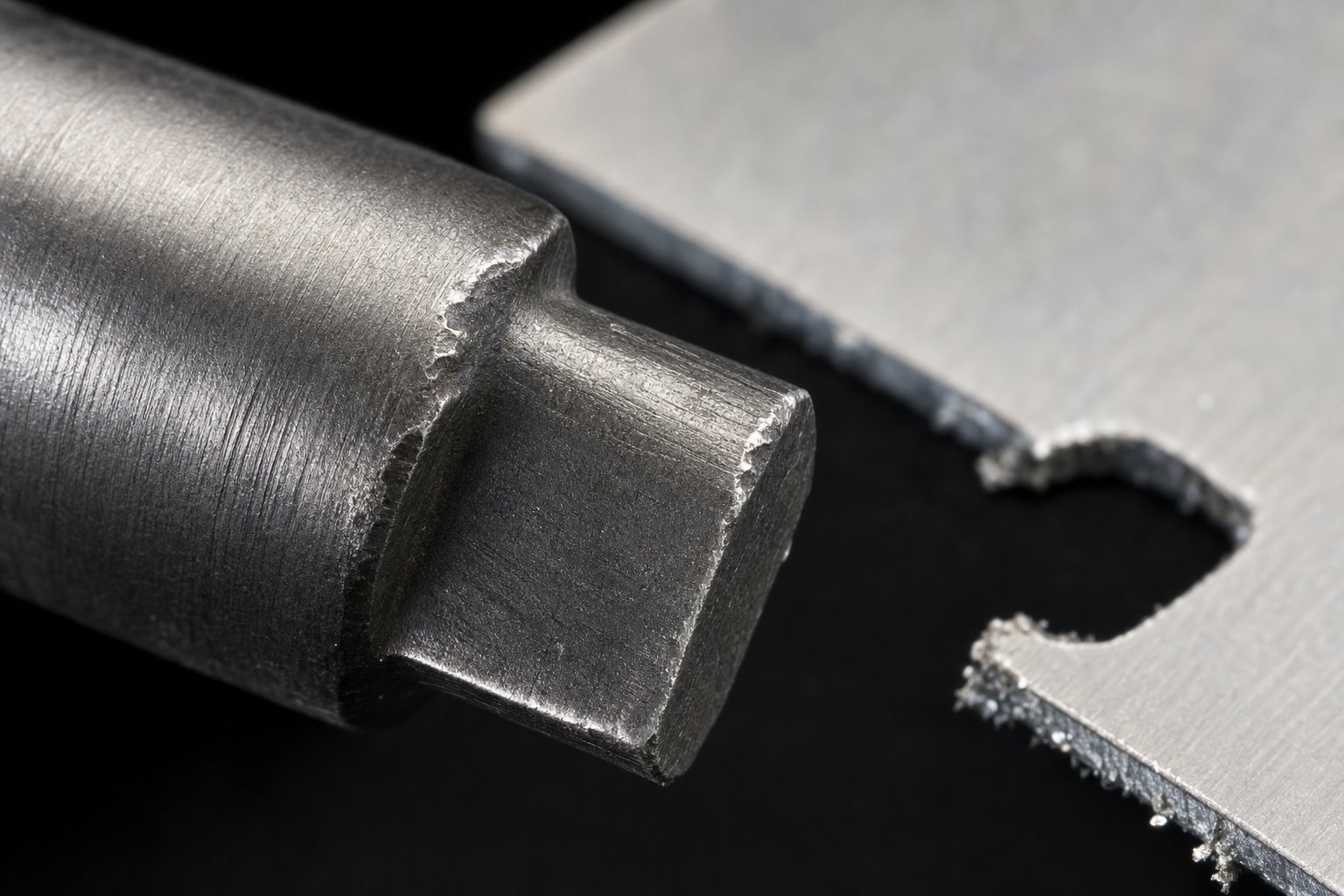
Bypass notch punches and die buttons wear like any other cutting tool. The difference is that notch wear often goes unmonitored because the notch is not a visible part feature - it is a process feature that disappears with the scrap strip. Over hundreds of thousands of strokes, the notch punch edges dull and the cutting clearance between punch and die button opens up. The result: notch dimensions shrink slightly as rounded punch edges fail to shear material cleanly, and the notch opening ends up smaller than designed.
That dimensional loss may only amount to 0.1 to 0.3 mm per side, but when the original clearance margin was tight, even that small reduction can push a formed feature back into intermittent contact with downstream tooling. As MetalForming Magazine reports, chipping represents the most common failure mechanism when cutting higher-strength materials, and the resulting edge degradation directly reduces the precision of every cut - including bypass notch cuts.
Burr buildup introduces a second layer of risk. Bypass notches burr formation in stamping follows the same mechanics as any shearing operation: material is displaced along the cut edge, and a small raised lip forms on one side of the strip. That burr lip projects into the clearance space the notch was supposed to create. Over long runs, burr height grows as the punch dulls further, progressively reducing effective clearance from the edge inward.
The direction of the burr matters. In a standard punch-through-die configuration, the burr forms on the die side of the strip. If the bypass notch is a positive notch (clearing an upward feature), the burr projects downward and typically does not interfere with the feature it was designed to clear. But if the burr direction aligns with the feature protrusion - which can happen with negative notches or inverted tooling setups - the burr itself becomes a secondary interference surface.
- Root cause: Absence of scheduled notch-punch inspection in the preventive maintenance program, and failure to account for burr direction relative to the clearance corridor during initial design.
- Prevention: Include notch punch sharpening in the same maintenance cycle as forming punches. Track notch dimensions at regular intervals using go/no-go gauges or vision inspection of sample strips. During design, orient the punch and die so that the burr direction faces away from the clearance corridor. When burr direction cannot be oriented favorably, increase the clearance margin by the expected maximum burr height - typically 5 to 10 percent of material thickness for standard cutting clearances. Some shops use an inductive proximity sensor mounted near the notching station to detect strip-height variations caused by excessive burr growth, triggering a maintenance alert before interference occurs.
Pilot Pin Conflicts and Registration Errors
Bypass notches and pilot pins compete for the same limited strip real estate. Pilots require solid, flat material to engage and locate the strip precisely at each station. A bypass notch placed too close to a pilot position can undermine registration in two ways: it removes material that the pilot needs to bear against, or it weakens the zone around the pilot hole so that the pilot deforms the edge of its hole during engagement rather than positively locating the strip.
When registration drifts, every downstream operation shifts with it. Blanking profiles move off-center, hole locations migrate, and formed features no longer align with their intended bypass notch openings at subsequent stations. The original interference problem returns - not because the notch is undersized, but because the strip is no longer positioned where the design assumed it would be.
- Root cause: Notch geometry specified without cross-referencing pilot pin locations and their engagement zones across the full strip progression.
- Prevention: Maintain a minimum distance of at least two material thicknesses (or 2 mm, whichever is greater) between any notch edge and the nearest pilot hole perimeter. During strip layout planning, map pilot engagement zones as exclusion areas that no notch boundary can encroach upon. If spatial constraints force a notch close to a pilot, reinforce the pilot zone with a local carrier tab or relocate the pilot to an uncompromised section of the strip.
Each of these failure modes shares a common thread: they develop gradually and silently during production, rarely announcing themselves until the press stops. Building detection and prevention into both the initial design and the ongoing maintenance program catches degradation early - before it reaches the point of strip jams and emergency repairs. That proactive mindset applies not just to avoiding failures, but to establishing the broader set of best practices that keep bypass notches performing reliably across the full life of the die.
Best Practices for Reliable Bypass Notch Performance
Preventing failure is not the same as achieving consistent, long-term performance. The failure modes discussed above tell you what to avoid. Best practices tell you what to actively build into every die design, every strip layout review, and every maintenance cycle so that bypass notches keep doing their job quietly for the entire life of the tool. The difference between a die that runs 500,000 hits without an interference-related stoppage and one that needs emergency attention at 50,000 hits almost always traces back to how deliberately these practices were followed from day one.
Standardizing Clearance Margins by Material Class
One of the simplest improvements a tooling team can make is to stop recalculating clearance margins from scratch for every new job. Instead, establish standard clearance tables organized by material class, thickness range, and feature type. When you know what is yield strength for a given grade and how that grade behaves in forming, you can assign default margins that reflect real production conditions rather than theoretical minimums.
A practical classification might look like this:
| Material Class | Typical Yield Strength Range | Recommended Bypass Notch Clearance Margin |
|---|---|---|
| Mild steel (CRS, 1008/1010) | 170 - 250 MPa | 0.5 - 1.0 mm per side |
| HSLA / structural steel | 340 - 550 MPa | 1.0 - 1.5 mm per side |
| Advanced high-strength steel (DP, TRIP) | 590 - 980 MPa | 1.5 - 2.0 mm per side |
| Aluminum alloys (5xxx, 6xxx) | 100 - 310 MPa | 1.0 - 1.5 mm per side |
| Stainless steel (301, 304) | 250 - 500 MPa | 1.0 - 1.5 mm per side |
These margins account for the elastic modulus of steel (approximately 200 GPa for carbon and alloy grades) and the lower tensile modulus steel alternatives like aluminum (around 70 GPa), which deflect more under feeding loads and demand wider clearance. Higher yield-strength materials spring back more aggressively, pushing formed features beyond their intended envelope. The yielding point of steel in advanced high-strength grades can shift the effective feature boundary by 0.5 mm or more compared to the punch geometry, which is exactly why those grades need larger margins.
Standardizing does not mean ignoring job-specific variables. It means starting from a proven baseline and adjusting only when the specific geometry demands it - rather than guessing fresh each time. Document the table, update it as production data confirms or refines the values, and make it accessible to every designer on the team.
Coordinating Notch Design With Strip Layout Planning
Bypass notches do not exist in isolation on the strip. They share space with pilot pin holes, carrier bars, tie tabs, lifter contact zones, and pitch notches. Treating the notch as an afterthought - something added after the forming sequence is finalized - almost guarantees conflicts. The better approach integrates bypass notch planning into the strip layout from the very first iteration.
Here are the coordination points that matter most:
- Pilot pin exclusion zones - Map every pilot location first. No bypass notch edge should encroach within two material thicknesses of a pilot hole perimeter. Pilots are the strip's registration backbone, and weakening their surrounding material degrades every downstream operation.
- Carrier bar integrity - Evaluate the carrier cross-section at every notch location. If multiple notches cluster near the same pitch position, their combined removal must still leave enough material to resist feeding forces. Carrier bars that drop below minimum bending resistance need redesign - wider carriers, dual-carrier layouts, or redistribution of notch positions.
- Lifter contact areas - Lifters push upward on the strip to elevate it for indexing. A lifter that pushes into an open notch provides no support. Cross-reference lifter locations against notch positions and ensure solid material sits under every lifter pin.
- Tie bars and flex webs - In strip layouts that use tie bars to connect the part to the carrier, notch placement must not interrupt those connections. A notch that accidentally severs a tie bar releases the part prematurely, causing jams or lost parts in the die.
Documenting notch intent in the die design records is equally important. When a maintenance technician resharpens a notch punch two years later, they need to know why that notch exists, what feature it clears, and what the critical dimensions are. Without that documentation, well-meaning maintenance can inadvertently reduce a notch below its required clearance - restoring the very interference the notch was designed to prevent. As Art Hedrick emphasizes, every detail on the print must be clearly defined with no room for interpretation, and bypass notch specifications deserve the same rigor as any forming dimension.
Include these details on the die print or in a supplementary maintenance document for each bypass notch:
- The station and feature the notch clears
- Minimum acceptable notch dimensions (width, depth, feed-direction length)
- Maximum acceptable burr height before resharpening is required
- Punch sharpening interval (in strokes or production hours)
- Burr direction and its relationship to the clearance corridor
Partnering With Experienced Die Solution Providers
For straightforward single-feature clearance problems, an experienced in-house designer handles bypass notch planning without difficulty. The challenge escalates when you are working with complex multi-station progressive dies where dozens of formed features travel through numerous downstream stations, where carrier strength is tight, and where lifters, pilots, and tie bars all compete for the same strip real estate. In those scenarios, the coordination effort multiplies, and design decisions ripple across the entire strip layout.
Engineers facing these design-heavy projects benefit from partnering with providers who specialize in custom progressive die solutions - teams that have solved bypass notch optimization challenges across hundreds of tool builds and understand how notch geometry interacts with die structure, component design, burr control, clearance engineering, and material flow as a unified system. YICHEN's stamping die solutions offer this kind of integrated support, particularly for progressive die projects where multiple strip control features must work together without compromise. Having access to that depth of experience shortens the design cycle, reduces development iterations, and delivers dies that run cleanly from first hit to end of life.
The prevention-by-design philosophy runs through every best practice in this article: standardize your clearance margins, coordinate notch placement with the full strip layout, document your intent for future maintenance, and bring in specialized expertise when the complexity exceeds routine work. Bypass notches prevent interference in a stamping die only when they are designed deliberately, validated thoroughly, and maintained consistently. Get those three elements right, and the strip feeds cleanly, the press keeps running, and interference becomes a problem you solved at the drawing board rather than one you fight on the production floor.
Frequently Asked Questions About Bypass Notches in Stamping Dies
1. What is the purpose of bypass notches in a progressive stamping die?
Bypass notches are deliberate material removals cut into the carrier strip that create clearance corridors for previously formed features - such as lances, drawn cups, embossments, and bent tabs - to pass through downstream stations without colliding with punches, die blocks, strippers, or lifters. They eliminate strip jams, part damage, and tool breakage by addressing collision risks at the design stage rather than reacting to interference on the production floor.
2. What is the difference between positive and negative bypass notches?
A positive bypass notch removes strip material on the same side as the formed feature's protrusion direction, typically clearing upward-facing features like lances or bent tabs against stripper plates. A negative bypass notch removes material on the opposite side, creating clearance below the strip plane for downward-facing features like drawn cups or extruded bosses. Complex parts with multi-directional forming often require both types within the same strip layout, and engineers must verify that combined material removal does not compromise carrier strip integrity.
3. How do you determine the correct size for a bypass notch?
Notch sizing starts with the formed feature's three-dimensional envelope - including its post-springback geometry, not the nominal punch dimensions. Add a clearance margin of 0.5 to 2.0 mm per side depending on material class, press speed, and feed system precision. The notch must be long enough in the feed direction to fully contain the feature footprint plus leading and trailing margins. Critically, the notch width should never exceed 60 to 70 percent of the carrier bar width at any cross-section to maintain strip feeding reliability.
4. What causes bypass notches to fail during production?
The most common failure modes include insufficient clearance that causes intermittent contact at production speed, oversized notches that weaken the carrier and cause misfeeds, progressive punch wear that gradually shrinks notch dimensions over long runs, burr buildup on notch edges that reduces effective clearance, and notch placement that conflicts with pilot pin locations leading to registration errors. Each failure develops gradually and silently, which is why scheduled inspection of notch punch condition and notch dimensions should be part of every preventive maintenance program.
5. When should you use bypass notches instead of strip lifting or station skipping?
Bypass notches are the preferred solution for tall or deeply formed features that must pass through multiple downstream stations, where strip lifting cannot provide sufficient clearance height and station skipping would waste excessive strip material and increase die length. Strip lifting works best for shallow downward features, while station skipping suits single-station interference with modest protrusions. For design-heavy progressive dies with complex interference challenges, providers like YICHEN (https://www.yichen-group.com/stamping-die/) offer custom stamping die solutions that optimize the combination of bypass notches, lifter coordination, and carrier strip planning as an integrated system.


