


What Hot Stamping Dies Are and Why They Matter
When you search for "hot stamping dies," you could be looking at two completely different worlds of manufacturing. One involves crushing automotive steel at 900 degrees Celsius. The other involves pressing delicate gold foil onto a luxury perfume box. Same term, vastly different tooling. Getting them confused during sourcing can cost weeks of engineering time and thousands in misquoted projects.
Hot Stamping Dies Defined
At their core, hot stamping dies are precision-engineered tools that transfer a combination of heat, pressure, and shape to a workpiece. The die serves as the interface between raw material and finished product, controlling how thermal energy and mechanical force interact with the substrate. Whether that substrate is a boron steel blank destined for a car's B-pillar or a sheet of holographic foil landing on premium packaging, the fundamental principle remains the same: a shaped tool applies controlled heat and pressure to permanently alter the target material.
The distinction lies in scale, temperature, material, and purpose. Each hot stamp type demands entirely different die materials, cooling strategies, and maintenance protocols. Understanding which category you are working within is the first step toward extending die life and avoiding premature failure.
Press Hardening Dies vs Foil Stamping Dies
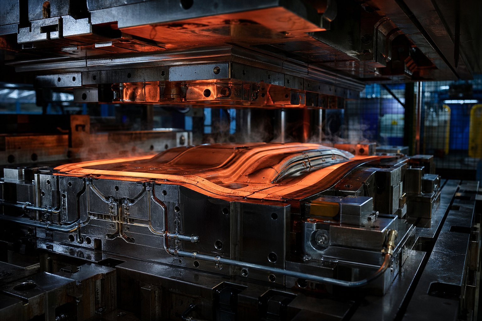
Press hardening stamping dies operate in the automotive and structural metalforming space. They receive steel blanks heated to 900-950 degrees Celsius, simultaneously form them into complex shapes, and quench them at cooling rates exceeding 27 degrees per second to achieve a fully martensitic microstructure with tensile strengths around 1500 MPa. These dies are massive, water-cooled tool steel assemblies that endure extreme thermal cycling every production cycle.
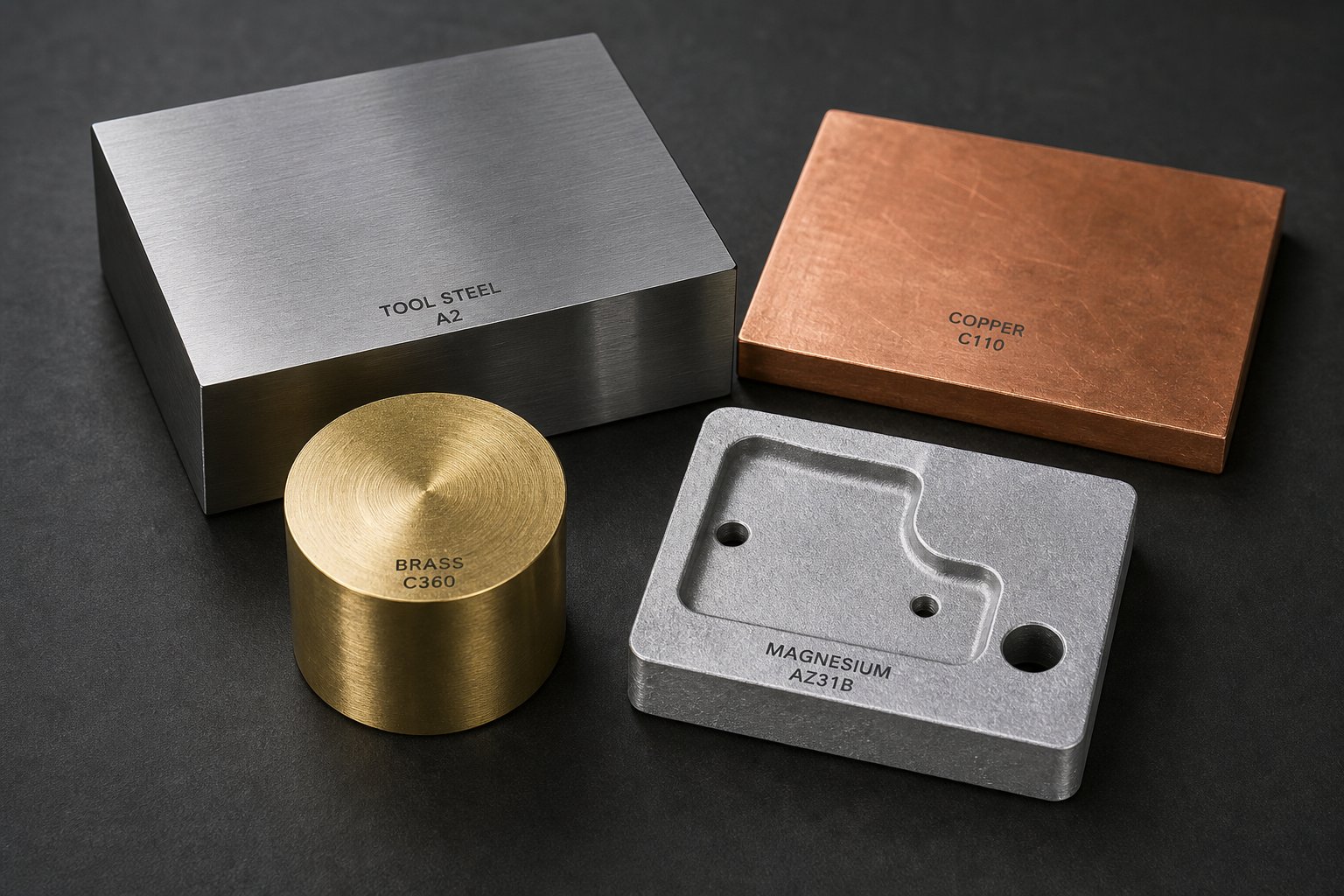
Foil stamping dies, by contrast, operate at much lower temperatures, typically between 100 and 200 degrees Celsius. They use a heated die to activate an adhesive layer on a foil carrier, transferring metallic or pigmented designs onto paper, plastic, leather, or other substrates. The dies themselves are usually made from copper, brass, or magnesium rather than hardened tool steel.
Here is a quick comparison of what separates these two hot stamping type categories:
- Operating temperature: 900-950 degrees Celsius for press hardening vs 100-200 degrees Celsius for foil stamping
- Die material: H11/H13 tool steel vs copper, brass, or magnesium
- Workpiece: Boron steel sheet metal (0.5-2.0 mm thick) vs foil carrier contacting paper, plastic, or leather
- Primary function: Structural forming plus metallurgical quenching vs decorative surface marking
- Cooling system: Internal water channels for rapid heat extraction vs passive or minimal cooling
- Die complexity: Large multi-ton assemblies with conformal cooling vs smaller etched or engraved plates
- Typical die life: Tens of thousands of press cycles vs over one million impressions for quality copper or brass dies
Why the Distinction Matters for Sourcing
Imagine sending an RFQ for "hot stamping dies" to a supplier who specializes in decorative foil tooling when you actually need press hardening dies for an automotive body-in-white program. The quoting engineer would need entirely different information: blank material grade, cooling rate targets, part geometry data, and production volume. Conversely, an automotive toolmaker receiving a request for a copper hot stamp die to mark luxury packaging would likely decline or redirect you entirely.
This confusion is not hypothetical. It happens regularly because both industries use identical terminology while operating in separate engineering ecosystems. The materials, design methodologies, failure modes, and maintenance strategies differ so dramatically that sourcing the wrong supplier type wastes procurement cycles before any tooling work even begins.
This article serves as a unified reference, covering both press hardening and decorative applications so you can identify exactly which category applies to your project, understand how failure occurs in each context, and apply the right lifecycle extension strategies from day one. The sections ahead break down process workflows, material selection, cooling design, and maintenance practices for both worlds of stamping dies.
How the Hot Stamping Process Works Step by Step
The die itself is only one station in a larger production chain, but it is the station where everything either comes together or falls apart. Understanding the full workflow reveals why die design decisions carry so much weight and where premature failure typically originates.
From Heated Blank to Formed Part
In the press hardening process, a flat steel blank, typically 22MnB5 boron steel, enters a roller hearth furnace and heats to over 900 degrees Celsius. At this temperature, the steel transforms into a fully austenitic microstructure, soft enough to form but primed for hardening. The transfer from furnace to press takes roughly 6 to 10 seconds, during which the blank may cool to around 700 degrees Celsius.
Here is where the hot stamping tool takes center stage. The blank lands on the die, the press closes, and two things happen simultaneously: the steel is formed into its final geometry and quenched by the water-cooled die surfaces. Forming must be completed before the blank drops below 420 degrees Celsius. If the quenching rate exceeds 27 degrees Celsius per second, the part achieves nearly 100 percent martensite, yielding tensile strengths around 1500 MPa. Typical cycle times for this stamping hot process range between 10 and 20 seconds depending on material thickness.
After quenching, the press opens and the hardened part is extracted. The die has performed a dual role that no other component in the line can replicate: it shaped the part and extracted heat fast enough to lock in a martensitic microstructure. That dual function is precisely what makes these dies so vulnerable to thermal fatigue over time.
How Foil and Marking Processes Differ
The decorative heat stamp workflow operates on an entirely different scale. A heated die, usually made from copper or brass, is brought to a temperature between 100 and 200 degrees Celsius. A foil carrier is positioned between the die face and the substrate, which could be paper, cardboard, leather, or plastic. When the hot stamp tool presses down, the heat activates the adhesive layer on the foil, bonding the metallic or pigmented design to the surface.
Dwell times are short, often under two seconds, and pressure is measured in far lower ranges than automotive forming. The critical variables here are temperature consistency across the die face, even pressure distribution, and precise alignment. Any variation produces incomplete foil transfer or blurred edges rather than the structural defects seen in press hardening.
Critical Process Parameters Controlled by Die Design
In both applications, the die is not a passive tool. It actively governs the outcome. Die geometry determines material flow and contact area. Thermal mass dictates how quickly the die absorbs or delivers heat. Contact pressure ensures uniform engagement between die and workpiece.
Every decision made during die design, from channel placement to surface finish, ripples through every downstream quality metric including cycle time, dimensional accuracy, microstructure consistency, and ultimately, die longevity itself.
For press hardening, poor thermal management in the hot stamping tool creates uneven quench rates. Some zones cool too slowly, producing bainite or ferrite instead of martensite. Others cool too quickly, generating residual stresses that cause springback. For decorative applications, uneven thermal distribution across the die face creates hot spots that over-cure adhesive in some areas while leaving others unbonded.
These thermal and mechanical interactions are why die material selection and cooling channel design carry such outsized importance. The die is where process intent becomes physical reality, and where most failure modes ultimately originate.
Die Materials and Steel Grade Selection Compared
Material choice is the single most consequential decision in die engineering. It sets the ceiling for thermal performance, wear resistance, and ultimately, how many cycles the die can endure before failure becomes inevitable. Pick the wrong grade for your application and you are fighting physics from day one. Pick the right one and you have a foundation that cooling design, surface treatment, and maintenance can build on.
Tool Steel Grades for Press Hardening Dies
Press hardening dies endure repeated thermal shocks as 900-degree blanks contact their surfaces every cycle. The tool steel must retain hardness at elevated temperatures, resist thermal fatigue cracking, conduct heat efficiently into cooling channels, and absorb impact without catastrophic fracture. Three grades dominate this space: H11, H13, and DIEVAR.
H13 (AISI H13, DIN 1.2344) has been the industry workhorse for decades. It offers solid hot hardness, reasonable toughness at around 15-20 Joules on Charpy V-notch testing, and a thermal conductivity of approximately 24 W/mK. For moderate production volumes and standard part geometries, H13 delivers dependable performance at a cost that most programs can absorb. Its limitations surface under extreme conditions: complex geometries with tight radii, high cycle counts exceeding 100,000 parts, or aggressive cooling requirements that amplify thermal stress.
H11 (DIN 1.2343) shares a similar composition to H13 but with slightly lower vanadium content. This gives it marginally better toughness in some heat treatment conditions, making it a preferred choice in European toolmaking for dies subject to high mechanical loads. The tradeoff is slightly reduced wear resistance compared to H13. In practice, H11 and H13 are often interchangeable for standard press hardening applications, with the final choice depending on regional availability and the toolmaker's heat treatment expertise.
DIEVAR represents a fundamentally different alloy philosophy. Produced through Electro Slag Remelting (ESR), it achieves near-zero inclusions and a homogeneous carbide distribution that eliminates the grain boundary precipitation common in standard H13. The results are measurable: impact toughness exceeding 25 Joules (typically 30-40 J), thermal conductivity around 30 W/mK, and significantly better temper resistance at elevated operating temperatures. That higher conductivity translates directly into faster heat extraction from the blank, which means shorter cycle times or more uniform quenching, depending on how you exploit it.
The cost-per-kilogram for DIEVAR exceeds H13 considerably. But here is the calculation that matters: if a custom metal stamping die made from H13 cracks after 50,000 cycles while a DIEVAR die runs 100,000 cycles with longer maintenance intervals, the total cost of ownership favors the premium material. This is especially true for large, complex dies where a single catastrophic failure means weeks of downtime and six-figure replacement costs.
Selection criteria come down to three factors:
- Production volume: Below 50,000 parts, H13 is often sufficient. Above that threshold, DIEVAR's fatigue resistance pays dividends.
- Part complexity: Tight radii, deep draws, and variable thickness sections create stress concentrations where DIEVAR's superior toughness prevents crack initiation.
- Cooling requirements: When aggressive cooling channel placement is needed close to the die surface, DIEVAR's isotropic properties reduce the risk of cracking between channels.
Non-Ferrous Die Materials for Foil and Logo Stamping
Decorative stamping dies operate at far lower temperatures and pressures, which opens the door to a wider range of materials. Each carries distinct advantages for specific substrates and production scenarios.
A copper stamping die is the premium choice for foil transfer applications. Copper's thermal conductivity, around 385 W/mK, is unmatched among common die materials. This means exceptionally even heat distribution across the die face, which translates into consistent foil adhesion with zero cold spots. Copper reproduces fine detail beautifully and works especially well on plastics and coated papers where precise temperature control prevents substrate damage. The downside is that copper is relatively soft, so it wears faster under high production volumes.
A hot brass stamp offers the best balance between durability and thermal performance for medium-to-high volume decorative work. Brass reaches around 109 W/mK in thermal conductivity, lower than copper but still excellent. Its real advantage is mechanical hardness. A hot brass stamp die holds its edge definition across hundreds of thousands of impressions, making it the go-to material for leather goods, plastics, paper products, and wooden items. For operations running production volumes that would wear out a copper die prematurely, brass delivers consistent quality over a much longer lifespan.
Magnesium dies serve a different purpose entirely. They are inexpensive to produce, lightweight, and quick to manufacture, making them ideal for short runs, prototyping, and applications where the die may be used for a limited campaign. Magnesium excels on greeting cards, book bindings, labels, ribbons, and advertising specialties where run lengths are measured in thousands rather than hundreds of thousands. Detail reproduction is acceptable but does not match copper or brass for very fine artwork.
Aluminum stamping dies occupy a middle ground. They offer better thermal conductivity than brass (around 205 W/mK), lighter weight than steel, and reasonable durability. Aluminum works well for larger die faces where weight reduction matters and for substrates that respond well to the slightly different heat transfer characteristics.
Silicone dies represent a niche option for irregular or curved substrates. They conform to non-flat surfaces, making them suitable for marking cylindrical objects or textured materials. However, they lack the precision edge definition of metal dies and wear quickly under production conditions.
Material Selection Decision Framework
Choosing the right material requires balancing operating conditions, production demands, and budget constraints against each other. The following table consolidates all major die materials into a single reference, covering both press hardening and decorative applications:
| Material | Max Operating Temp | Thermal Conductivity | Typical Application | Relative Cost | Expected Die Life |
|---|---|---|---|---|---|
| H13 Tool Steel | 600+ degrees C | ~24 W/mK | Press hardening, standard automotive | Medium | 50,000-100,000 cycles |
| H11 Tool Steel | 600+ degrees C | ~24 W/mK | Press hardening, high-load applications | Medium | 50,000-100,000 cycles |
| DIEVAR (ESR) | 600+ degrees C | ~30 W/mK | High-volume press hardening, complex geometry | High | 100,000-200,000+ cycles |
| Copper | ~200 degrees C | ~385 W/mK | Fine detail foil stamping, plastics, coated paper | Medium-High | 50,000-250,000 impressions |
| Brass | ~200 degrees C | ~109 W/mK | Medium-high volume foil stamping, leather, paper | Medium | 250,000-1,000,000+ impressions |
| Magnesium | ~180 degrees C | ~156 W/mK | Short runs, prototypes, book bindings, labels | Low | 5,000-50,000 impressions |
| Aluminum | ~200 degrees C | ~205 W/mK | Medium runs, large die faces, lightweight needs | Low-Medium | 25,000-100,000 impressions |
| Silicone | ~180 degrees C | Low | Curved surfaces, irregular substrates | Low | 1,000-10,000 impressions |
A few guiding principles emerge from this comparison. For any custom metal stamping die intended for press hardening, the decision is primarily between H13 and DIEVAR, with the tipping point being production volume and part complexity. For decorative applications, the decision tree splits differently: copper for maximum detail and thermal uniformity, brass for longevity on longer runs, magnesium for cost-effective short campaigns, and aluminum stamping dies when weight or die size becomes a constraint.
Keep in mind that material selection alone does not determine die life. The best tool steel in the world still fails prematurely if cooling channels are poorly routed or surface treatments are neglected. Material sets the upper boundary of performance. Everything else in the die's design and maintenance program determines how close you actually get to that boundary.
Cooling Channel Design Methodology for Hot Stamping Dies
Material sets the ceiling, but cooling channel design determines whether a die actually reaches it. You could build a press hardening die from the finest DIEVAR steel available and still watch it fail prematurely if the internal cooling architecture cannot extract heat uniformly. This is where hot stamp tooling lives or dies, often literally, through thermal fatigue cracks that originate between poorly placed channels and the working surface.
Conventional Drilled Channels vs Conformal Cooling
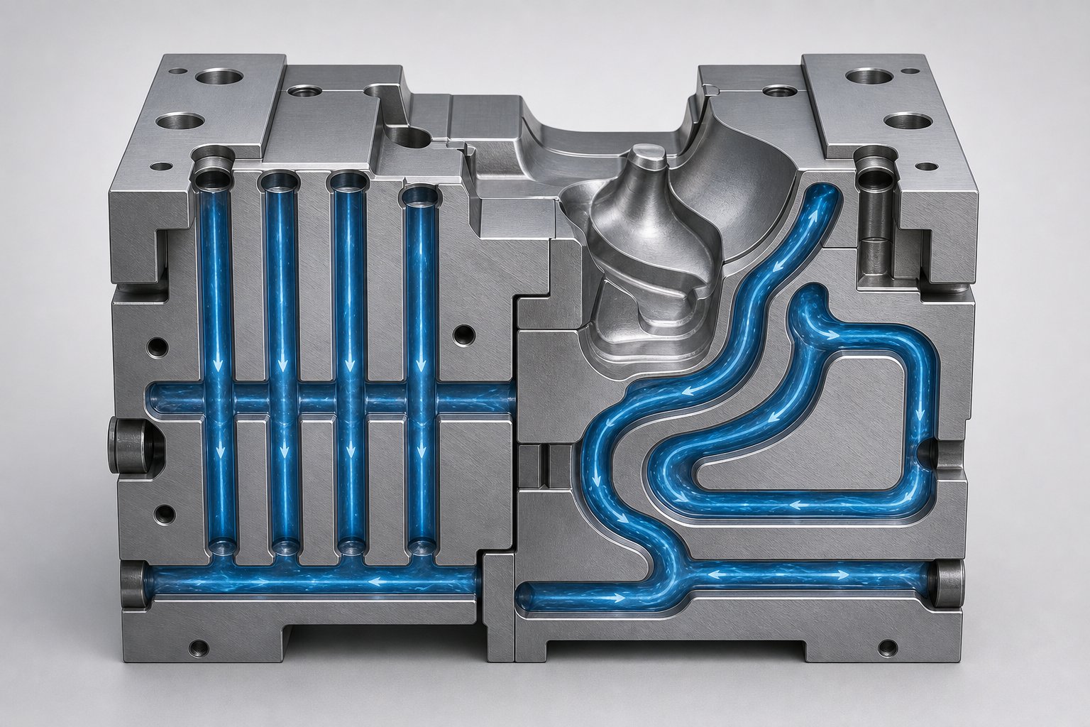
The traditional approach to cooling in a stamping tool and die relies on gun-drilled straight channels. A deep-hole drill bores linear passages through the die block, and cross-connections link them into a circuit. This method is affordable, well-understood, and fast to implement. The toolmaker drills intersecting holes, plugs the unused ends, and connects the active paths to a water manifold. For parts with relatively flat or gently curved geometries, straight channels provide adequate cooling at a fraction of the cost of more advanced alternatives.
The limitation is geometric. Straight lines cannot follow curved surfaces. When part geometry includes deep draws, tight radii, or variable cross-sections, the distance between a drilled channel and the die's working surface varies significantly. Some areas sit close to cooling water and quench rapidly. Others are far away, creating hot spots where heat lingers. A case study on hot stamping tool cooling demonstrated that iterative adjustment of channel position and diameter was required to keep surface temperatures below 200 degrees Celsius across all working areas, even for relatively straightforward beam geometries.
Conformal cooling channels solve this problem by following the contour of the die surface at a consistent depth. The channels curve, angle, and loop in three dimensions to maintain uniform distance from the working face. Manufacturing them requires either additive methods like selective laser melting or a segmented die approach where individual sections are milled with channel grooves, then assembled. Research has shown that conformal channels can reduce production cycle time by up to 25 percent compared to conventional drilled circuits, while also producing more even temperature distributions across the tool surface.
The tradeoff is cost. Additively manufactured die inserts with conformal channels remain expensive for large-scale stamping molds, and the build volumes of most metal printing systems limit insert size. A practical middle ground for many metal stamping tool and die applications is the segmented approach: divide the die into sections, mill cooling paths into mating faces, then bolt or dowel the assembly together. This gives more design freedom than gun drilling while avoiding the full cost of additive manufacturing.
Design Parameters That Drive Performance
Regardless of channel type, four parameters govern cooling effectiveness: diameter, spacing, depth-to-surface distance, and flow rate. These interact with each other in ways that demand careful balancing. Bring channels closer to the surface and you improve heat extraction, but you also reduce the structural steel between the channel and the die face, increasing the risk of thermal fatigue cracking. Widen the channels and you move more water volume, but you weaken the die body and limit how closely adjacent channels can be spaced.
Experienced toolmakers follow a set of design rules that balance thermal performance against structural durability:
- Channel diameter typically ranges from 8 to 12 mm for automotive press hardening dies, scaled to die size and available coolant flow.
- Spacing between adjacent channels should fall between 3D and 5D (three to five times the channel diameter) to maintain structural integrity while achieving reasonable temperature uniformity.
- Depth from the die surface to the channel centerline is generally held between 2D and 3D. Closer placement improves cooling but accelerates cracking between the surface and channel wall.
- Coolant flow velocity should exceed 1 m/s in all channels to ensure turbulent flow, which dramatically improves heat transfer compared to laminar conditions.
- Parallel channel circuits must be balanced so that no single path carries significantly more or less flow than its neighbors, preventing localized hot spots from uneven cooling.
- Maximum permissible surface temperature after quenching should remain below 200 degrees Celsius to ensure sufficient quench rate for full martensitic transformation.
These guidelines from conformal cooling channel research and production practice represent starting points. Final parameters are validated through thermal simulation and, ideally, confirmed with thermographic measurement during tryout runs.
Impact on Cycle Time and Part Quality
Cooling channel placement directly controls quench rate uniformity, and quench rate uniformity determines whether the finished part achieves consistent mechanical properties throughout. When all areas of the die surface sit within the target temperature range, every region of the blank cools at a rate exceeding 27 K/s, and the resulting microstructure is uniformly martensitic. Production data from validated hot stamping tool cooling systems confirm that properly designed channels yield parts with Vickers hardness consistently in the 400 to 550 HV range and tensile strengths between 1300 and 1650 MPa.
Poor cooling design produces the opposite. Hot spots, areas where the die surface exceeds 200 degrees Celsius, quench too slowly. The blank in those zones may form bainite or ferrite instead of martensite, creating soft spots with inconsistent hardness. These soft zones are invisible to the naked eye but show up as dimensional instability after laser trimming, or worse, as structural weakness in crash performance. Springback increases because the part shrinks unevenly as different regions cool at different rates, locking in residual stresses that release when the part is trimmed or assembled.
Cycle time also suffers directly. If the cooling system cannot extract heat fast enough, the press must dwell longer at the bottom of stroke to complete the quench. Every additional second of dwell time reduces throughput and increases cost per part. Conversely, a well-designed channel system with uniform temperature distribution allows the shortest possible quench time while still meeting metallurgical targets, pulling maximum productivity from the press line.
The gap between a good cooling design and a great one often comes down to simulation, which is exactly where the next layer of die engineering methodology picks up.
Surface Treatments and Protective Coatings Explained
Cooling channels manage bulk heat extraction, but the die surface itself bears the brunt of every forming cycle. It contacts oxide-scaled blanks at extreme temperatures, endures sliding friction as hot stamping metal flows across its face, and absorbs thermal shock each time a new part enters. Without surface protection, even premium tool steels erode, crack, and degrade far sooner than their base material properties would suggest. Surface treatments and coatings extend die life by hardening the contact zone, reducing friction, and blocking the chemical reactions that accelerate wear.
Nitriding and Its Role in Die Longevity
Nitriding is a diffusion-based hardening process that introduces nitrogen atoms into the die surface at relatively low temperatures, typically around 950 degrees Fahrenheit (510 degrees Celsius). Unlike coatings that sit on top of the substrate, nitriding forms a metallurgical bond within the steel itself. Nitrogen reacts with alloying elements like chromium, vanadium, and molybdenum already present in the tool steel, forming hard nitride compounds such as CrN directly within the surface layer. The result is a hardened case that exceeds 58 HRC in surface hardness without any measurable dimensional change to the die.
Two primary methods dominate. Gas nitriding uses an ammonia-rich atmosphere at controlled temperatures over extended dwell times. Plasma nitriding, also called ion nitriding, uses a glow discharge in a nitrogen-enriched low-pressure atmosphere to accelerate nitrogen diffusion. In plasma nitriding, a voltage applied between the die component and the furnace wall generates high ionization around the part, bombarding active nitrogen into the surface more efficiently than gas methods allow.
Typical case depths range from 0.0006 inches (15 microns) to 0.0035 inches (roughly 90 microns), depending on application requirements and the intended service interval before re-treatment. Research on H-13 stamp dies treated with plasma nitriding demonstrated that surface hardness increased from 589 HV to over 1130 HV, effectively doubling the substrate hardness. This hardened layer directly combats adhesive wear caused by oxide scale that forms on heated blanks during press hardening. When a 900-degree boron steel blank contacts the die, its surface oxide layer acts like fine abrasive grit. The nitrided case resists this abrasion far better than untreated tool steel, slowing the progressive material loss that eventually degrades die geometry.
One important consideration: nitriding preserves existing surface conditions. A well-prepared metal stamp die surface emerges from the process with its geometry intact, but any pre-existing defects like poor radii or tool marks are preserved as well. Surface preparation before nitriding matters as much as the treatment itself.
PVD and CVD Coatings for Extreme Conditions
Where nitriding modifies the substrate from within, physical vapor deposition (PVD) and chemical vapor deposition (CVD) add distinct coating layers on top of the die surface. These thin-film coatings, typically between 1 and 5 microns thick, provide a barrier between the tool steel and the hostile forming environment. They reduce friction, resist oxidation, and protect against thermal fatigue cracking that propagates under cyclic thermal loading.
The most common PVD coatings for stamp dies in hot forming applications include:
- CrN (chromium nitride): Provides chemical and heat resistance with a low coefficient of friction around 0.5, good oxidation resistance, and thickness typically ranging from 1 to 4 microns. CrN oxidizes at approximately 700 degrees Celsius, making it suitable for moderate-temperature applications but limiting in full press hardening conditions.
- TiAlN (titanium aluminum nitride): Incorporates aluminum to form a protective Al2O3 layer at high temperatures, which inhibits further oxygen diffusion into the coating. AlTiN-based coatings remain stable up to approximately 900 degrees Celsius before oxidation begins, making them better suited for press hardening environments.
- AlCrN (aluminum chromium nitride): Offers excellent oxidation resistance at elevated temperatures by forming stable oxide layers. Industrial trials show that AlCrN-based coatings deliver wear rates in the 10-9 mm3N-1m-1 range, orders of magnitude better than uncoated tool steel surfaces.
PVD processes operate at relatively low temperatures, around 350 to 450 degrees Celsius, which means they cause minimal distortion to the finished die. This makes recoating practical after the initial coating wears through. A typical recoating interval depends on production volume and the severity of the forming operation, but many shops plan for stripping and recoating every 20,000 to 50,000 cycles for press hardening stamp dies.
CVD coatings, by contrast, deposit at much higher temperatures, approximately 1925 degrees Fahrenheit (1050 degrees Celsius). This elevated processing temperature can affect substrate hardness and dimensions, limiting CVD primarily to applications where the die can undergo full re-heat treatment after coating. The advantage is superior adhesion and the ability to deposit thicker, more complex coating architectures that PVD cannot replicate.
A powerful approach combines both methods in a duplex treatment: plasma nitriding followed by PVD coating. The nitrided layer provides a hard, intermediate support zone between the soft substrate and the hard but thin PVD film. Research demonstrates that this duplex approach on H-13 steel yields hardness values five to six times greater than untreated H-13 and wear resistance two to three times better than nitriding alone. The plasma nitride layer reduces stress gradients between substrate and coating, which significantly improves adhesion and load-bearing capacity under the thermal cycling conditions that hot stamping metal forming imposes.
Selecting the Right Treatment for Your Application
Matching a surface treatment to a specific metal stamp die application requires weighing four variables: die material, operating temperature, production volume, and the substrate being formed.
The metallurgical principle driving selection is straightforward. At temperatures exceeding 900 degrees Celsius, oxide scale forms rapidly on heated blanks. That scale is hard, abrasive, and chemically reactive. Every forming stroke drags scale across the die surface, generating both adhesive and abrasive wear simultaneously. Surface treatments must address both mechanisms: hardness resists abrasion, while low-friction coatings reduce adhesive material transfer.
For press hardening dies operating in direct contact with austenitized blanks, the thermal threshold of the surface treatment becomes the deciding factor. CrN alone may not survive full-temperature press hardening because its oxidation limit of 700 degrees Celsius falls below the blank contact temperature. AlTiN or AlCrN coatings push that limit to 900 degrees Celsius, covering the working range. Duplex treatments (nitriding plus PVD) offer the best overall performance because they protect at multiple scales: the nitrided zone handles substrate support and crack resistance while the PVD layer manages surface friction and oxidation.
For decorative stamp dies operating at 100 to 200 degrees Celsius, the calculations shift entirely. Thermal fatigue is not the primary concern. Instead, wear from repeated contact with foil carriers, paper fibers, or plastic substrates gradually rounds sharp edges and degrades detail. Hard chrome plating was the traditional answer, but many operations are shifting toward nitriding or thin PVD films for longer intervals between maintenance.
The following table compares available treatment options across the critical selection parameters:
| Treatment Type | Method | Max Service Temp | Typical Thickness/Depth | Expected Life Improvement | Cost Tier | Best For |
|---|---|---|---|---|---|---|
| Gas Nitriding | Diffusion | ~500 degrees C (substrate-limited) | 15-90 microns case depth | 2x wear life vs untreated | Low-Medium | General die hardening, moderate production volumes |
| Plasma Nitriding | Diffusion (ion bombardment) | ~500 degrees C (substrate-limited) | 50-200 microns case depth | 2-3x wear life vs untreated | Medium | Precision dies requiring zero distortion, selective treatment |
| PVD CrN | Physical vapor deposition | ~700 degrees C | 1-4 microns | 3-5x wear life vs untreated | Medium | Moderate-temp forming, die casting, low-friction needs |
| PVD TiAlN/AlTiN | Physical vapor deposition | ~900 degrees C | 2-4 microns | 4-6x wear life vs untreated | Medium-High | Press hardening, high-temperature forming |
| PVD AlCrN | Physical vapor deposition | ~900 degrees C | 2-5 microns | 5-8x wear life vs untreated | High | Severe press hardening, maximum oxidation resistance |
| Duplex (PN + PVD) | Nitriding followed by PVD | ~900 degrees C | 50-200 microns PN + 2-4 microns PVD | 6-10x wear life vs untreated | High | High-volume press hardening, maximum die longevity |
| CVD | Chemical vapor deposition | ~1000+ degrees C | 5-15 microns | 5-8x wear life vs untreated | High | Extreme conditions, dies that allow re-heat treatment |
Production volume drives the economic calculation. A die running 10,000 cycles may not justify the cost of duplex treatment, and a simple nitriding pass provides adequate protection. A die expected to produce 150,000 parts, however, almost certainly benefits from the upfront investment in AlTiN or AlCrN coating over a nitrided base, because each recoating cycle costs far less than premature die replacement.
Surface treatment is the last line of defense before contact with the workpiece. But defense alone does not prevent failure. Understanding how dies actually degrade over time, recognizing the early signatures of each failure mode, and responding with the right maintenance action at the right interval is what ultimately separates a die that reaches its full potential from one that fails early.
Applications Across Industries from Automotive to Fashion
Die materials, cooling strategies, and surface treatments only matter in the context of what the die actually produces. The range of applications for hot stamping dies spans from crash-critical vehicle structures weighing several kilograms to delicate gold foil monograms on a leather handbag. Each industry demands a distinct combination of die precision, thermal control, and durability, and understanding these application-specific requirements helps explain why certain failure modes dominate in one sector but barely register in another.
Automotive Structural Components
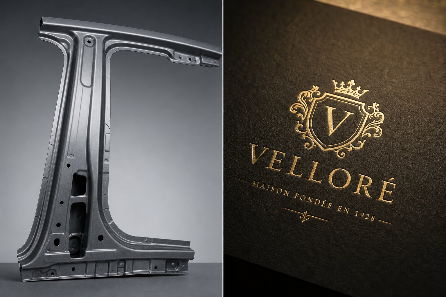
Press hardening dies produce the strongest structural components in modern vehicles. B-pillars, door intrusion beams, bumper reinforcements, roof rails, and tunnel reinforcements all rely on dies that simultaneously form and quench boron steel blanks into ultra-high-strength parts. These components must resist cabin intrusion during crashes while weighing as little as possible, a dual demand that only press hardening satisfies at production scale.
An emerging evolution in this space is Tailored Tempering, also called partial press hardening. Instead of quenching the entire part uniformly, SoftZone tools feature two or more distinct die zones separated by insulation plates. One section is water-cooled to produce fully martensitic, high-strength material. The other is actively heated to approximately 550 degrees Celsius, allowing the blank to cool slowly in that region and retain higher ductility. The result is a single part with hard zones for intrusion resistance alongside soft zones engineered to absorb crash energy through controlled deformation. This approach eliminates the need to weld separate sheet materials together, producing monolithic components with precisely tailored mechanical properties in a single forming step.
For die engineers, Tailored Tempering introduces additional complexity. The die must manage two competing thermal regimes simultaneously, which intensifies thermal gradients at the boundary between heated and cooled zones. These gradients accelerate fatigue cracking at the insulation interface, making material selection and cooling design even more critical.
Packaging, Fashion, and Consumer Goods
The decorative side of hot stamping serves industries where visual impact and brand perception drive purchasing decisions. Hot stamp foil application transforms ordinary packaging into premium shelf presence. Luxury perfume boxes, wine labels, cosmetic compacts, and high-end chocolate packaging all rely on heated dies pressing metallic or holographic foil onto substrates with pinpoint accuracy.
Hot stamping for fashion extends this further into leather goods, handbags, belts, wallets, and shoe accessories. Here, die detail requirements shift. A hot stamp logo on a leather clutch must reproduce fine serif fonts and intricate brand marks at sub-millimeter resolution without scorching the substrate. Die surface finish becomes paramount because any tooling imperfection transfers directly as a visible defect on a product that consumers inspect at arm's length.
Substrate compatibility governs die temperature and dwell time selection. Paper and cardboard tolerate slightly higher temperatures and longer contact. Plastics demand precise thermal control to avoid melting or warping. Leather requires careful balancing to achieve clean foil adhesion without burning surface fibers. Textiles, the most challenging substrate, need even pressure distribution across irregular weave textures. Each material pairing demands specific die temperature settings, and hot stamping for fashion applications often requires custom testing runs before production begins to dial in these parameters.
Electronics and Industrial Marking
Beyond automotive structures and luxury goods, hot stamping dies serve a broad industrial marking role. Electronic device manufacturers use them to apply brand logos, certification marks, and decorative finishes onto plastic housings and enclosures. Appliance manufacturers mark serial numbers and regulatory symbols onto metal chassis. Medical device companies stamp lot codes onto polymer housings where ink-based methods risk contamination or poor adhesion.
A hot stamp for plastic housings must deliver consistent results across thousands of units without substrate deformation. Consumer electronics casings are often thin-walled and heat-sensitive, meaning the die temperature window between achieving clean foil transfer and causing surface damage can be narrow. Industrial hot stamp for plastic applications also demand tight registration accuracy, since logos and marks must align precisely with molded features on the housing.
Each of these industries carries specific requirements that shape die design and maintenance planning:
- Registration accuracy: Electronics marking often requires placement within 0.1 mm to align with molded features, dictating rigid fixturing and precise die alignment systems.
- Substrate sensitivity: Thin-walled plastics and coated papers have narrow thermal tolerance windows, requiring dies with exceptionally uniform surface temperature.
- Production speed: Packaging lines may run at 100+ impressions per minute, demanding dies that maintain thermal stability across rapid cycling without degradation.
- Detail resolution: Fashion and luxury applications require sub-millimeter edge definition for a hot stamp logo, favoring copper or brass dies with mirror-polished surfaces.
- Durability expectations: Industrial marking lines running millions of cycles per year need dies that resist edge rounding and maintain consistent impression depth over extended campaigns.
What connects all these applications is a shared reality: the die must perform consistently, cycle after cycle, under conditions that actively work to degrade it. Whether thermal fatigue cracks a press hardening die or edge wear rounds a foil stamping die's fine detail, the root cause traces back to how well the die was designed for its specific thermal and mechanical environment. Predicting these interactions before they become production problems is exactly what drives the growing role of simulation in die engineering.
CAE Simulation and Thermal Management in Die Design
Physical tryout used to be the only way to verify whether a hot press stamp die would perform as intended. Engineers built the tool, ran trial parts, discovered hot spots or cracking, then modified the steel and tried again. Each iteration consumed weeks and tens of thousands of dollars. Computer-aided engineering simulation has fundamentally changed this calculus by letting engineers identify failure risks digitally, before any steel is cut.
Thermal Simulation for Cooling Channel Placement
Finite element analysis models the heat transfer between a hot blank and the die body, mapping temperature distribution across every surface after multiple consecutive press cycles. The simulation is iterative: it runs the thermal stamping cycle repeatedly until the die reaches a steady-state condition where temperature differences between successive cycles fall below a convergence threshold, typically around 2 degrees Celsius between iterations.
This approach reveals exactly where hot spots will develop before a single channel is drilled. In a documented case involving automotive door beam dies, researchers used a two-stage simulation workflow. The first stage ran approximate thermomechanical analysis in forming simulation software to pre-select channel arrangements and diameters. The second stage performed full coupled thermal-flow CFD analysis on the 3D die model, solving both heat conduction through the tool steel and coolant flow through the channels simultaneously. The result confirmed that maximum surface temperatures stayed below 200 degrees Celsius across all working areas, with most surfaces falling in the 120 to 150 degree range. Thermovision camera measurements on the physical tool later confirmed these predictions within 10 degrees Celsius of the simulated values.
What makes this methodology powerful is the speed of the first-stage analysis. Preparing and running the approximate thermal model for a die and punch takes roughly 8 hours, allowing engineers to test multiple channel configurations quickly. The full CFD analysis, while far more accurate, requires approximately 80 hours per die and punch combination and consumes significant computational resources. The practical workflow combines both: rapid iteration on channel layout in the first stage, then detailed validation of the final design in the second.
Forming Simulation and Die Geometry Optimization
Thermal simulation addresses cooling, but the die must also form the part correctly. Crash-forming and deep-drawing simulations predict how material flows across die surfaces, where thinning exceeds safe limits, and how much springback the part will exhibit after the press opens. These predictions directly inform die geometry compensation, adjustments to the die surface that pre-distort the tool shape so the sprung part lands on its nominal dimensions.
The strategy follows a systematic sequence described by simulation practitioners as measure, mitigate, control, and compensate. First, simulation measures the expected springback magnitude and type, whether it manifests as twist, flattening, side-wall curl, or oil canning. Then, process modifications like coining radii or ironing flanges mitigate the worst distortions. Finally, the die surfaces receive compensation vectors that pre-bend them opposite to the predicted springback direction.
This loop is iterative. Each geometry correction changes material flow, which changes strain distribution, which changes springback. CAE-driven development typically reduces physical tryout iterations by 30 to 50 percent compared to traditional design-build-fix approaches. For advanced high-strength steels and the stamp hot stamping process, where forming windows are narrower and springback is more severe, simulation is not optional. These materials simply cannot be reliably formed without virtual validation first.
Process-Parameter Relationships
Die design choices do not operate in isolation. Channel placement affects quench rate, which affects cycle time. Cycle time affects die surface temperature at the start of the next stroke, which affects thermal fatigue accumulation. Forming geometry affects contact pressure distribution, which affects local heat transfer, which circles back to quench uniformity. Every parameter connects to every other.
Optimizing one parameter in isolation, whether cycle time, part quality, or tool longevity, without accounting for its effect on the other two inevitably produces a die that fails earlier, runs slower, or makes defective parts.
Simulation makes these tradeoffs visible before they become production problems. Engineers can test whether a 1-second reduction in cycle time pushes any die zone above its thermal fatigue threshold. They can verify whether a geometry compensation that improves dimensional accuracy also creates a stress concentration that shortens tool life. This interconnected view transforms die engineering from sequential decision-making into system-level optimization.
The payoff extends beyond individual die performance. Fewer physical tryout loops mean faster time-to-production. More accurate first-shot tools mean less rework and fewer emergency die repairs during launch. And a die designed with simulation data backing every decision starts production life closer to its maximum potential, giving maintenance teams a healthier baseline from which to manage inevitable degradation.
Maintenance, Failure Modes, and Die Lifecycle Management
Simulation and smart design give a die the best possible starting point, but every tool degrades from the moment it enters production. The difference between a die that reaches its designed service life and one that fails catastrophically at 25 percent of expected lifespan almost always comes down to what happens between press strokes: the inspections performed, the warning signs recognized, and the maintenance decisions made before small problems compound into expensive failures.
Preventive Maintenance Schedules and Inspection Points
Preventive maintenance for hot stamping dies is scheduled work that controls normal wear before it becomes scrap, downtime, or die damage. The key distinction here matters: maintenance preserves condition, while repair restores something already broken. When shops conflate the two, they end up firefighting instead of preventing, and the hidden costs of emergency repair, including quality spills, expedited shipments, idle press time, and debugging, accumulate far beyond what planned maintenance would have cost.
For press hardening dies, routine maintenance centers on four critical systems:
- Cooling channel flushing: Scale and mineral deposits build up inside water channels with every production shift. Left unchecked, these deposits restrict flow, create localized hot spots, and accelerate the very thermal fatigue cracking they were designed to prevent. Regular flushing with weak acid solvents or high-pressure water maintains full flow capacity. After flushing, channels should be air-dried with compressed air and coated with an oil-based protective layer if the die will sit offline for any duration.
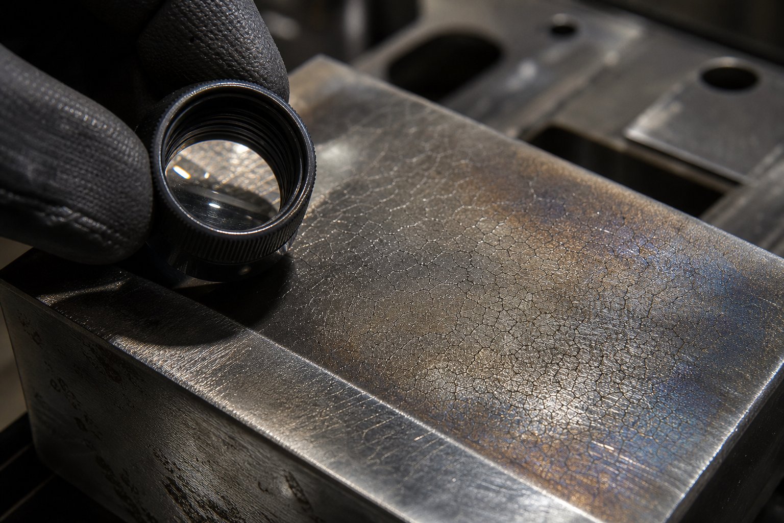
- Surface inspection for thermal fatigue cracking: Visual and dimensional checks of the forming surfaces reveal the earliest signs of heat checking, the fine network of surface cracks that eventually propagate into structural failures. Die radii, areas near cooling channel walls, and zones with the highest contact pressure deserve priority attention.
- Dimensional verification of critical forming surfaces: As thermal cycling accumulates, die surfaces can undergo subtle plastic deformation or localized material loss that shifts part dimensions outside tolerance. Regular measurement against baseline data catches drift before it reaches the part rejection threshold.
- Lubrication and water system checks: Confirm that all coolant connections, flow sensors, and distribution manifolds deliver consistent volume to every channel circuit. Unbalanced flow between parallel channels creates the same temperature non-uniformity that poor initial design would.
For hot foil stamping dies and printing dies used in decorative applications, maintenance priorities shift toward edge sharpness verification, die face cleanliness, and temperature controller calibration. Foil stamping dies accumulate adhesive residue, substrate fibers, and oxidation products on their working surfaces. These deposits degrade impression quality gradually, making regular cleaning with appropriate solvents essential between runs.
Production volume dictates inspection intervals. A press hardening die running 500 parts per shift demands daily surface checks and weekly channel verification. A foil stamping die producing 50,000 impressions per day may need cleaning after every shift but only dimensional checks weekly. The right schedule follows actual wear evidence and stroke counts rather than arbitrary calendar intervals. As industry practitioners recommend, building maintenance around baseline measurements like downtime frequency, first-part capability, and throughput variability produces more reliable intervals than guesswork.
Common Failure Modes and Root Cause Identification
Hot stamping dies fail in predictable patterns, and each pattern leaves characteristic signatures that point toward root cause. Recognizing these signatures early is what separates a scheduled maintenance stop from an emergency press shutdown.
A 2025 failure analysis of a hot-stamping die insert used for manufacturing an automobile A-pillar demonstrated one of the most insidious failure mechanisms. The die, made from 4Cr5Mo2V steel (equivalent to H13-class), cracked after only 50,000 cycles, just 25 percent of its expected 200,000-cycle service life. The root cause was stress-induced corrosion in the cooling channels. When the die sat offline for approximately one month without channel protection, humidity corroded the inner walls. During subsequent production, cyclic mechanical and thermal stresses combined with this corroded surface to initiate cracks that propagated from the channel walls toward the working surface. The research confirmed that more than 90 percent of failed hot-stamping dies start cracking from cooling channel inner walls.
This finding underscores a reality many shops overlook: failure often begins in areas you cannot see during routine visual inspection. The most dangerous failure modes in press hardening dies include:
- Thermal fatigue cracking: Fine surface cracks (heat checking) that develop from repeated heating and cooling cycles. Signature: network of shallow cracks visible under magnification on die radii and high-contact zones, progressing to deeper individual cracks over time.
- Stress-induced corrosion cracking: Cracks originating from cooling channel inner walls where residual tensile stress and corrosive moisture interact. Signature: water leakage from die body, unexplained loss of cooling performance, or visible cracks emerging near channel locations on the working surface.
- Adhesive wear from oxide scale: Material transfer from the heated blank's oxide layer onto the die surface, building up deposits that score subsequent parts. Signature: progressive surface roughening, material buildup on die faces, scratching on formed parts.
- Erosive wear at material flow points: Localized material loss where hot steel flows across die surfaces under high contact pressure, particularly at draw radii and entry points. Signature: visible grooves or channels worn into the die surface along material flow paths, increasing part thinning at those locations.
- Gross fracture from overloading: Catastrophic cracking through the die body caused by excessive press tonnage, misalignment, or loss of support. Signature: sudden, large-scale crack often accompanied by audible failure, press tonnage spike, or visible die displacement.
- Plastic deformation: Permanent shape change of the die surface under repeated high-temperature mechanical loading. Signature: gradual dimensional drift in parts without visible cracking, die surfaces showing compression marks or mushrooming at contact points.
For foil stamping dies and printing dies, failure modes are less dramatic but equally consequential for quality. Edge rounding from cumulative impressions degrades fine detail. Surface pitting from adhesive residue creates voids in foil transfer. Thermal distortion from uneven heating warps the die face, producing inconsistent impression depth across the design.
The research on the A-pillar die also revealed a metallurgical degradation mechanism that compounds all other failures. During service, carbides gradually precipitate and coarsen at grain boundaries in the tool steel, weakening the bonds between grains. Impact energy near the cooling channels dropped to just 15 to 39 percent of the core material's toughness, meaning the steel near the channels had become significantly more brittle than the die's bulk material. This embrittlement makes cracking easier to initiate and faster to propagate, effectively shortening the die's tolerance for any additional stress concentrations.
Refurbishment vs Replacement Decision Criteria
When inspection reveals degradation, the question becomes whether to refurbish or replace. This is fundamentally an economic decision, but one that must account for more than just the immediate repair invoice.
Refurbishment options for press hardening dies include re-nitriding worn surfaces, re-machining forming areas that have undergone plastic deformation, welding repairs for localized cracking, and stripping and recoating PVD-treated surfaces. Each restores the die to a functional state, but none returns it to day-one condition. Welded zones typically have lower hardness than the parent material. Re-machined surfaces alter die geometry slightly. Re-nitrided layers may differ in depth or uniformity from the original treatment.
The right framework uses cost-per-part analysis that captures four factors:
- Cumulative maintenance cost: Total spending on all prior maintenance and refurbishment for this die, including materials, labor, and any contracted services.
- Downtime cost: Press idle time during each maintenance event, multiplied by the hourly cost of lost production. Emergency repairs typically carry 3 to 5 times the downtime cost of planned maintenance because they interrupt running production.
- Quality degradation: If refurbished dies produce parts with higher scrap rates, wider dimensional variation, or more rework, those costs must be captured per part produced.
- Remaining productive life: How many additional parts can the refurbished die reasonably produce before the next intervention? If each refurbishment cycle yields fewer parts before the next repair, the trajectory is clear.
A practical decision threshold: when cumulative maintenance and repair costs exceed 50 to 60 percent of new die cost, and each successive refurbishment delivers fewer parts before the next failure, replacement becomes the economically sound choice. The A-pillar failure study reinforces this point. A die that cracks at 25 percent of its expected life due to preventable corrosion could potentially be welded and returned to service, but the underlying grain boundary embrittlement near the cooling channels remains. Without stress relief annealing and channel reconditioning, the repaired die is likely to fail again on a similar timeline.
For hot foil stamping dies, the calculus is simpler because tooling costs are lower. A worn copper or brass die that no longer reproduces fine detail cleanly is almost always more economical to replace outright than to attempt re-engraving or re-etching, since the labor cost of rework often approaches the cost of a new die manufactured from fresh material.
The researchers behind the A-pillar die study proposed four specific precautions that apply broadly to any press hardening tool entering storage or extended downtime: clean channels with weak acid solvent or high-pressure water, air-dry with compressed air, coat inner surfaces with oil-based rust inhibitor, and perform stress relief annealing to reduce dislocation density accumulated during production cycling. These steps cost a fraction of a replacement die but directly address the two factors, corrosion and embrittlement, responsible for the most common premature failures.
Tracking maintenance history per die, including hit counts, inspection findings, and repair actions taken, transforms these decisions from gut feelings into data-driven choices. When the records show accelerating failure frequency or diminishing return from each refurbishment, the answer becomes clear before the die makes it obvious in the worst possible way: mid-production.
Sourcing Engineered Custom Hot Stamping Dies
Knowing why dies fail and how to extend their life only matters if the die was built right in the first place. A poorly sourced tool, one made from the wrong steel grade, with undersized cooling channels, or without proper simulation validation, starts its lifecycle already compromised. For industrial buyers, the supplier selection process is where die longevity either begins or gets undermined before the first production stroke.
What to Evaluate in a Custom Die Supplier
Not every shop advertising custom stamping dies has the depth to deliver press hardening tooling or precision foil stamping dies at the quality level discussed throughout this article. The gap between a competent supplier and a risky one often shows up in capabilities that are invisible on a price quote but obvious during production ramp-up.
Vertically integrated suppliers, those controlling design, machining, heat treatment, and assembly under one roof, reduce coordination risk and improve quality control by eliminating handoffs between separate vendors. When the team that designed the cooling channels also machines them and validates flow rates on the finished die, accountability stays centralized and problems get caught earlier.
Here are the key evaluation criteria buyers should assess when qualifying a hot stamp die maker:
- In-house design and simulation capability: Can the supplier run thermal FEA and forming simulation to validate channel placement and geometry compensation before cutting steel?
- Material sourcing transparency: Does the supplier specify exact steel grades with mill certifications, or simply quote "tool steel" without traceability?
- Machining capacity: Are they equipped for deep-hole drilling, 5-axis CNC, and EDM for complex die geometries? Can they handle the die sizes your application requires?
- Heat treatment control: Do they operate in-house vacuum or atmosphere furnaces with documented temperature uniformity surveys, or outsource to third parties?
- Surface treatment partnerships: Can they coordinate nitriding and PVD coating through qualified providers with verified process parameters?
- Quality certifications: ISO 9001 as baseline; IATF 16949 for automotive press hardening tooling where PPAP documentation is required.
- Lead time commitments: Realistic timelines backed by capacity planning, not optimistic promises that slip once production begins.
- Maintenance support: Do they offer lifetime tooling maintenance, refurbishment services, and spare part inventory for long-running programs?
A supplier who checks these boxes is one who understands that a custom metal stamp die is not just a block of machined steel. It is an engineered thermal system that must perform reliably across tens or hundreds of thousands of cycles. The best stamping companies treat quality as a cultural foundation rather than a checkbox, engaging early in the design phase and proactively solving problems before they reach the production floor.
Requesting Proposals and Comparing Capabilities
The RFQ process for custom stamping dies works best when buyers provide complete technical context upfront. Vague requests produce vague quotes, and the cheapest number on the page rarely reflects the true cost of ownership once maintenance, downtime, and quality losses are factored in.
When preparing your RFQ package, include:
- 3D CAD data of the part geometry (STEP or IGES format)
- Material specification for the workpiece (grade, thickness, coating if applicable)
- Annual production volume and expected die life target
- Cycle time requirements or constraints
- Quality specifications including dimensional tolerances, surface finish, and metallurgical targets (hardness, microstructure for press hardening)
- Any substrate or foil carrier details for decorative applications, including registration tolerances
When comparing proposals across suppliers, look beyond unit price. Evaluate whether the quote includes simulation validation, first-article inspection with documented data, and clearly specified steel grades with heat treatment parameters. Red flags include suppliers who cannot name the specific tool steel they intend to use, those who skip thermal simulation for press hardening dies, or those who quote unrealistically short lead times without explaining how they will achieve them.
Production volume and part complexity influence supplier selection significantly. High-volume automotive programs demand suppliers with proven press hardening experience, simulation infrastructure, and PPAP capability. Shorter-run decorative work or industrial marking applications may prioritize hot stamp stamping customize flexibility, where a supplier can quickly produce copper or brass dies for test runs and iterate on design without heavy overhead. For buyers also sourcing foil carriers, note that hot stamping foil manufacturers typically operate as separate vendors from die makers, though some full-service suppliers maintain relationships with both.
Getting Started with Engineered Stamping Tooling
For buyers ready to move from research to action, narrowing the supplier field starts with identifying partners who demonstrate the integrated capabilities discussed above. A strong starting point is YICHEN's custom stamping die offering, which provides industrial buyers with an engineered metal-forming tooling solution covering hot stamping, die stamping, and related processes. Their vertically integrated approach to die manufacturing aligns with the qualification criteria outlined here, making them a supplier worth evaluating early in the sourcing cycle.
Beyond any single supplier, the sourcing decision should reflect everything this article has covered: material selection matched to your thermal environment, cooling design validated through simulation, surface treatments appropriate for your production volume, and a maintenance framework that protects the investment over time. A die sourced from a qualified partner, built with the right steel, cooled effectively, and maintained proactively is one that reaches its full designed lifespan rather than failing at a fraction of it. That is the difference between metal stamping dies for sale and engineered tooling built to last.
Frequently Asked Questions About Hot Stamping Dies
1. What is the difference between press hardening dies and foil stamping dies?
Press hardening dies operate at 900-950 degrees Celsius, forming and quenching automotive steel blanks into ultra-high-strength components using water-cooled H11/H13 tool steel. Foil stamping dies work at 100-200 degrees Celsius, transferring decorative metallic or pigmented foil onto substrates like paper, leather, or plastic using copper, brass, or magnesium dies. The two share terminology but differ entirely in materials, scale, cooling requirements, and maintenance protocols.
2. How long do hot stamping dies typically last before replacement?
Die life varies significantly by material and application. Press hardening dies made from H13 tool steel typically last 50,000-100,000 cycles, while premium DIEVAR steel can extend that to 100,000-200,000+ cycles. For decorative applications, brass dies can achieve over 1,000,000 impressions, copper dies reach 50,000-250,000 impressions, and magnesium dies are limited to 5,000-50,000 impressions. Proper cooling design, surface treatments like duplex nitriding plus PVD coatings, and preventive maintenance all play critical roles in reaching these upper limits.
3. What causes premature failure in hot stamping dies?
The most common cause is stress-induced corrosion cracking originating from cooling channel inner walls, accounting for over 90 percent of failures in press hardening dies. Other failure modes include thermal fatigue cracking from repeated heating and cooling cycles, adhesive wear from oxide scale on heated blanks, erosive wear at material flow points, and plastic deformation under sustained high-temperature loading. Studies show that dies left offline without channel protection are especially vulnerable, as humidity corrodes inner walls and combines with cyclic stress to initiate cracks.
4. What are conformal cooling channels and when are they worth the investment?
Conformal cooling channels follow the contour of the die surface at a consistent depth, unlike conventional straight-drilled channels that are limited to linear paths. They are manufactured through additive methods like selective laser melting or segmented die construction. Research shows conformal channels can reduce cycle time by up to 25 percent and produce more uniform temperature distributions. They are worth the investment for complex part geometries with deep draws or tight radii where conventional drilling cannot maintain consistent surface-to-channel distance, and for high-volume programs where cycle time savings offset the higher tooling cost.
5. How do I choose the right surface treatment for a hot stamping die?
Selection depends on operating temperature, production volume, and substrate. For press hardening dies contacting blanks above 900 degrees Celsius, AlTiN or AlCrN PVD coatings provide oxidation resistance at working temperatures. Duplex treatments combining plasma nitriding with PVD offer the best longevity, delivering 6-10x wear life improvement over untreated steel. For moderate-temperature applications, CrN coatings work well below 700 degrees Celsius. Lower-volume programs may only require nitriding at 2x life improvement. The economic tipping point favors premium coatings when production exceeds 50,000 cycles, as recoating costs far less than premature die replacement. Suppliers like YICHEN (https://www.yichen-group.com/stamping-die/) can advise on optimal treatment selection based on specific application parameters.


