


What Is Dies Stamping and How It Works
Every metal bracket in your car, every connector in your phone, and every housing on your kitchen appliance started as flat sheet metal. The process that transforms it into a finished shape at scale? Dies stamping.
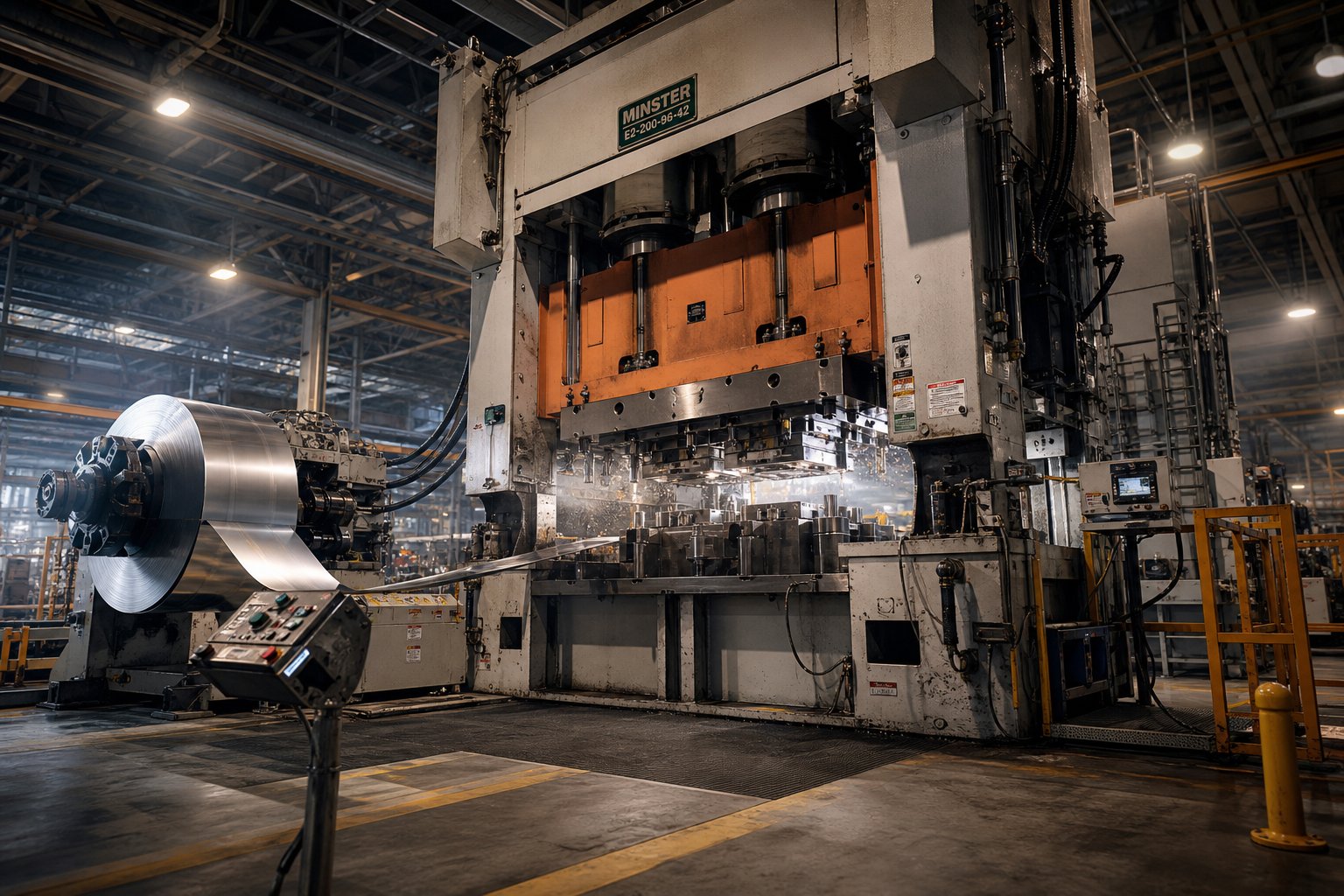
Dies stamping is a cold-forming manufacturing process in which a precision tool called a stamping die cuts, bends, or shapes sheet metal into repeatable parts inside a mechanical or servo press.
What Are Stamping Dies and Why They Matter
So what is a die in manufacturing? It is a custom-engineered tool built to survive thousands or even millions of press cycles while holding tight tolerances on every single hit. Stamping dies contain hardened tool steel or carbide sections that perform cutting, forming, or both operations simultaneously. Unlike general fixtures, these tools must balance accuracy, wear life, and press efficiency under extreme repetitive loads.
What is a stamping operation in practical terms? Imagine flat coil stock feeding into a press at hundreds of strokes per minute, each stroke producing a finished or near-finished component. That consistency is what makes this process the backbone of automotive, electronics, and appliance manufacturing. A single design decision made during die development ripples forward into part quality, scrap rates, and per-piece cost for the entire production run.
How Dies Stamping Fits Into Modern Manufacturing
Understanding what is dies in manufacturing context means recognizing that the die itself is the single largest lever controlling both quality and economics. The tooling investment is upfront, but once a stamping die is validated, it produces uniform parts at a fraction of the cost of machining or fabrication alternatives.
This resource covers the full lifecycle of stamping dies, from type selection and process mechanics through modern simulation-driven design, material choices, quality control, maintenance strategy, and supplier evaluation. Whether you are specifying your first progressive die or optimizing an existing line, each decision in that chain either saves or costs you thousands per run. The chapters ahead break down exactly where those leverage points are and how to act on them.
Types of Stamping Dies and When to Use Each
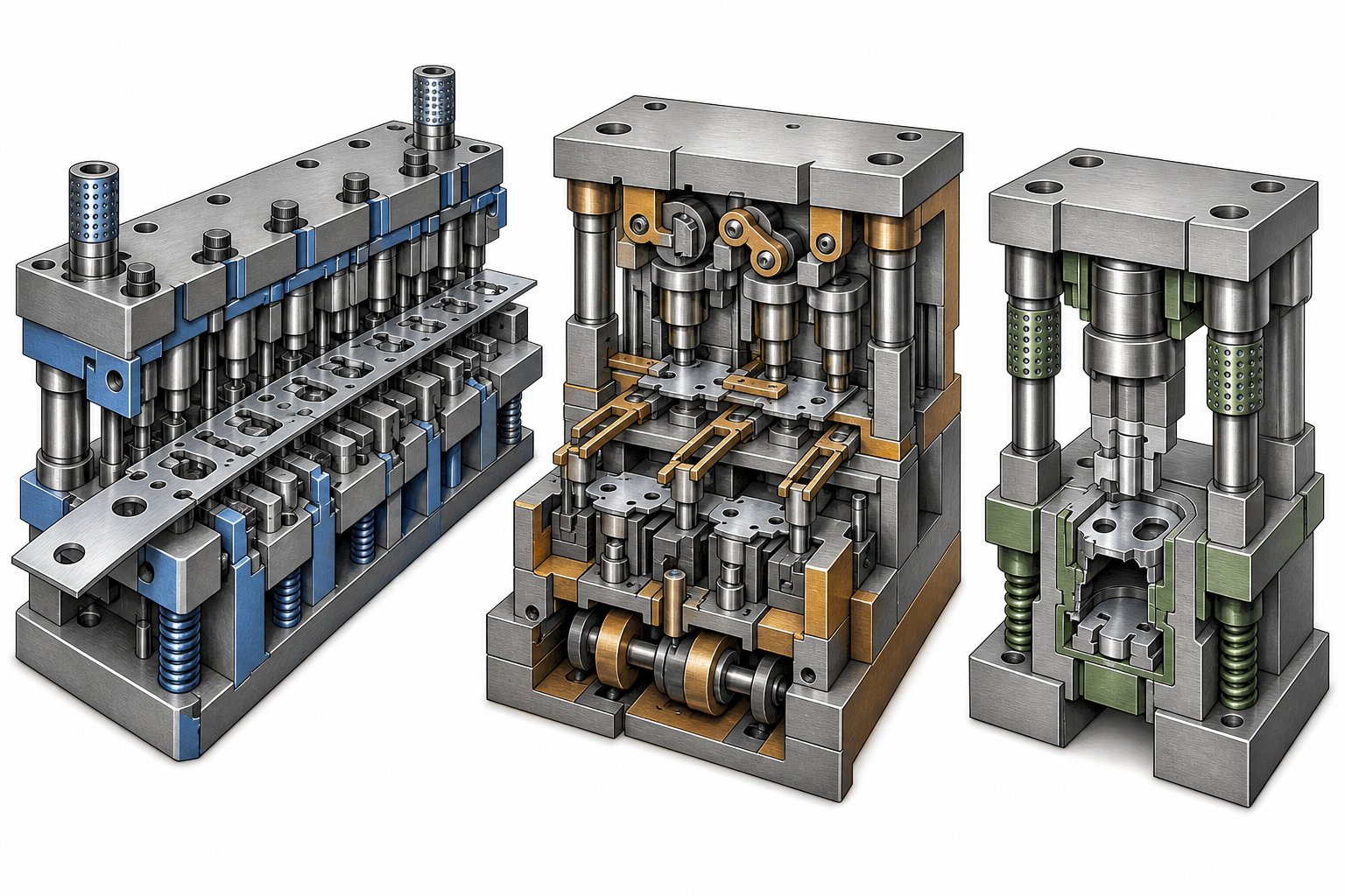
Choosing the right die type is one of those decisions that compounds over every production cycle. Pick a progressive die where a transfer setup belongs, and you will fight part geometry issues for the life of the tool. Pick a compound die where volume demands continuous output, and throughput suffers. The three primary types of stamping dies each solve a different manufacturing problem, and understanding their tradeoffs is what separates cost-effective tooling from expensive mistakes.
Progressive Dies for High-Volume Continuous Production
Progressive metal stamping dies feed coil stock through a series of stations inside a single die set, performing one or more operations at each stop. The strip advances by a fixed pitch with every press stroke, and a finished part drops off the end. Imagine an assembly line compressed into one tool block running at 200-plus strokes per minute.
Station sequencing is where the engineering really matters. Each stage of tooling must be ordered so that earlier operations do not interfere with downstream forming or cutting. A poorly sequenced layout means extra stations, which means a longer die, higher tooling cost, and more scrap in the carrier strip. Strip layout optimization directly controls material utilization. Tight nesting and thoughtful carrier design can push utilization above 80%, while a careless layout wastes 30% or more of every coil. For automotive stamping dies producing brackets, connectors, or structural clips, that scrap difference translates to thousands of dollars per production run.
Transfer Dies for Large or Complex Parts
Transfer stamping uses individual blanks moved between stations by mechanical fingers or robots rather than a continuous strip. This approach removes the geometric constraints progressive dies impose. When a part is too large, too deep-drawn, or requires operations from multiple angles, transfer die sets give you the freedom to orient and re-grip the workpiece at each station.
A typical automotive stamping die for structural body panels or large appliance housings relies on transfer stamping because the part simply cannot stay attached to a carrier strip through deep draws or complex flanging. The tradeoff is cycle speed. Transfer systems run slower than progressive setups, but they deliver dimensional accuracy on parts that progressive dies physically cannot produce.
Compound Dies for Precision Flat Parts
Compound dies perform multiple cutting operations in a single stroke. Blanking and piercing happen simultaneously, which means the part is complete in one hit. This makes them ideal for flat sheet metal stamping dies applications like washers, gaskets, shims, and electrical laminations where flatness and edge quality matter more than forming complexity.
Because all forces act at once, compound dies produce parts with tighter concentricity between features than sequential operations can achieve. The limitation is geometry. These tools handle flat profiles well but are not designed for bending or drawing.
| Dimension | Progressive Dies | Transfer Dies | Compound Dies |
|---|---|---|---|
| Part Complexity | Moderate (bends, forms, cuts) | High (deep draws, multi-angle forms) | Low (flat cut profiles only) |
| Production Volume | High to very high (500K+ parts) | Medium to high (50K-500K parts) | Medium (10K-500K parts) |
| Material Utilization | 70-85% with optimized strip layout | 85-95% (pre-cut blanks) | 60-80% (nesting dependent) |
| Tooling Cost Range | High ($50K-$500K+) | Very high ($100K-$1M+) | Moderate ($20K-$150K) |
| Cycle Speed | Fast (100-1,500 SPM) | Moderate (6-40 SPM) | Moderate to fast (60-400 SPM) |
| Typical Applications | Electrical connectors, brackets, clips | Body panels, large housings, deep-drawn parts | Washers, laminations, gaskets |
The right choice depends on part size, geometry, volume, and budget. Progressive dies dominate when you need speed and the part fits within strip constraints. Transfer stamping wins when part geometry or size rules out a continuous strip. Compound dies deliver precision on simpler flat parts at lower tooling cost. Each type serves a purpose, but none of them performs well without matching stage tooling design to the actual material behavior under forming loads, which is exactly where the stamping process itself demands closer attention.
The Stamping Process from Coil to Finished Part
Matching a die type to your part geometry is only half the equation. The other half is understanding what actually happens to the metal during each press stroke and how those forces determine which press you need. The metal stamping process is a tightly choreographed sequence, and every stage imposes specific demands on both the tooling and the machine driving it.
Core Operations in the Stamping Process
When you break down the sheet metal stamping process into discrete steps, you'll notice that each operation does one of two things: it removes material or it reshapes it. Some dies combine both in a single stroke, but the fundamental actions remain the same regardless of die type or press speed.
Here is the typical sequence a part follows from raw coil to finished component:
- Coil feeding and straightening - A decoiler pays out strip stock, and a straightener removes coil set (residual curvature). A servo feeder or mechanical gripper advances the strip by a precise pitch into the die.
- Blanking - The die cuts a flat shape from the strip or separates the workpiece from surrounding material. This is the first shearing operation, and it establishes the outer profile of the part.
- Piercing (punching stamping) - Internal holes, slots, or cutouts are punched through the blank. Piercing uses the same shearing principle as blanking but removes material from within the part boundary rather than around it.
- Forming and bending - The flat blank is shaped into angles, channels, ribs, or other three-dimensional features. Material stays at roughly the same thickness but flows into new geometry under compressive and tensile forces.
- Drawing - For deeper shapes like cups, housings, or shells, the blank is pulled into a die cavity by a punch while a blank holder controls material flow. The sidewalls stretch under tension, making this one of the most demanding operations on both the die and the press.
- Trimming and final separation - Excess flange material, carrier tabs, or flash is trimmed away to produce the finished part outline. The completed part is ejected by air blast, mechanical knockout, or gravity.
Not every part requires all six steps. A simple bracket might only need blanking, piercing, and a single bend. A deep-drawn automotive cup goes through blanking, multiple draw reductions, and final trimming. The stamping manufacturing process adapts its operation count to part complexity, and the die is engineered to execute exactly the right sequence with zero wasted stations.
Press Tonnage and Die-to-Press Matching
Here is where many stamping programs run into trouble. You can build a perfect die, but if it lands in the wrong press, you get short tool life, dimensional drift, or a jam at bottom dead center. The manufacturing stamping process links die design directly to press selection through one critical number: required tonnage.
Tonnage is not a single calculation. It is the sum of every force the press must deliver simultaneously across all active stations. The basic formula for cutting operations looks like this:
Perimeter (in.) x Material Thickness (in.) x Shear Strength (tons) = Required Cutting Tonnage
But that only covers blanking and piercing. A full die stamping press tonnage calculation also includes forming forces, drawing forces, blank holder pressure, spring stripper loads, nitrogen pad pressure, and any cam-driven operations. You add them all together to get the total press requirement. Undersizing the press means insufficient energy at the bottom of the stroke, even if the rated tonnage seems adequate. Oversizing wastes capital and floor space.
Material properties are the other variable that shifts everything. The aluminum stamping process demands lower cutting force than steel, but aluminum's tendency to gall and spring back introduces different challenges. High-strength steels multiply tonnage requirements substantially compared to mild steel at the same thickness and perimeter. Knowing the coil material's shear strength and ultimate tensile strength in PSI is non-negotiable before sizing a press.
Material Flow and Forming Mechanics
During drawing and forming, metal does not simply bend into shape. It flows. The blank holder restrains flange material while the punch forces the center section into the die cavity. Too much restraint causes thinning and splits. Too little allows wrinkles to form as excess material compresses. Controlling that balance is what separates a good stamping process from one that generates scrap.
Servo press technology gives engineers a powerful lever here. Unlike conventional mechanical presses that follow a fixed crank-driven stroke, servo presses use motor-controlled ram motion that can vary speed and dwell time anywhere in the stroke. Research at Ohio State University's Center for Precision Forming demonstrated that variable blank holder force, cushion pulsation, and attach/detach methods on servo presses improved drawability in high-strength steels where constant-force approaches caused fractures.
In practical terms, a servo press can slow the ram just before contact with the blank to reduce impact shock, then accelerate through the non-working portion of the stroke to maintain cycle time. For drawing operations, the ram can pause or reverse slightly mid-stroke to relieve stress and allow material to redistribute. These variable stroke profiles make it possible to form parts that would split or wrinkle in a conventional mechanical press running at constant velocity.
The takeaway for die designers: press selection is not just about tonnage and bed size. It is about matching the forming mechanics of your specific part and material to the motion capabilities of the press. That relationship between die design and press behavior determines whether your simulation results actually translate into production reality, which is exactly what modern CAE-driven workflows aim to predict before any steel is cut.
Modern Die Design Workflow and Simulation
A decade ago, stamping die design meant building a tool, mounting it in a press, and grinding through rounds of physical tryouts until the part came out right. Each iteration burned time, steel, and budget. Modern metal stamping die design flips that sequence. Engineers now resolve forming problems digitally, long before the first block of tool steel hits a CNC machine. The result is fewer tryout loops, faster time-to-production, and tooling that works closer to right the first time.
CAD/CAM Integration in Stamping Die Design
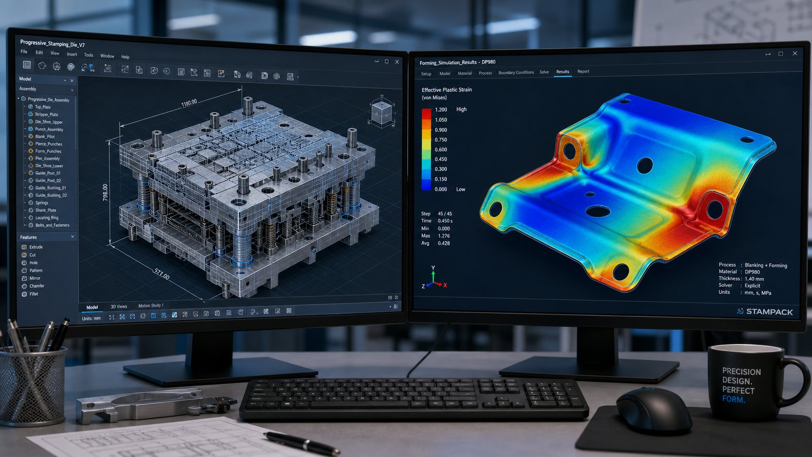
Contemporary stamping design starts in parametric 3D CAD, where the die structure, punch profiles, and strip layout are modeled as a unified assembly. Platforms like SolidWorks, CATIA, and NX host dedicated die-design modules that automate standard components (guide posts, retainers, heel blocks) while letting engineers focus on the forming geometry that actually determines part quality.
The CAD model feeds directly into CAM for CNC programming of die steels, EDM electrodes, and wire-cut profiles. This tight integration eliminates translation errors between design intent and machined reality. In high-volume tool and die manufacturing, that single-model workflow also simplifies revision control. When a customer changes a radius or adds a hole, the modification propagates from the 3D model through toolpaths without manual redrafting.
CAE Simulation for Forming Feasibility
Here is where the real cost savings happen. Finite element analysis (FEA) applied to sheet metal forming, commonly called CAE simulation, lets engineers run a virtual die tryout before any physical tooling exists. The software models material behavior under forming forces and predicts exactly where problems will appear.
What does simulation catch? Three critical defects that account for most physical tryout iterations:
- Thinning and splits - The solver identifies areas where material stretches beyond safe limits and will fracture in production.
- Wrinkling - Excess material compression shows up as buckled zones, particularly in draw walls and flanges where blank holder force is insufficient.
- Springback - The software predicts elastic recovery after the press opens, revealing how far the part deviates from nominal geometry and enabling die compensation before machining.
According to Keysight's engineering analysis, defects often emerge only during first physical trials in die manufacturing, when corrections are both time-consuming and costly. Running those trials digitally eliminates the majority of surprise failures at the press.
Incremental solvers like AutoForm and ProgSim can simulate multi-station progressive dies, automatically adjusting pressure-pad forces and reporting forming tonnage at each station. SolidWorks-based tools such as Logopress ProgSim act as virtual tryout presses, providing formability results including springback and automatic blank development. Setup and simulation for a smaller die can complete in minutes, while larger tools may take a few hours, still far faster and cheaper than a physical tryout cycle.
This simulation-first approach defines how leading die makers operate. YICHEN's stamping die engineering team, for example, runs feasibility analysis and CAE simulation as standard steps before machining begins, validating forming viability and identifying compensation requirements digitally. That workflow means their tooling arrives at the tryout press already close to production-ready rather than starting from a best guess.
Strip Layout Optimization and Material Utilization
Material cost is the largest variable expense in any stamping run, and strip layout is the lever that controls it. The layout defines how blanks are nested within the coil width, how much carrier material connects stations, and where scrap falls away. Small changes in nesting angle or blank orientation can shift material utilization by 5-10%, which translates directly to per-part cost across millions of pieces.
Simulation-driven blank optimization takes this further. Software can flatten the finished 3D part back to its developed blank shape, then automatically test rotation angles and multi-out configurations to find the layout that minimizes coil width and pitch while maintaining formability. Stamping left-hand and right-hand parts together in a two-out layout, or rotating blanks to interlock their profiles, are common metal stamping techniques that simulation validates before any strip is run.
For progressive dies, carrier design is an additional variable. Stretch carriers must be wide enough to feed reliably through each station but narrow enough to avoid wasting material. Simulation allows engineers to design these carriers efficiently, confirming that the strip stays stable under forming loads without consuming unnecessary stock. The balance between production speed and material savings is a compromise, but stamping technology has reached a point where that compromise is quantified digitally rather than discovered on the press floor.
All of this digital validation happens before die steels are selected and ordered. The confidence that simulation provides in the stamping design directly influences the next major decision: which tool steel grades and surface treatments will deliver the required die life for your specific workpiece material and production volume.
Die Material Selection and Tool Steel Grades
Your simulation is validated, your strip layout is optimized, and the forming sequence is locked. The next decision determines how long that tooling actually survives production: which stamping die steel goes into the working sections? Pick a grade that is too soft, and cutting edges dull after a few thousand hits. Pick one that is too hard without adequate toughness, and punches chip under shock loads. Every metal die is a balancing act between hardness, toughness, wear resistance, and cost.
Tool Steel Grades for Stamping Die Construction
Four grades cover the majority of steel stamping dies in production today. Each addresses a different combination of workpiece difficulty and volume demand.
D2 is the workhorse for high-volume blanking and piercing. Its high carbon (1.40-1.60%) and chromium (11.00-13.00%) content deliver exceptional wear resistance at a tempered hardness range of 54-61 HRC. D2 handles stamped sheet metal in mild steel or galvanized coil stock without frequent sharpening. The tradeoff? It is less tough than other grades, so it is not the first choice for applications with heavy shock or lateral loading.
A2 bridges the gap between wear resistance and toughness. With roughly half the chromium of D2 and slightly less carbon, A2 reaches 57-62 HRC while remaining moderately machinable. It excels in trimming, coining, and large blanking operations where some impact resistance is needed alongside good edge retention.
S7 sits at the tough end of the spectrum. Its lower carbon content (0.45-0.55%) and reduced chromium (3.00-3.50%) yield a working hardness of 48-58 HRC with excellent shock absorption. S7 is preferred for forming punches, bending operations, and any sheet metal die section that endures repeated impact rather than pure shearing. When your steel sheet stamping application involves thick gauge material or aggressive bend angles, S7 resists chipping where harder grades would fracture.
DC53 is a modified cold-work steel that improves on D2 by offering roughly twice the toughness at equivalent hardness. It machines more easily in the annealed state and holds sharp edges under the higher loads that advanced high-strength steels (AHSS) impose. For production environments stamping dual-phase or martensitic workpieces, DC53 extends sharpening intervals without the brittleness risks of standard D2.
| Grade | Hardness (HRC) | Toughness | Wear Resistance | Typical Applications | Relative Cost |
|---|---|---|---|---|---|
| D2 | 54-61 | Low-Moderate | Very High | Blanking, piercing, trim dies, slitters | Moderate |
| A2 | 57-62 | Moderate | High | Coining, trimming, large blanking, punches | Moderate |
| S7 | 48-58 | Very High | Moderate | Forming, bending, cold heading, impact tools | Moderate-High |
| DC53 | 60-62 | Moderate-High | Very High | AHSS blanking, high-load punches, precision trim | High |
Carbide and Coating Solutions for Extended Die Life
When even premium tool steels cannot deliver adequate life, carbide inserts and surface coatings step in. Solid carbide or brazed carbide sections offer hardness above 85 HRA and resist abrasive wear from materials like stainless steel or silicon-containing aluminum alloys. They cost significantly more than tool steel and require careful support in the die shoe to prevent fracture, but they pay for themselves on high-volume piercing stations that would otherwise need sharpening every few shifts.
Surface coatings extend the working life of steel substrates without changing core toughness. Traditional PVD coatings like titanium nitride (TiN) and titanium carbonitride (TiCN) add surface hardness and reduce friction on steel-stamping applications. For aluminum stamping dies, however, these ceramic coatings fall short. Aluminum sticks to traditional coatings through localized melting during plastic deformation, a mechanism distinct from the dynamic friction that causes steel galling.
Diamond-like carbon (DLC) coatings solve this problem. Their low coefficient of friction and anti-stick properties prevent aluminum buildup on punch and die surfaces. Field results show that a CrN + DLC multilayer applied to trim inserts eliminated aluminum sticking entirely in one production application, producing over 800,000 parts with no degradation where uncoated tools failed after just 1,000 hits.
Matching Die Materials to Workpiece Properties
The decision framework is straightforward once you map your workpiece to the right material class:
- Mild steel and galvanized coil - D2 or A2 handles most stamped steel applications with standard sharpening intervals. Coatings are optional for moderate volumes.
- AHSS (DP590, DP980, martensitic grades) - DC53 or carbide inserts at cutting stations. TiCN or TiAlN coatings reduce adhesive wear from the harder workpiece.
- Aluminum alloys - S7 or A2 substrates with CrN + DLC coating to combat sticking and abrasion. Boundary lubrication helps in draw stations, but secondary operations like trimming and piercing rely heavily on coating performance.
- Stainless steel - High-chromium tool steels (D2) or carbide inserts paired with TiN or TiCN coatings to resist the abrasive and adhesive wear stainless creates.
Production volume amplifies every material decision. A die running 50,000 parts per year tolerates more frequent sharpening with a lower-cost steel. A die producing millions of stamped steel parts annually justifies carbide inserts and multi-layer coatings because unplanned downtime for maintenance dwarfs the upfront material investment. Matching die material to both workpiece and volume is what separates tooling that lasts from tooling that drains your maintenance budget, and it sets the foundation for a broader question: when does stamping itself become the most economical process compared to other manufacturing options?
When Dies Stamping Is the Right Choice
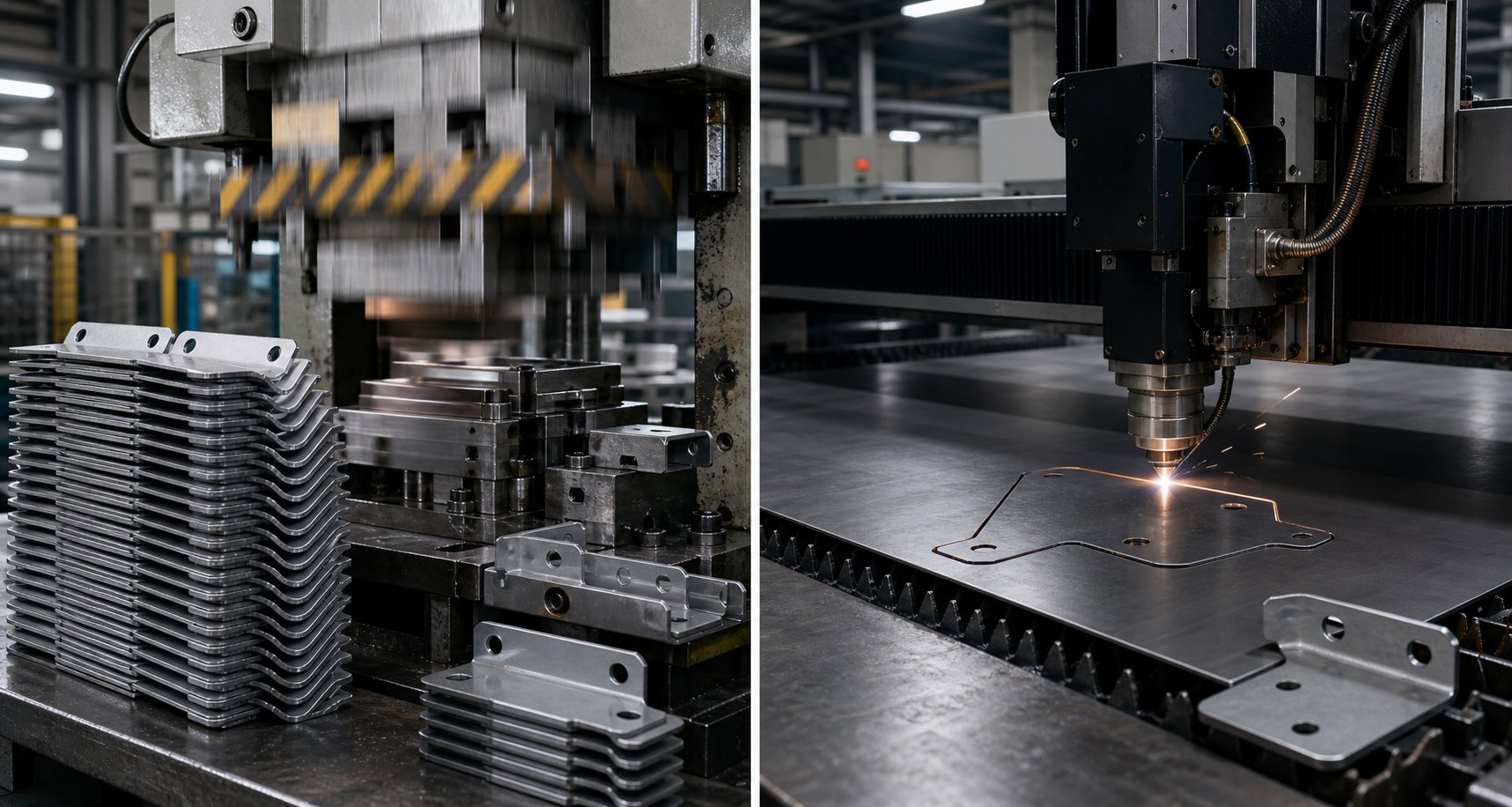
Die material and coating choices keep your tooling alive, but they are irrelevant if stamping is not the right process to begin with. The most expensive mistake in sheet metal stamping is not a chipped punch or a bad strip layout. It is investing in metal stamping tooling for a part that should have stayed on a laser table, or conversely, paying laser-cut prices for thousands of parts that a die could produce in a fraction of the time and cost.
Stamping vs. Alternative Manufacturing Processes
What is metal stamping compared to its alternatives? At its core, it is a high-speed, fixed-tooling process. You pay once for a die, and every subsequent part costs a fraction of what flexible processes charge. Laser cutting, CNC machining, and hydroforming each eliminate that upfront tooling cost but trade it for higher per-piece expenses and slower cycle times.
Laser cutting requires zero tooling and handles design changes instantly. Need to move a hole 2mm? Update the CAD file and cut the next sheet. But the laser must trace every contour sequentially. A complex bracket that takes two minutes to laser cut takes roughly two seconds to stamp. That speed gap becomes a cost gap the moment volumes rise.
CNC machining offers tight tolerances and handles complex 3D geometry without dedicated tooling. It works well for thick parts or features that require material removal rather than forming. But machining wastes material as chips rather than reshaping it, and cycle times scale linearly with part count.
Hydroforming excels at producing deep, complex shapes with uniform wall thickness. It uses fluid pressure instead of matched male-female tooling, which reduces die cost for certain geometries. The tradeoff is slower cycle times and limited applicability to simpler flat or shallow-formed metal parts stamping.
| Dimension | Die Stamping | Laser Cutting | CNC Machining | Hydroforming |
|---|---|---|---|---|
| Ideal Volume Range | 5,000 - millions | 1 - 2,000 | 1 - 5,000 | 500 - 50,000 |
| Per-Part Cost Trend | Drops sharply with volume | Flat regardless of volume | Flat to slightly declining | Moderate decline with volume |
| Geometric Complexity | Moderate to high (forming, drawing) | 2D profiles only (no forming) | Very high (3D machined features) | High (deep uniform shapes) |
| Achievable Tolerances | +/-0.05 - 0.1 mm typical | +/-0.1 - 0.25 mm | +/-0.01 - 0.05 mm | +/-0.1 - 0.5 mm |
| Tooling Investment | $2,000 - $500K+ (die dependent) | $0 | $0 (fixtures only) | Moderate ($10K - $100K) |
Volume Thresholds and Cost-Per-Part Economics
The metal stamping manufacturing process becomes economical at the point where tooling cost, amortized across total parts, drops below the per-piece savings versus alternatives. This is the break-even calculation, and it governs every tooling investment decision.
Consider a real-world example from production cost analysis: a simple steel bracket costs $2.00 per piece via laser cutting with zero tooling. The same bracket costs $0.50 per piece once a $5,000 stamping die exists. The savings of $1.50 per part means break-even arrives at roughly 3,333 parts. Below that number, laser wins on total cost. Above it, stamping saves money on every single additional piece.
For more complex progressive dies, the math shifts but the principle holds. A $12,000 custom die producing parts at $0.45 each versus $3.50 per part via CNC machining breaks even at approximately 3,900 parts. Beyond that threshold, every piece produced delivers $3.05 in savings compared to machining.
The critical insight most buyers miss: you should calculate based on lifetime volume, not just the current order. If you need 2,000 parts now but expect to reorder 2,000 annually for three years, your real volume is 8,000, well above break-even. The metal pressing process rewards long-term thinking because tooling is an asset that keeps producing value on every reorder with no new lead time and no new tooling risk.
A middle ground exists for volumes between 2,000 and 5,000: CNC turret punching uses standard punch tools to nibble part profiles faster than laser for hole-heavy parts, at lower cost than dedicated stamping dies. It bridges the gap between flexible fabrication and committed metal stamping manufacturing.
When to Refurbish vs. Replace Tooling
Tooling economics do not end at break-even. After hundreds of thousands of hits, every die eventually degrades. The question becomes whether to invest in refurbishment or build new tooling. This decision follows a logic similar to the original make-or-buy calculation but with different variables.
Refurbishment makes economic sense when:
- Damage is localized - Surface scratches, worn cutting edges, or individual insert replacement without structural compromise to the die shoe or die sets.
- The die has not exceeded half its expected service life - A well-maintained stamping die can produce hundreds of thousands to millions of parts. If structural integrity remains sound, sharpening and component replacement extend production life significantly.
- Design is stable - If the part design is not changing, restoring existing tooling avoids the lead time and cost of engineering a new die from scratch.
Replacement becomes the better investment when:
- Repair frequency is accelerating - When sharpening intervals shorten and unplanned stops increase, the die is approaching end-of-life. Continuing to run degraded tooling creates hidden costs through declining yield rates, increasing scrap, higher energy consumption, and greater risk of unplanned downtime.
- The base steel is compromised - Corrosion, thermal fatigue cracking, or irreversible deformation of critical surfaces cannot be restored through repair. When the issue originates from the steel itself, replacement is the only effective path.
- Product or material specifications are changing - A die designed for mild steel may not survive a transition to AHSS. If workpiece material is changing or part geometry is being revised, new tooling engineered for updated requirements outperforms a refurbished legacy tool.
- Repair cost approaches 50-60% of new tooling cost - At that ratio, new tooling delivers a full service life ahead while refurbishment offers only a partial extension with ongoing risk.
The conservative approach of running a die until it barely functions often looks like it saves money, but the hidden costs of poor performance erode margins invisibly. Tracking hits-per-sharpening, scrap rates over time, and unplanned downtime incidents gives you the data to make this call objectively rather than waiting for a catastrophic failure.
Whether you are choosing stamping over alternatives or deciding when to reinvest in existing tooling, the underlying question is the same: where does each dollar produce the most parts at the required quality level? That quality dimension, how you measure it and maintain it across millions of cycles, is its own discipline entirely.
Quality Control and Inspection for Stamped Parts
Producing stamped metal parts at hundreds of strokes per minute means nothing if those parts drift out of tolerance halfway through a run. A die that stamps thousands of metal stamping components per hour can just as easily stamp thousands of rejects if no one is watching the process. Quality control in stamping is not an afterthought bolted onto the end of a line. It is a system that starts with how you measure, continues with how you detect problems, and matures into how you prevent them entirely.
Dimensional Inspection and GD&T for Stamped Parts
How do you verify that a metal stamped part meets design intent? The answer depends on how much data you need and how fast you need it.
Traditional inspection uses checking fixtures, pin gauges, feeler gauges, and calipers for quick shop-floor verification. These tools give operators immediate feedback between press runs, but they only check discrete points. You know a hole is in the right place, but you do not see what is happening between measurement points.
Coordinate measuring machines (CMMs) have long been the standard for verifying that a finished stamping meets design criteria at numerous discrete locations. CMMs offer high repeatability and accuracy, and the checking fixtures they require are relatively simple. Portable CMMs have gained ground in stamping plants and die shops because they can move directly to the press where data is needed, combining red-light scanning with touch probes for quick shop-floor reviews.
White-light and blue-light scanning systems represent a significant leap forward. Instead of measuring individual points, these scanners produce full 3D representations of the part surface, allowing engineers to evaluate stampings almost instantaneously against CAD geometry. Tolerances on automotive stamped components now routinely reach +/-0.1 mm, and blue-light LED technology reduces sensitivity to ambient lighting, improving data quality in production environments. These scanners also serve a dual purpose: they can scan existing dies for reengineering or recutting damaged tooling.
Regardless of which technology you use, accurate results depend on following GD&T rules correctly. Stamping examples of common GD&T callouts include profile tolerances on formed surfaces, true position on pierced holes, and flatness requirements on mounting faces. Violating datum setup rules during measurement produces misleading data, so fixture design and part restraint strategy matter as much as the measurement device itself.
Common Stamping Defects and Root Cause Analysis
Every defect in a stamped part traces back to either die condition, material behavior, or process parameters. Often it is an interaction of all three. The challenge is identifying which variable actually changed, because the symptom alone rarely points to a single cause.
Here are the most frequent defects, their typical origins, and corrective actions:
- Burrs (excessive) - Caused by worn or dull cutting edges, improper punch-to-die clearance, or misalignment between upper and lower tool sections. Corrective action: sharpen cutting edges, verify and adjust clearance per material thickness, check guide system for wear.
- Splits and fractures - Result from excessive stretching beyond material forming limits. Root causes include too much wrinkling in the blank holder area restricting metal flow, insufficient lubrication, or material that exceeds its tensile elongation limit. Corrective action: reduce blank holder force, improve lubrication, adjust blank size or shape, or polish draw radius surfaces.
- Wrinkling - Occurs when compressive stresses in unsupported material exceed buckling limits. Too little blank holder pressure, excessive draw depth relative to blank size, or incorrect draw bead geometry all contribute. Corrective action: increase holding force, adjust standoffs or equalizers, add or modify draw beads.
- Springback - Elastic recovery after the punch retracts causes the part to deviate from intended geometry. More pronounced in high-strength steels and aluminum. Corrective action: overbend in the die to compensate, add coining or bottoming steps, or use servo press dwell at bottom dead center.
- Part features out of location - Holes pierced in wrong positions or forms placed inaccurately. Typically caused by incorrect feed pitch, worn or broken pilots, or improper feed release timing rather than die geometry errors. Corrective action: verify feeder calibration, inspect pilot pins for wear, check feed release timing sequence.
- Loss of flatness - Incoming material that is not flat causes pressure pads to fail at holding the strip, resulting in bending in wrong locations and non-conforming geometries. The die itself cannot manufacture flatness into stock that arrives curved. Corrective action: adjust straightener and leveler settings, compensate for coil-set variations between inner and outer diameter.
A critical insight from precision die stamping troubleshooting: variables interact. Splitting can cause wrinkling (loss of sheet tension after a fracture allows material to buckle), and wrinkling can cause splitting (wrinkled material passing over draw beads restricts flow and triggers thinning downstream). Solving one symptom without understanding the interaction often creates a new problem elsewhere in the stamping die components.
SPC and In-Die Monitoring for Process Stability
Spot-checking stamping parts every 100 or 500 hits tells you what already went wrong. Statistical Process Control (SPC) applied to stamping operations tells you what is about to go wrong, giving you time to act before scrap accumulates.
SPC uses control charts (X-bar and R charts) to track dimensional measurements over time and flag when a process drifts toward its tolerance limits. Electronic data collection devices using bushings and transducers allow operators to capture panel dimensions quickly with high repeatability, feeding results directly into databases for statistical analysis and trend tracking.
In-die sensing takes this further by monitoring forming forces and tool behavior in real time, every single stroke. When first implemented, in-die sensing primarily prevented die crashes. Once that foundation was solid, the technology evolved to detect quality problems and ultimately to correct them automatically.
Three levels of in-die monitoring capability exist in modern stamping operations:
- Crash prevention - Sensors detect misfeeds, slug pullback, or foreign objects and stop the press before catastrophic damage occurs. Stripper-level sensors on all four corners detect when the plate fails to close to proper depth, catching trapped slugs within a single stroke.
- Defect detection - Sensors verify hole presence, feature existence, and forming depth. Digital-output proximity sensors flag parts that deviate from pass/fail thresholds. Sophisticated controls can divert bad parts on-the-fly to a scrap bin without stopping the press.
- Closed-loop correction - Analog-output sensors measure bend angles or material thickness with fractional-degree precision. Servomotors adjust forming stations between strokes via driven wedges, bringing parts back into tolerance automatically without operator intervention or press stoppage.
The progression from crash prevention through defect detection to closed-loop correction represents a maturity ladder. Each level builds on the previous one. A stamping operation that masters all three achieves something close to zero-defect production: the process monitors itself, adapts to material variation, and halts only when conditions exceed the system's correction range.
Quality is not static, though. Die condition degrades over millions of hits, and even the best monitoring system cannot compensate for tooling that has worn beyond its adjustment range. That reality leads directly to the question of how you manage a die across its entire production life: when to sharpen, what to replace, and when the tool has reached the end of its useful service.
Die Maintenance and Lifecycle Management
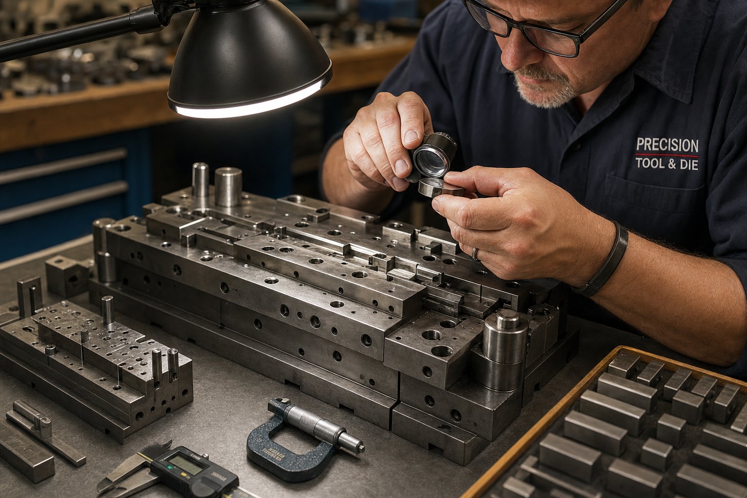
In-die sensors tell you when forming forces shift, but they cannot reverse the wear that caused the shift. Every stamping die is a depreciating asset from its first press stroke. The difference between tooling that delivers millions of reliable hits and tooling that hemorrhages downtime comes down to one discipline: structured lifecycle management. This means managing stamp dies from initial tryout validation through scheduled maintenance intervals and, ultimately, to the end-of-life decision point where refurbishment or replacement becomes unavoidable.
Die Tryout and Validation Before Production
A stamping die fresh off die machining is not production-ready. It is a hypothesis that needs testing. The tryout phase bridges the gap between design intent and real-world performance under actual press tonnage, material behavior, and feeding conditions.
During tryout, engineers install the die tool on a press matching its intended production environment and run trial parts to evaluate forming quality, dimensional accuracy, and process stability. This is not a single pass-fail test. It is an iterative feedback loop: produce trial parts, inspect against drawing tolerances, identify deviations, adjust the die, and run again. Common corrections during tryout include springback compensation, blank holder force adjustment, forming radius modification, trimming line correction, and station timing optimization.
For progressive tooling dies, strip feeding stability is a primary validation target. Engineers verify that pilot pins engage reliably, that the strip advances at correct pitch, and that partially formed features do not interfere with downstream stations. Transfer die tryouts focus on blank positioning accuracy and part handoff between mechanical fingers at each station.
A successful tryout confirms three things: the die produces parts within tolerance, it does so repeatably across consecutive strokes, and no station experiences abnormal loading that would accelerate early wear. Only after these conditions are met does the die enter production, and the maintenance clock starts ticking.
Preventive Maintenance Schedules and Sharpening
Here is where most stamping operations either save or lose thousands per run. The distinction between die maintenance and die repair is critical. As stamping die maintenance expert Art Hedrick explains, true preventive maintenance involves items that need to be addressed regularly, regardless of how well the die was engineered. Replacing springs before they break, sharpening edges before burrs appear, and cleaning debris before it causes a misfeed: that is maintenance. Digging two parts out of a jammed draw die or welding a damaged section after a dowel falls out? That is repair, and it means something upstream failed.
Sharpening intervals are the backbone of any stamping die maintenance program. Cutting edges degrade with every stroke. Waiting until burrs become visible means the tooling has already worn past optimal condition, increasing stripping forces, accelerating slug pulling, and risking punch fracture. Precision manufacturers establish sharpening schedules based on actual stroke count rather than visual inspection alone. For high-speed stainless steel stamping, intervals may be as short as every 50,000-100,000 strokes. Softer materials like mild steel or aluminum allow longer runs between sharpening.
When sharpening, proper technique matters as much as timing. Using the wrong grinding wheel on hardened tool steels like D2 causes heat buildup that softens or cracks the die section. Flood coolant and wheels that break down freely rather than loading up prevent thermal damage during regrinding.
Beyond sharpening, a complete preventive maintenance cycle follows a consistent sequence:
- Clean all debris - Remove slugs, slivers, lubricant buildup, and any foreign material from the die cavity, slug drop holes, and guide surfaces.
- Inspect fasteners and alignment - Check all screws for tightness, verify dowel pins are present and seated, and confirm that no sections have shifted.
- Examine springs and nitrogen cylinders - Replace springs approaching end-of-life cycle before failure. Verify gas pressure in nitrogen systems.
- Inspect cutting edges and forming surfaces - Look for chipping, cracking, galling, or excessive wear patterns. Sharpen or replace as needed.
- Check guide pins and bushings - Measure clearance between guide components. Excessive play indicates lateral movement that degrades punch-to-die alignment.
- Lubricate mating surfaces - Apply appropriate lubricant to wear plates, cam surfaces, and moving components.
- Verify bypass notch condition - Inspect notch geometry for wear that could affect strip feeding reliability.
- Confirm safety devices - Ensure all guards, sensors, and protective features are intact and functional.
- Dry and protect - Remove moisture and apply rust preventive if the die will sit idle before its next run.
The purpose of bypass notches in stamping dies is to control strip registration and allow the material to advance reliably between stations. Both negative and positive bypass notches in sheet metal stamping dies serve this function, but they wear differently. Positive notches (raised features on the strip) experience compressive wear at their contact surfaces, while negative notches (cutouts in the strip) see edge degradation at the transition points. When bypass notch geometry degrades, the strip loses positional accuracy during feeding, which cascades into mislocated features across every downstream station. Monitoring notch wear patterns during scheduled maintenance catches feeding instability before it produces scrap.
End-of-Life Assessment and Refurbishment Options
Every die eventually reaches a point where maintenance no longer restores adequate performance. Recognizing that point before it causes production failures is what separates proactive lifecycle management from reactive firefighting.
Key indicators that metal stamping die sets are approaching end-of-life include:
- Sharpening intervals shortening progressively (for example, dropping from 100,000 strokes to 60,000, then 40,000 between services)
- Dimensional drift that worsens between maintenance cycles despite proper sharpening
- Increasing frequency of unplanned press stops due to misfeeds, slug pulling, or part jams
- Guide system wear creating measurable lateral play that exceeds correction range
- Base steel showing thermal fatigue cracks, corrosion pitting, or irreversible deformation
When these signs appear, the refurbishment-versus-replacement decision depends on where the wear concentrates. If degradation is limited to replaceable inserts, cutting sections, and springs while the die shoe structure remains sound, refurbishment delivers extended production life at a fraction of new tooling cost. Rebuilding guide systems, upgrading to carbide inserts in high-wear stations, and resurfacing forming sections can restore a die to near-original capability.
Replacement becomes the right call when structural integrity is compromised, when the part design has evolved beyond what the existing die geometry can accommodate, or when cumulative repair costs approach 50-60% of new tooling investment. At that threshold, new tooling delivers a full service life ahead with modern materials and coatings, while refurbishment offers only a partial extension with ongoing risk.
Tracking maintenance data over the die's life, hits per sharpening, scrap rates per run, unplanned stops per shift, creates the evidence base for this decision. Without that data, end-of-life decisions become guesswork, and guesswork typically means running degraded tooling too long or replacing functional tooling too early. Neither outcome is economical.
A well-managed die lifecycle does not end at a single tool. It feeds knowledge back into future tooling decisions: which die materials lasted, which stations wore fastest, which maintenance intervals proved optimal. That institutional knowledge becomes especially valuable when evaluating potential die suppliers, because the best partner is the one whose tooling delivers predictable lifecycle performance rather than surprises at the press.
How to Choose a Stamping Die Partner
Lifecycle data tells you what worked and what failed in past tooling. The next question is who builds your next die, and whether their workflow actually prevents the problems your maintenance records documented. Selecting a metal stamping die manufacturer is not a procurement checkbox exercise. It is a technical partnership decision that locks in quality, lead time, and long-term tooling performance for years of production.
Key Evaluation Criteria for Stamping Die Suppliers
A qualified die maker demonstrates capability across the entire tooling workflow, not just machining. When evaluating suppliers, look beyond shop floor photos and assess whether they can engineer a solution, not just cut steel to your print.
Critical capabilities to verify include:
- Engineering and simulation capacity - Does the supplier run CAE forming simulation in-house? A diemaker who validates formability digitally before machining catches springback, thinning, and wrinkling issues that would otherwise surface during costly physical tryouts.
- In-house CNC machining and EDM - Outsourced machining introduces lead time risk and communication gaps. Full in-house capability means tighter control over tolerances and faster iteration.
- Tryout presses on-site - A supplier without tryout capacity ships unvalidated tooling. You want a partner who runs trial parts, measures them, and corrects deviations before the die leaves their facility.
- Inspection equipment - CMMs, optical scanners, and checking fixtures should be standard. Ask what dimensional reports accompany delivered tooling.
- Material and process expertise - The supplier should understand your workpiece material, whether that is mild steel, AHSS, aluminum, or stainless, and select die steels and coatings accordingly.
YICHEN's stamping die division illustrates what a full-service stamping tool and die partner looks like in practice. Their workflow spans feasibility analysis, CAE simulation, precision machining, on-site trial runs, and dimensional inspection, all under one roof. That integrated model eliminates handoff delays between separate engineering firms, machine shops, and tryout houses.
Preparing an Effective Stamping Die RFQ
A vague RFQ gets vague quotes. If you want accurate pricing and realistic timelines from any tool and die making supplier, your request needs to include the information that actually drives tooling cost and complexity.
Essential items to prepare before issuing an RFQ:
- 3D CAD model and 2D drawing with GD&T callouts
- Material specification (grade, thickness, surface condition)
- Annual volume estimate and expected tool life requirement
- Critical tolerances and surface finish requirements
- Secondary operations needed (tapping, welding, plating) that may influence die design
- Target timeline for first article samples and production start
- Quality system requirements (ISO, IATF, PPAP level)
The more complete your package, the fewer assumptions the die and tool supplier makes during quoting. Assumptions create cost surprises later. Suppliers who ask detailed clarifying questions during quoting are typically stronger partners than those who quote immediately without understanding your application.
From Feasibility Study to Production-Ready Tooling
The best tool die making partnerships follow a gated process rather than a single quote-to-delivery transaction. That process looks something like this: feasibility review confirms the part can be stamped as designed, simulation validates forming and identifies needed compensation, detailed die design is reviewed and approved, machining and assembly proceed, tryout produces sample parts for dimensional verification, and final approval releases the die for production shipment.
Each gate gives you a decision point. If simulation reveals a problem, you adjust part geometry or process parameters before machining begins, not after $50,000 in tool steel has been cut. This front-loaded engineering approach is what separates a strategic die maker from a shop that simply machines what you send them and hopes it works.
For sourcing managers moving from research to procurement, the evaluation comes down to a simple question: does this supplier own the full workflow from digital validation through physical proof-out? If any critical step is outsourced or skipped, risk transfers to you. A partner with end-to-end tool and die capability absorbs that risk and delivers validated, production-ready tooling rather than an untested steel assembly that still needs weeks of press-side debugging at your facility.
Frequently Asked Questions About Dies Stamping
1. What is a stamping die and how does it work?
A stamping die is a precision-engineered tool made from hardened tool steel or carbide that cuts, bends, or shapes flat sheet metal into repeatable parts inside a mechanical or servo press. The die contains upper and lower sections that close together during each press stroke, performing operations like blanking, piercing, forming, and drawing. Dies are designed to withstand thousands to millions of press cycles while maintaining tight tolerances on every part produced. The tooling investment is significant upfront, but once validated, a stamping die produces uniform components at a fraction of the cost of machining or fabrication alternatives.
2. What is the difference between progressive dies and transfer dies?
Progressive dies feed continuous coil stock through multiple stations within a single die set, performing one or more operations at each stop as the strip advances by a fixed pitch. They run at high speeds (100-1,500 strokes per minute) and suit smaller parts like connectors, brackets, and clips. Transfer dies use individual blanks moved between separate stations by mechanical fingers or robots. They run slower (6-40 strokes per minute) but handle parts that are too large, too deeply drawn, or require multi-angle operations that cannot stay attached to a carrier strip. Progressive dies optimize for speed and volume; transfer dies optimize for geometric complexity and part size.
3. How do you calculate press tonnage for a stamping die?
Press tonnage calculation requires summing all forces the press must deliver simultaneously. For cutting operations, the formula is: Perimeter (in.) x Material Thickness (in.) x Shear Strength (tons/sq. in.) = Required Cutting Tonnage. However, total tonnage also includes forming forces, drawing forces, blank holder pressure, spring stripper loads, nitrogen pad pressure, and cam-driven operation forces. Material properties significantly affect the result. High-strength steels multiply tonnage requirements compared to mild steel at the same thickness. Undersizing a press causes insufficient energy at bottom dead center, while oversizing wastes capital. Always calculate based on the specific material grade's shear strength and tensile properties.
4. When does stamping become more cost-effective than laser cutting?
Stamping becomes more economical than laser cutting once the tooling investment, amortized across total parts produced, drops below the per-piece savings. For a simple bracket costing $2.00 per piece via laser and $0.50 via stamping with a $5,000 die, break-even occurs at approximately 3,333 parts. More complex progressive dies with higher tooling costs shift the threshold upward but still deliver substantial savings at moderate volumes. The key insight is calculating based on lifetime volume rather than a single order. If you expect annual reorders over several years, your true volume likely exceeds break-even, making stamping the more economical long-term choice. YICHEN offers feasibility analysis to help manufacturers determine whether stamping is the right process for their specific volume and part geometry.
5. How often should stamping dies be sharpened and maintained?
Sharpening intervals depend on workpiece material hardness, die steel grade, and production volume. High-speed stainless steel stamping may require sharpening every 50,000-100,000 strokes, while softer materials like mild steel or aluminum allow longer runs between services. The critical principle is scheduling maintenance based on actual stroke count rather than visual burr inspection, since visible burrs mean the tooling has already worn past optimal condition. A complete preventive maintenance cycle includes cleaning debris, inspecting fasteners and alignment, examining springs and nitrogen cylinders, checking cutting edges, verifying guide pin clearance, lubricating mating surfaces, and confirming bypass notch condition. Proactive scheduling prevents unplanned downtime that costs far more than planned maintenance windows.


