


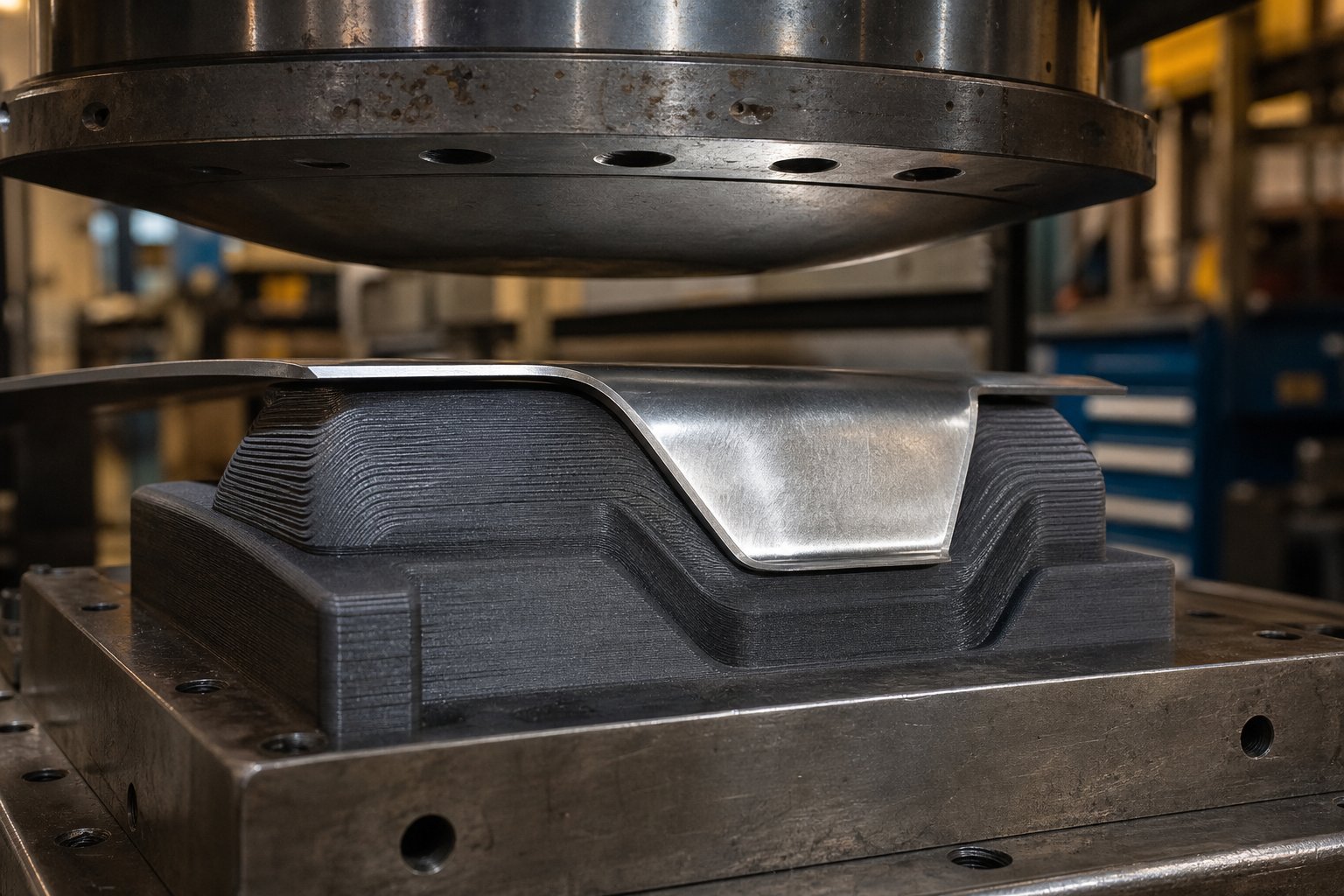
What 3D Printed Stamping Dies Are and Why They Matter
Imagine needing a custom metal forming tool and having it ready in hours instead of weeks. That is the fundamental promise behind a 3D printed stamping die for sheet metal: a punch-and-die set produced through additive manufacturing, either polymer or metal, designed to shape sheet metal parts under press force. Instead of CNC machining a billet of tool steel through multiple setups and programming cycles, you design the die geometry in CAD and send it straight to a printer.
What Is a 3D Printed Stamping Die
A 3D printed stamping die is a forming tool built layer by layer using additive manufacturing technology. It functions the same way a conventional die does: a punch forces sheet metal into or over a die cavity, permanently shaping the workpiece. The difference is fabrication method, not function. These dies can be printed from reinforced polymers for light-duty forming or from sintered metal powders for loads approaching traditional steel tooling. Research at Oakland University has demonstrated that coated 3D-printed die inserts can stamp over 50,000 parts in ultrahigh-strength steel with wear performance comparable to heat-treated D2 tool steel. That result signals this is no longer a novelty approach.
Why This Approach Is Gaining Traction
Traditional die fabrication involves CNC programming, fixturing, multi-setup machining, and often heat treatment. The result is lead times measured in weeks and costs that make iteration painful. A 3D printed die set for prototyping flips that equation. You'll notice the advantages compound quickly: reduced lead time from weeks to days, lower upfront tooling cost, and the ability to iterate a die profile three or four times in the span a single conventional die would take to machine.
When a single design iteration costs days instead of weeks and dollars instead of thousands, engineers stop guessing at die geometry and start testing it. That cost-time compression is what makes printed dies viable as a low cost stamping die alternative, not material strength alone.
This applies across a wide range of users. Hobbyists running arbor presses with thin copper and aluminum benefit from the accessibility. Professional engineers use additive manufacturing metal forming tooling to validate stamped part geometry before committing capital to hardened production dies. Smaller fabrication shops that could never justify traditional tooling costs for short runs can now produce functional dies in-house.
The real question is not whether printed dies work. It is which printing technology, material, and design approach matches your specific forming requirements, a decision that hinges on understanding how each additive process translates into die performance.
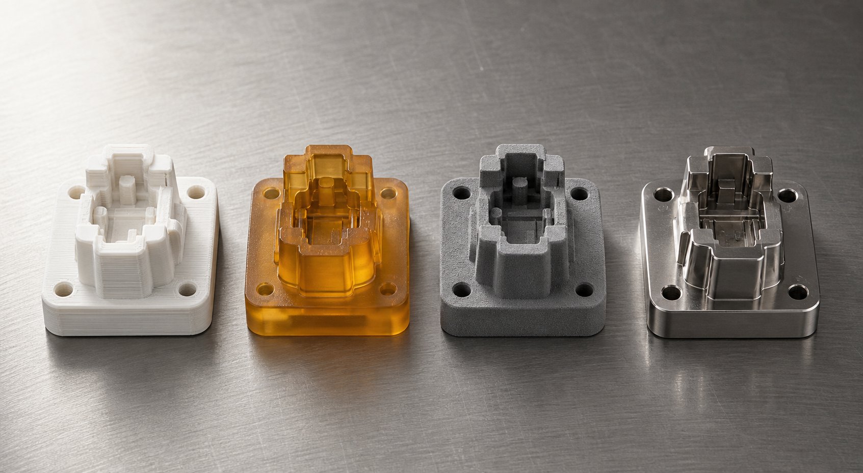
Comparing 3D Printing Technologies for Die Making
Die performance starts with the printing process itself. Each additive manufacturing technology deposits or fuses material differently, and those differences translate directly into compressive strength, surface quality on formed parts, and how many hits a die survives before degrading. Choosing the best 3D printing technology for stamping dies means matching process characteristics to your forming demands, not defaulting to whatever printer sits on your bench.
FDM Dies for Low-Force Forming
Fused deposition modeling is the most accessible entry point. You're extruding thermoplastic filament layer by layer, which means die cost stays low and turnaround is fast. Materials range from basic PLA and PETG up to nylon and carbon-fiber-reinforced composites that significantly boost compressive strength.
Infill density is the critical variable here. A die printed at 40% infill will crush under press loads that a 100% solid die handles comfortably. For stamping applications, you'll typically run 80-100% infill with gyroid or cubic patterns to distribute force evenly through the part. Carbon-fiber-filled nylon pushes compressive performance further, making FDM viable for forming thin aluminum and copper sheet under low tonnage on arbor or hydraulic presses.
The tradeoff is surface finish. FDM parts exhibit visible layer lines with Ra values typically ranging from 10 to 25 micrometers, and that texture transfers directly to formed parts. For functional prototypes where cosmetics don't matter, this is acceptable. For anything visible, post-processing the die face becomes mandatory. FDM vs SLA for metal forming dies often comes down to whether you can tolerate that surface roughness or need precision from the start.
Resin-Based Dies for Precision Forming
Stereolithography and DLP printers cure liquid photopolymer with light, producing dies with dramatically better dimensional accuracy and smoother surfaces than FDM. Engineering resins like rigid glass-filled, tough, and ceramic-filled formulations offer the stiffness needed for forming operations. SLA parts achieve tight tolerances with surface finishes that approach injection-molded quality, meaning the resin printed die surface finish quality carries over to cleaner formed parts without heavy post-processing.
The limitation? Brittleness under impact. Engineering resins handle static compressive loads well but can chip or crack if subjected to sudden shock loading. This makes resin dies better suited to controlled hydraulic presses than mechanical presses with fast ram speeds. They excel for shallow draws, embossing, and forming operations where precision matters more than raw tonnage. Dimensional accuracy of plus or minus 0.15% on features under 30mm means your punch-to-die clearances stay tight, reducing burrs and improving formed part edges.
SLS and Metal Sintered Dies for Production Loads
When forming forces exceed what polymers can handle, powder-based processes step in. Selective laser sintering fuses nylon powder (typically PA12 or PA11) into parts with excellent mechanical characteristics. SLS nylon stamping die strength approaches injection-molded nylon, with isotropic properties that eliminate the layer-direction weakness common in FDM. The self-supporting powder bed also allows complex die geometries, internal channels, and undercuts that would require supports in other processes.
SLS nylon handles moderate press loads and works well for forming thin mild steel and heavier gauge aluminum. Surface roughness sits around Ra 10-20 micrometers, similar to FDM, so die faces still benefit from finishing for cosmetic parts.
For dies approaching traditional tool steel performance, DMLS metal sintered die for press tooling is the answer. Direct metal laser sintering builds dies from stainless steel, maraging steel, or tool steel powders. These dies handle high tonnage, offer excellent wear resistance, and can incorporate features impossible with subtractive machining, like conformal cooling channels. The tradeoff is cost and lead time. DMLS parts have Ra values between 5 and 15 micrometers as-printed and typically require post-machining on critical surfaces. As noted by Xometry, compressive strength of metal 3D prints averages 40-50% lower than CNC-machined equivalents, but for many stamping applications this still exceeds requirements.
| Technology | Common Die Materials | Max Press Tonnage Range | Surface Finish (Ra) | Cost Per Die (Typical) | Lead Time |
|---|---|---|---|---|---|
| FDM | PLA, PETG, Nylon, Carbon-Fiber Nylon | 0.5 - 5 tons | 10 - 25 µm | $5 - $50 | 4 - 24 hours |
| SLA / DLP | Tough Resin, Rigid Glass-Filled, Ceramic-Filled | 1 - 8 tons | 1 - 5 µm | $30 - $150 | 3 - 12 hours |
| SLS | Nylon 12 (PA12), Nylon 11, Glass-Filled Nylon | 3 - 15 tons | 10 - 20 µm | $80 - $300 | 1 - 3 days |
| DMLS | Stainless Steel, Maraging Steel, Tool Steel | 15 - 100+ tons | 5 - 15 µm | $500 - $5,000+ | 3 - 10 days |
The tonnage ranges above assume proper die design with adequate wall thickness and infill. Actual limits depend on blank size, material being formed, and draw depth. A carbon-fiber nylon FDM die forming 0.5mm aluminum over a small area behaves very differently from the same material trying to handle a large blank with deep geometry.
Each technology occupies a distinct zone in the cost-performance spectrum. FDM gets you a working die for a few dollars and a few hours. SLA trades slightly higher cost for precision and finish. SLS delivers production-grade polymer strength without the anisotropy concerns. DMLS bridges the gap to traditional hardened tooling at a fraction of the lead time. The right choice depends less on which process is "best" and more on what your sheet metal, your press, and your part count actually demand, factors that live in the design details of the die itself.
Design Principles That Make 3D Printed Dies Perform
Selecting the right printing technology only gets you halfway to a functional die. The other half lives in how you design it. A poorly designed die printed on an expensive SLS machine will fail faster than a well-designed FDM die under the same press load. These design-for-additive principles are specific to stamping applications and directly determine whether your die survives ten hits or ten thousand.
Infill Strategy and Wall Thickness for Load Bearing
Standard 3D printing advice suggests 20-50% infill for general parts. Stamping dies are not general parts. You're dealing with concentrated compressive forces that will crush any low-density internal structure. For die applications, infill density should sit between 80% and 100%, with 100% solid being the safest default for small dies under moderate loads.
The infill pattern for 3D printed die strength matters just as much as density. As Raise3D's infill research explains, gyroid infill provides isotropic mechanical properties, meaning it resists forces equally from multiple directions. Cubic infill offers similar omnidirectional strength through its stacked 3D grid structure. Both outperform simpler patterns like grid or lines for stamping applications because press forces rarely arrive perfectly aligned with a single axis. Triangular infill also performs well under perpendicular loads due to its geometric stability, making it suitable for dies experiencing direct downward force.
Wall thickness amplifies this internal strength. According to Markforged's engineering data, shells (outer walls) have a greater impact on part flexural strength than infill alone, following sandwich panel theory. For stamping dies, this means thick perimeter walls of 3-5mm combined with high-density infill create a composite structure that resists both compression and lateral forces during forming.
Print orientation relative to the press direction is where many engineers make their first critical mistake. Deposition-based printers build parts in layers, and those interlayer bonds are the weakest point in any FDM or SLA part. Vertical forces will split parts along layer lines. The solution for print orientation for press load bearing is straightforward: orient the die so that layers stack perpendicular to the press force direction. This means the ram pushes down across the layer planes rather than trying to shear them apart. When layers run parallel to the press bed, compressive loads distribute along the filament strands rather than stressing the weaker adhesive bonds between layers.
CAD Workflow for Die Clearances and Springback
Sounds complex? The CAD design for a 3D printed stamping die follows the same engineering fundamentals as traditional die design, just with faster feedback loops. Start with punch-to-die clearance. The gap between punch and die cavity must account for material thickness plus a clearance allowance, typically 5-10% of the sheet thickness per side for clean shearing, or tighter for forming operations where you want controlled material flow.
Draft angles deserve attention for part release. Without draft on vertical die walls, the formed part will stick in the cavity, and pulling it free can damage both the workpiece and a polymer die face. A minimum of 2-3 degrees of draft on all vertical surfaces prevents this. Deeper draws need more draft, sometimes up to 5-7 degrees depending on material and surface friction.
Springback compensation in printed die geometry is where 3D printing delivers a distinct advantage over traditional tooling. As Spatial's engineering analysis explains, springback occurs because some atoms in bent sheet metal haven't rearranged past their yield point and continue exerting elastic stresses to restore the original shape. The amount of springback depends on material type, thickness, bend radius, and forming process. Designers compensate by overbending: shaping the die so the metal springs back to the desired final angle.
Here's the practical reality. Springback compensation formulas give you a starting point, but real-world results often require iteration. Material properties vary between batches, and complex geometries create compound springback effects that are difficult to predict analytically. With CNC-machined dies, each iteration means days of reprogramming and remachining. With a printed die, you adjust the CAD model and have a revised die in hours. This rapid iteration cycle transforms springback compensation from a frustrating guessing exercise into a systematic convergence process: print, form, measure deviation, adjust geometry, repeat until the part hits tolerance.
Designing for Printability Without Sacrificing Function
A die that performs perfectly in CAD still needs to come off the printer successfully. Overhangs beyond 45 degrees require support structures, and those supports leave witness marks on die surfaces that contact the workpiece. Plan your orientation so that critical forming surfaces face upward or sit at self-supporting angles. If supports are unavoidable on a forming face, budget time for post-processing those areas smooth.
Bridging, where the printer spans an unsupported gap, works reliably up to about 10-15mm on most FDM machines. Die cavities wider than this need internal support or a design that avoids flat horizontal ceilings in unsupported spans. For large dies that exceed your printer's build volume, splitting the die into sections is the practical answer. Use dowel pin holes, alignment keys, or interlocking geometry to ensure the sections register precisely when bolted together.
Keep these rules accessible during your CAD workflow:
- Set infill to 80-100% with gyroid, cubic, or triangular patterns for isotropic compressive strength
- Maintain minimum 3mm wall thickness on all perimeter surfaces, increasing to 5mm+ for high-load areas
- Orient the die so layer planes run perpendicular to the press force direction
- Apply punch-to-die clearance of material thickness plus 5-10% per side for blanking, tighter for forming
- Include 2-3 degrees minimum draft on all vertical die cavity walls
- Overbend die geometry to compensate for material springback, using printed iterations to converge on final shape
- Keep critical forming surfaces on the upward-facing side during printing to avoid support marks
- Limit unsupported horizontal spans to 10-15mm or redesign with self-supporting angles
- Split dies exceeding build volume into sections with dowel pin or key alignment features
- Add 0.5-1mm extra stock on forming surfaces designated for post-processing
These rules aren't constraints that limit your die, they're the framework that makes printed dies reliable under real press loads. A die designed with these principles built in from the start will outperform one where geometry was optimized for forming alone without considering how additive manufacturing actually builds the part. The next challenge comes after printing: how raw printed surfaces and inherent material limitations respond to repeated forming cycles, and what you can do to extend die life before ever pressing a blank.
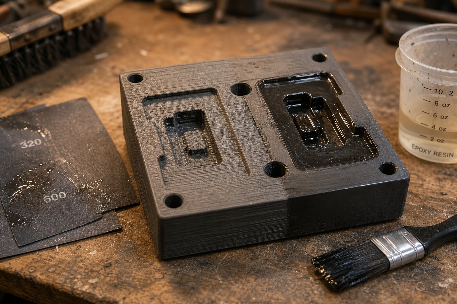
Post-Processing 3D Printed Dies for Durability and Finish
A die fresh off the print bed is not a finished tool. Every layer line, micro-void, and surface irregularity on that raw print will transfer directly to your formed sheet metal parts. Worse, those same imperfections act as stress concentrators that shorten die life under repeated press cycles. Post processing a printed die for sheet metal work isn't optional polish - it's what separates a die that survives fifty hits from one that lasts five hundred or more.
Surface Finishing Methods for Better Part Quality
When you press sheet metal against a 3D printed die face, the metal conforms to every imperfection. Layer lines that measure 10-25 micrometers on an FDM die will emboss faintly into soft aluminum. For functional prototypes where cosmetics are irrelevant, you might tolerate this. For any visible surface - or any application where surface roughness affects downstream processes like painting or welding - surface finishing for the printed metal forming die face becomes critical.
Sanding is the most universal approach and works across all polymer and metal printing technologies. Start with 120-200 grit to knock down prominent layer lines and ridges, then progress through 400, 800, and up to 2000+ grit for a near-polished surface. Wet sanding with water and a drop of dish soap keeps the plastic cool, prevents friction-induced melting on thermoplastics, and flushes debris so your paper doesn't clog. The key is working only the die face - the surfaces that contact the workpiece - rather than finishing the entire part.
For ABS or ASA printed dies, vapor smoothing offers a chemical shortcut. Acetone vapor smoothing exposes the print to evaporated solvent inside a sealed chamber, chemically melting the outermost layer so it flows together and cures into a glossy shell. The process erases layer lines entirely and produces a surface approaching injection-molded quality. Timing is critical: 30 minutes to two hours depending on part size and vapor concentration, monitored through a transparent glass container. Over-exposure melts fine features and destroys dimensional accuracy on forming radii. This technique is strictly limited to ABS and ASA - PLA, PETG, and nylon are resistant to acetone and require mechanical finishing instead.
Coating is the third path. Spray-on polyurethane, brushed epoxy, or automotive filler primer applied to sanded die faces fills micro-pores and creates a harder contact surface. A thin coat of two-part epoxy on the forming face smooths remaining irregularities while adding a wear-resistant shell that outlasts bare polymer. For dies forming aluminum or copper, a coat of dry-film lubricant (PTFE or moly-based) over the finished surface reduces friction and galling during forming.
Reinforcement Techniques to Extend Die Life
Surface finish handles part quality. Reinforcement handles die longevity. Raw 3D prints suffer from interlayer bond weaknesses, internal micro-voids from incomplete fusion, and compressive strength limits inherent to their base polymer. Each of these failure modes can be mitigated through targeted post-processing.
Epoxy infiltration is one of the most effective and accessible methods to reinforce a 3D printed stamping die. The process involves saturating the printed part with liquid epoxy resin, which penetrates micro-voids and fills gaps between layers. Research published in Polymers (2025) demonstrated that viscosity-controlled epoxy infiltration of 3D-printed polypropylene structures significantly enhanced mechanical performance. Medium-viscosity epoxy (300-560 cP) achieved the best balance between internal void filling and surface film formation, yielding approximately 80% higher specific energy absorption compared to untreated specimens. The study confirmed that this improvement was attributed to epoxy filling internal voids and reinforcing weak interlayer bonds, creating weld-like connections at layer interfaces.
For stamping dies specifically, epoxy infiltration 3D printed die strength gains mean higher compressive load capacity before failure and more gradual degradation rather than sudden catastrophic cracking. Ultrasonic bath-assisted infiltration improves penetration depth, though even simple brush-on or dip application provides measurable improvement for low-volume forming.
Beyond epoxy, reinforcement scales up with your production needs. Fiberglass cloth laminated onto the back face of a printed die adds crack resistance and prevents sudden brittle failure - the die may deform under overload but won't shatter into fragments. Metal backing plates bolted to the rear of printed die faces provide rigid support that distributes press force evenly across the entire printed structure, preventing localized crushing. For the highest performance short of fully metal-printed dies, conformal metal shells - thin steel or aluminum plates machined to match the die face contour - mount over printed cores, combining the geometric complexity of additive manufacturing with the wear resistance of metal surfaces.
How do you choose? Match the approach to your expected part count and forming severity:
- Sanding and surface sealing - Simplest and cheapest. Suitable for 1-20 parts where die wear is minimal and cosmetic improvement on formed parts is the primary goal. Requires only sandpaper and spray sealer. Budget 30-60 minutes of labor.
- Epoxy infiltration - Moderate effort, significant strength gain. Dip or brush the entire die in low-to-medium viscosity epoxy (300-560 cP range yields the best internal penetration). Adds 20-40% to die mass and substantially improves compressive capacity. Suitable for 20-100+ parts depending on forming severity. Requires 24-hour cure time.
- Fiberglass backing lamination - Adds fracture toughness for dies under repeated cyclic loading. Apply fiberglass cloth and resin to the non-forming faces. Prevents crack propagation and catastrophic failure. Suitable for 50-200 parts at moderate forming loads. Adds a day of preparation and cure.
- Metal backing plate - Bolting a machined steel or aluminum plate to the die base distributes press force and prevents localized crushing. The printed face handles forming geometry while the plate handles structural load. Suitable for 100-500+ parts, especially when die geometry is complex but loads are concentrated. Requires basic machining of the backer plate.
- Conformal metal shell over printed core - Maximum durability. A thin machined metal face mounts over a 3D printed core that provides complex internal geometry or conformal features. The metal surface contacts the workpiece and resists wear while the printed structure provides form. Suitable for 500+ parts or aggressive forming where polymer contact surfaces would degrade rapidly. Highest cost and lead time of the post-processing options, but still faster than machining a full die from billet.
Each level builds on the previous ones. You might sand and seal a die, then add epoxy infiltration when you realize you need more hits. Or you might start with a metal-backed design because you already know you're forming 200 parts in 1mm mild steel. The point is that post-processing is not a single binary step - it's a spectrum you move along based on what the job actually demands.
These reinforcement strategies address internal weakness and surface wear, but they don't change the fundamental physics of how much force your die material can sustain. Understanding where those force limits sit - and what happens when you exceed them - determines whether your post-processed die survives its planned run or fails mid-production.
Cost and Lead Time Framework for Die Selection
Force limits and die longevity define what's physically possible, but cost and lead time determine what's economically rational. Engineers often default to familiar CNC-machined tooling without running the numbers on additive alternatives - or they assume printed dies are always cheaper without accounting for lifespan and cycle time differences. The reality requires a structured 3d printed die cost vs CNC machined tooling comparison that accounts for every dollar and day in the process.
Direct Cost Breakdown by Die Complexity
Every die fabrication method carries four core cost components, and they distribute very differently between additive and subtractive approaches:
- Material cost - A polymer FDM die might consume $5-50 in filament. An SLS nylon die runs $80-300 in powder. A CNC-machined die starts with a billet of tool steel that alone costs $100-500+ depending on die size, before any cutting begins.
- Machine time - Printing a die takes hours (FDM/SLA) to a few days (SLS/DMLS). CNC machining a comparable die involves programming, multiple setups with re-fixturing between operations, and actual cutting time that scales sharply with geometric complexity.
- Labor - For printed dies, labor covers CAD design and post-processing (sanding, infiltration, assembly). For CNC dies, labor includes CAM programming, machine setup, tool changes, fixture fabrication, and potential EDM or grinding operations for complex forming surfaces.
- Amortization - Traditional tooling spreads cost across thousands of parts. Printed dies typically serve tens to hundreds of parts, meaning amortization calculations differ fundamentally.
The structural cost comparison of additive manufactured dies reveals an important pattern. Manufacturing cost analysis shows that 3D printing carries minimal tooling and non-recurring engineering cost compared to other methods, while CNC machining maintains a relatively linear cost structure where per-unit cost stays fairly constant. The hidden multiplier in traditional die making is setup complexity: each additional feature, pocket, or contour on a stamped part adds CNC setups, tool paths, and fixturing operations. A printed die absorbs geometric complexity at near-zero marginal cost - a die with ten forming features costs barely more to print than one with two.
Consider the total cost formula: Tooling (NRE) + (Unit Cost x Quantity) + Secondary Operations. For a simple forming die, traditional CNC might cost $2,000-5,000 in tooling NRE with near-zero per-part cost across thousands of hits. An FDM die costs $20-50 in NRE but may need reprinting every 50-200 parts. The math tilts heavily depending on your production volume.
Lead Time Comparison Across Methods
Lead time for a 3D printed stamping die is measured in hours. Lead time for conventional tooling is measured in weeks - sometimes months when you factor in shop queue time, material procurement, and secondary operations like heat treatment. This gap is where additive delivers its most dramatic advantage.
The difference extends beyond raw fabrication time. Industry data confirms that tooling fabrication for traditional methods can take 4 to 12 weeks, while 3D printing offers the fastest start of all manufacturing methods. Queue and capacity constraints mean your CNC die job is rarely the only one in the shop. Material procurement for specialized tool steels may add days. Documentation and heat treatment add more. Each of these steps disappears entirely from the printed die workflow.
The iteration cycle - how quickly you can modify a die and have a revised version ready - is where the cost-time advantage compounds. Fixing springback issues or adjusting forming radii on a CNC die means reprogramming, re-fixturing, and re-cutting. On a printer, it means editing the CAD file and pressing start.
| Method | Design-to-Ready Time | Iteration Cycle Time | Cost Per Iteration |
|---|---|---|---|
| Traditional CNC (tool steel) | 3 - 8 weeks | 1 - 3 weeks | $2,000 - $10,000+ |
| Cast Tooling (kirksite/aluminum) | 4 - 12 weeks | 2 - 4 weeks | $3,000 - $15,000+ |
| FDM Printed (polymer) | 4 - 24 hours | 4 - 12 hours | $5 - $50 |
| SLA Printed (resin) | 3 - 12 hours | 3 - 8 hours | $30 - $150 |
| SLS Printed (nylon) | 1 - 3 days | 1 - 2 days | $80 - $300 |
Look at the iteration column. When a design change costs $30 and half a day versus $5,000 and two weeks, engineers iterate more frequently. That rapid feedback loop directly improves the final die design because you can test three or four geometry variations in the time one traditional revision would take. Research across manufacturing operations shows that lead time reductions approaching 90% are achievable when additive replaces traditional tooling fabrication for prototyping and low-volume applications.
Break-Even Volume Calculation Approach
The break even volume between printed die and traditional tooling depends on a straightforward calculation, though the inputs require honest estimates about die lifespan and production requirements.
Here's the framework. Calculate total cost for each approach across your expected production volume:
- Printed die path: (Cost per die x Number of dies needed) + (Cycle time penalty per part x Total parts) + Post-processing labor
- Traditional die path: Tooling NRE + (Minimal per-part cost x Total parts) + Heat treatment + Maintenance
The number of dies needed equals your total part count divided by die lifespan. If an epoxy-infiltrated FDM die lasts 150 parts and you need 600 parts, that's four dies at $40 each plus labor - $160 in die cost plus perhaps $200 in reprinting labor. Compare that to a $4,000 CNC die that handles all 600 parts without replacement.
Three factors complicate this simple math:
- Cycle time differential - Polymer dies often require slower press speeds to avoid impact cracking. If each part takes 30 seconds on a traditional die versus 60 seconds on a printed die, multiply that delta by your volume to calculate the production time cost.
- Quality consistency - Traditional dies maintain dimensional accuracy across their entire lifespan. Printed dies may degrade gradually, meaning parts 1 and 100 from the same die could show measurable differences. If your tolerance requirements are tight, factor in the inspection and rejection costs.
- Iteration value - If your design is still evolving, the ability to modify a printed die cheaply has value that doesn't appear in per-part cost calculations. Committing $5,000 to a CNC die on a design that changes two months later is a sunk cost that printed dies avoid entirely.
For most applications, the crossover point lands somewhere between 200 and 2,000 parts depending on die complexity, forming severity, and quality requirements. Simple forming operations in soft metals with modest tolerance demands push the break-even higher - printed dies remain competitive longer. Complex dies forming harder materials with tight tolerances push the crossover lower, making traditional tooling economical sooner. Cost-volume analysis across manufacturing methods consistently shows that 3D printing maintains a relatively flat cost curve, while traditional tooling methods exhibit high initial spikes that drop sharply as volume amortizes the NRE investment.
The practical takeaway: run this calculation with your actual numbers before committing either direction. Many engineers default to traditional tooling out of habit when their volumes sit squarely in the zone where printed dies deliver better economics. Others assume printed dies are always cheaper without accounting for replacement frequency and labor. Neither assumption serves you - the math does.
Economics and lead time determine which fabrication path makes sense, but they don't tell you whether your die will survive the specific forces and cycle counts your application demands. Understanding press tonnage limits and realistic die lifespan expectations is what turns a cost-justified decision into a functionally successful one.
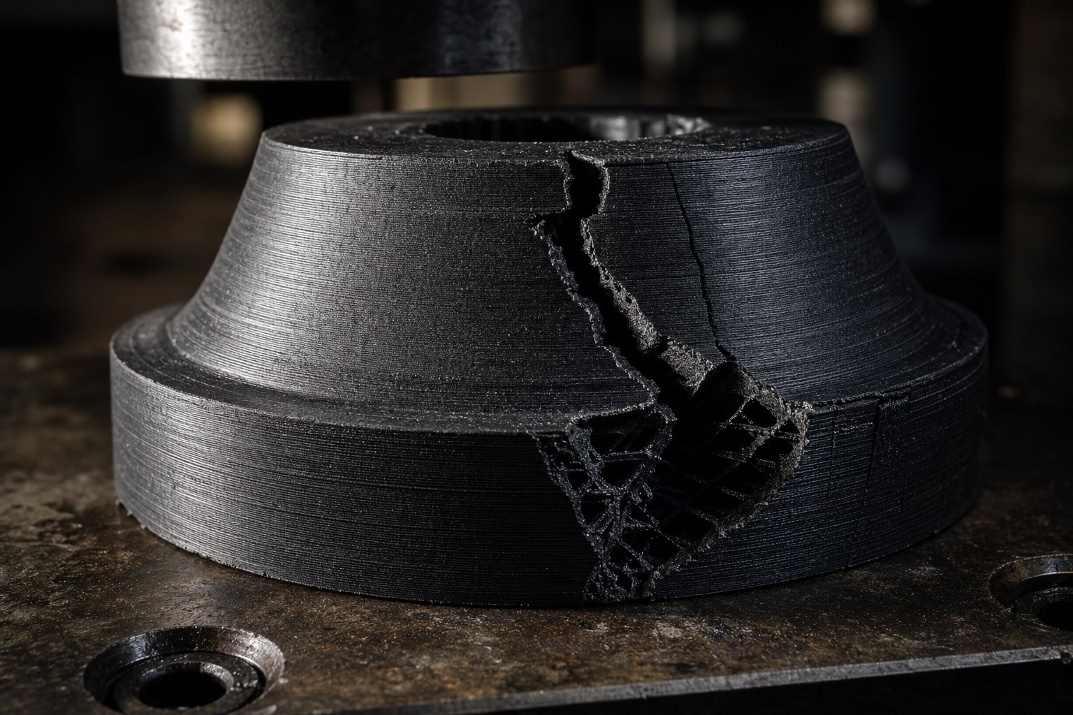
Press Tonnage Limits and Die Lifespan Expectations
Cost analysis tells you whether a printed die makes financial sense. But the die doesn't care about your spreadsheet - it cares about the force pushing through it every cycle. Understanding the press tonnage limit for a 3D printed die, and what happens when you exceed it, is the difference between a controlled tool life and a mid-run failure that scraps parts and delays production.
Understanding Force Limits for Printed Die Materials
The compressive strength of your die material sets the absolute ceiling on forming force. Exceed it, and the die crushes, cracks, or deforms permanently. Stay within it, and the die performs predictably across its rated service life. The compressive strength requirements for printed dies depend on a straightforward calculation: how much tonnage does your forming operation actually demand?
Here's how to estimate required press tonnage for a basic bend or form. You need three inputs: the material being formed (its tensile strength), the blank dimensions (length and thickness of the bend line), and the forming geometry (V-opening width for bending, draw depth and reduction ratio for deeper forms). For air bending, a common simplified formula is:
Required tonnage per foot = (575 x Material Thickness² x Tensile Strength) / (V-Die Opening x 12)
Where thickness is in inches, tensile strength is in tons per square inch, and V-die opening is in inches. The result gives tonnage per linear foot of bend. Multiply by your bend length in feet for total force on the die.
Relate this back to technology selection. Real-world testing with fiber-reinforced nylon dies has shown that roughly 8-10 tons per foot in air bending represents the practical upper boundary for well-designed polymer tooling. High-infill carbon-fiber nylon at 100% density, with layers oriented to keep the compressive load traveling along filament paths, has survived 12 tons per foot - but at that level you're operating at the material's edge, where a slight misalignment or blank irregularity can trigger sudden failure.
The general principle works like this: FDM and SLA polymer dies handle thin aluminum and copper comfortably at 1-5 tons total force. SLS nylon extends the envelope to moderate loads on thin mild steel. DMLS metal-sintered dies approach traditional steel die performance and can handle tonnages that would instantly destroy any polymer. When your tonnage calculation lands above 10 tons per foot for polymer or above 15 tons per foot for SLS nylon, you've crossed into territory where metal tooling - either DMLS or conventional - becomes the only safe option.
Die Lifespan and Failure Modes to Expect
How long do 3D printed stamping dies last? The honest answer: it depends heavily on material, forming severity, and post-processing. But general ranges give you planning baselines. Unreinforced FDM dies forming thin aluminum at low tonnage typically survive 20-100 parts before visible degradation. Epoxy-infiltrated FDM or SLS nylon dies operating well within their tonnage window can reach 200-500 parts. Documented field use of fiber-reinforced nylon dies at controlled loads shows 100-200 clean hits as a realistic, repeatable service life for air bending within the rated tonnage window. Metal-sintered DMLS dies, depending on material and forming conditions, can approach thousands of cycles.
These numbers assume you're operating inside the design envelope. Push beyond it - narrower V-openings than calculated, harder material than specified, impact loading from a mechanical press at full speed - and lifespan collapses dramatically.
The failure modes of printed forming dies follow predictable patterns, and recognizing them early prevents catastrophic mid-run failures:
Layer delamination under cyclic loading is the most common and most dangerous failure mode for FDM and SLA dies. Each press cycle introduces tensile stress at the die shoulders that tries to peel layers apart along their bond planes. Research on 3D-printed composite delamination confirms that interlayer adhesion is the primary weak point under repeated cyclic bending loads, with filler ratio and layer height being the most significant parameters affecting fracture strength. In a die context, delamination starts as a hairline crack at the V-root or shoulder radius, then propagates outward with each hit until the die separates violently.
Surface wear and galling appears gradually. The die face polishes first, then rounds at forming radii. On polymer dies forming aluminum, initial surface wear actually reduces marking on parts - but continued wear widens the effective forming geometry. Your V-opening grows by thousandths per hundred cycles, changing bend radius and springback behavior. Parts that measured 90.0 degrees at cycle 10 might read 89.2 degrees at cycle 300, not because the press changed but because the die crept.
Edge chipping on sharp forming radii affects brittle materials most - particularly SLA resins and unfilled PLA. Sharp internal corners concentrate stress, and polymer corners lack the ductility to yield gracefully. They chip. Each chip creates a stress riser that accelerates the next chip.
Catastrophic cracking from exceeding compressive limits happens suddenly and loudly. Unlike steel, which yields plastically before failing, polymer stores elastic energy and releases it all at once. A die operating at 95% of its compressive capacity might survive dozens of cycles, then fail explosively on a hit where the blank catches slightly off-center or the press bottoms harder than intended.
Watch for these warning signs that indicate when to retire a printed die:
- Visible hairline cracks at the V-root, die shoulder, or any radius - even if the die still forms parts, crack propagation is underway
- Audible change in the forming sound - a shift from dull compression to sharper cracking tones indicates internal delamination beginning
- Measurable angle drift on formed parts exceeding half your tolerance band - the die geometry is creeping
- Surface rounding visible to the eye at forming radii - wear has progressed beyond superficial polishing
- Any asymmetric deformation or visible bulging on die sidewalls - lateral spreading means internal structure is failing
- Formed parts showing inconsistent marks, scratches, or surface defects that weren't present on earlier cycles
- Die rocking or shifting in its holder when it previously sat flat - dimensional distortion of the base
The critical mindset shift: retire the die at the first sign of degradation, not after it fails. A printed die costs hours and dollars to replace. A failed die mid-run costs scrapped parts, potential press damage, and schedule disruption worth far more.
Strategies to Maximize Die Longevity
Maximizing 3D printed die lifespan doesn't mean making the die indestructible. It means extending useful service life within the die's rated operating window through intelligent use practices.
Load distribution techniques spread force more evenly across the die structure. Use wider V-openings where your bend radius tolerance allows - this drops tonnage per foot and distributes contact pressure across broader shoulder areas. Ensure the die seats flat and uniform in its holder with no rocking; feeler gauges along the die length confirm contact. Any gap introduces point loading that the die was never designed to absorb. For large dies assembled from sections, verify that section joints don't align with high-stress zones.
Progressive forming in multiple lighter hits reduces peak stress per cycle at the cost of longer cycle time. Instead of forming a 90-degree bend in one full-depth stroke, consider partial bending in two or three passes at reduced ram depth. Each pass applies less force to the die shoulders. This works particularly well for deeper forms or harder materials that push toward the upper tonnage boundary. The die sees half the peak stress per hit, and stress-related degradation scales with peak load, not cumulative load.
Die rotation schedules apply when you're running enough volume to justify printing multiples. Print two or three identical dies and rotate them every 50-100 cycles. This allows each die to rest between runs - important because polymer under sustained cyclic loading experiences localized heating at stress points that softens the material incrementally. Letting the die cool and recover between shifts extends total service life beyond what continuous running would deliver. It also gives you inspection windows to catch early warning signs before they become failures.
Combine these strategies with appropriate post-processing from the previous section, and you've built a system around managing die life rather than hoping for it. The question then shifts from whether your die can handle the job to which application tier - hobbyist, prototyping, or low-volume production - represents the best fit for your specific combination of material, volume, and quality requirements.
Best Use Cases for 3D Printed Stamping Dies by Application Tier
Tonnage limits and lifespan data give you the physical boundaries. But knowing a die can survive 200 hits doesn't tell you whether it belongs in your garage workshop or on a production floor. The best use cases for 3D printed stamping dies depend not just on material science but on who's using them, what they're forming, and what "good enough" actually means for the finished part. Three distinct application tiers emerge, each with different technology choices, investment levels, and success criteria.
Hobbyist and Maker Applications
Imagine you're building custom motorcycle emblems, forming decorative copper panels for a furniture project, or pressing small aluminum brackets for a robot chassis. You don't need production-grade tooling. You need a die that works this afternoon for ten parts.
A 3D printed die for hobby metal forming starts with what you already have: a desktop FDM printer and a manual or arbor press. The workflow is simple. Model the die geometry in free CAD software, slice at 100% infill with a gyroid pattern, print in PLA+ or PETG, and press thin soft metals - typically aluminum under 1mm or copper sheet under 0.8mm. Documented maker experiments show that solid PLA+ dies successfully stamp logos and forming features into 1-2mm sheet metal using a standard hydraulic press, with dies surviving roughly a dozen hits before showing wear but not failing outright.
Cosmetic quality on formed parts is secondary at this tier. Layer lines may transfer to the workpiece, forming radii won't be perfectly sharp, and dimensional precision sits within roughly 0.3-0.5mm. None of that matters when you're making one-off brackets, decorative pieces, or functional prototypes where fit matters more than finish.
The investment? A capable FDM printer runs $200-500. An arbor press costs $50-150. Filament per die costs $2-10. You're producing custom metal forming tooling for less than the price of a single outsourced machined bracket. The tradeoff is limited forming force, rough surfaces, and short die life - all perfectly acceptable when your production run is five parts and your deadline is tomorrow.
Professional Prototyping and Engineering Validation
This tier is where 3D printed dies deliver their highest return on investment. You're an engineer designing a stamped sheet metal component that will eventually run on a $50,000 progressive die. Before committing that capital, you need to confirm the part geometry works: does it fit the assembly? Does springback land within tolerance? Do the forming features interact with each other in ways the simulation didn't predict?
Prototyping stamped parts with printed dies answers these questions in days, not months. Engineering-grade resins (rigid glass-filled or tough formulations) or SLS nylon give you the accuracy needed for meaningful dimensional validation. Hydraulic presses at 5-15 tons provide enough force for realistic forming of thin to moderate gauge aluminum and mild steel. Engineering case studies demonstrate that SLA-printed dies in rigid resin withstand forming loads on 18-22 gauge steel, with engineers iterating through six design revisions in a single day before settling on a final geometry - a process that would take weeks per iteration with traditional machined tooling.
The ROI calculation at this tier is indirect but enormous. Every design error caught with a $30-150 printed die is an error that doesn't require recutting a $5,000 production die. A single avoided production die revision pays for an entire year's worth of resin and printer depreciation. This is the application tier where the Formlabs cost data becomes most compelling: in-house printed tooling at $40 per die set versus $460 for outsourced metal tooling, with lead times dropping from 25 business days to under 24 hours.
Surface finish matters more here because you're evaluating formed part quality, not just fit. SLA dies produce smoother forming surfaces without post-processing. For FDM or SLS dies at this tier, expect to sand forming faces to at least 400-grit before pressing validation parts, ensuring that surface artifacts from the die don't mask real forming defects in the stamped component.
Low-Volume Production Runs
Sometimes traditional tooling cost simply cannot be justified. You need 50 stamped brackets for a limited-edition product. Or 200 formed housings for a specialty piece of equipment. Or 30 custom enclosures for an industrial control panel. The per-part cost of $5,000 traditional tooling spread across 50 units makes each bracket carry $100 in tooling burden alone. Low volume production 3d printed tooling changes that equation entirely.
At this tier, reinforced printed dies or metal-sintered dies serve as actual production tools. Epoxy-infiltrated carbon-fiber nylon dies, backed with steel plates, can produce hundreds of consistent parts in aluminum or thin mild steel. DMLS tool steel dies handle harder materials and tighter tolerances for runs where polymer would degrade too quickly. The key distinction from prototyping is repeatability: you need part 200 to match part 1 within spec.
Die wear management becomes a real production consideration here. You might plan for two or three die replacements across a 300-part run, printing spares in advance and rotating them to maintain consistent part quality. The total tooling cost - three printed dies at $80-300 each, plus post-processing labor - still runs well under a single conventional die that would handle the same volume without replacement.
Quality requirements define where this tier stops working. If parts feed into safety-critical assemblies, require certified tooling traceability, or demand surface finish that only hardened ground steel can deliver, you've exceeded what printed production dies can guarantee. But for commercial sheet metal parts with standard tolerances - the vast majority of low-volume work - printed dies produce economically viable results that traditional tooling economics would make impossible to justify.
| Use Case Tier | Recommended Technology | Typical Materials Formed | Expected Die Life Range | Investment Level |
|---|---|---|---|---|
| Hobbyist / Maker | FDM (PLA+, PETG, Nylon) | Aluminum under 1mm, copper, brass sheet | 10 - 50 parts | $200 - $700 (printer + press) |
| Professional Prototyping | SLA / DLP (Rigid, Tough Resin) or SLS (PA12) | Aluminum 0.5-2mm, mild steel 18-22 gauge | 50 - 200 parts per die | $3,000 - $15,000 (printer + hydraulic press) |
| Low-Volume Production | Reinforced SLS, Carbon-Fiber FDM with backing, or DMLS metal | Aluminum, mild steel, stainless up to 1.5mm | 100 - 1,000+ parts (with die rotation) | $5,000 - $50,000+ (industrial press + printer or print service) |
Notice how each tier maps cleanly to the technology comparison and cost framework from earlier sections. A hobbyist doesn't need SLS nylon - FDM handles their loads at a fraction of the cost. A production shop doesn't benefit from $5 FDM dies that wear out every 30 parts when a $300 SLS die with epoxy infiltration lasts 500. The decision path isn't about which technology is "best" in absolute terms. It's about which technology delivers the performance your tier demands at a cost your tier can absorb.
The tier matrix also reveals a pattern: as you move up, the gap between printed die capability and traditional tooling performance narrows. At the hobbyist level, printed dies do things no affordable traditional tooling could. At the production level, printed dies are a pragmatic compromise - they work, but with acknowledged limitations in lifespan, tolerance control, and material compatibility. Recognizing exactly where those limitations become disqualifying is what separates a smart tooling decision from an expensive lesson.
When NOT to Use 3D Printed Stamping Dies
Every technology has boundaries, and pretending otherwise wastes time and money. The previous tier matrix shows where printed dies excel - but it also hints at a ceiling. Cross that ceiling, and you're not pushing the envelope. You're setting yourself up for failed runs, scrapped parts, and a return to traditional tooling anyway, minus the weeks you spent trying to make printed dies work in an application they were never suited for.
Knowing the limitations of 3D printed stamping dies before you commit a project to them is worth more than any number of successful test prints. Here's where they fall short - honestly.
Material and Geometry Limitations
Printed dies perform well within a defined envelope: thin soft metals, moderate forming depths, and reasonable tonnage. Step outside that envelope and failure isn't gradual - it's immediate.
Thick high-strength steel is the clearest disqualifier. Forming 2mm DP980 or 3mm HSLA steel demands tonnages that obliterate any polymer die instantly. Even metal-sintered DMLS dies face challenges here. Research at Oakland University demonstrated that coated 3D-printed inserts could stamp 1mm DP980 ultrahigh-strength steel for 50,000 cycles - but those were metal-sintered inserts with specialized coatings on a carefully controlled die geometry. Polymer dies would not survive a single cycle at those forming loads. If your application involves advanced high-strength steels above 1mm thickness, traditional hardened tool steel is the only practical path.
Deep draws with high reduction ratios compound multiple failure mechanisms simultaneously. A deep draw subjects the die to sustained high contact pressure along the cavity walls, friction-induced heat buildup, and lateral forces that exploit interlayer weakness in printed parts. Reduction ratios above 40-50% generate forming forces and material flow conditions that demand the ductility and thermal stability of hardened steel. Polymer dies crack; resin dies shatter; even SLS nylon deforms under the sustained pressure of a deep cup draw in anything stronger than thin aluminum.
Tight-tolerance progressive dies with multiple stations present a different problem: cumulative precision. A progressive die strips a blank through five, ten, or twenty stations, each adding features with positional tolerances that stack. When every station must hold plus or minus 0.05mm relative to the others across thousands of cycles, printed materials simply cannot maintain that dimensional stability. Thermal expansion during operation, creep under sustained load, and gradual wear all introduce drift that compounds station to station. Traditional tool steel maintains its geometry to within microns across millions of cycles. No printed material matches that stability.
High-speed production where cycle time drives economics is another mismatch. Mechanical presses running at 30-60 strokes per minute subject dies to impact loading - rapid force application that polymer materials absorb poorly. The dynamic forces at speed significantly exceed the static forces of a slow hydraulic press. A die rated for 5 tons under controlled hydraulic forming may fail at 3 tons from a fast-cycling mechanical press because the strain rate sensitivity of polymers means they behave more brittly under rapid loading. Production environments where parts-per-hour directly affects unit cost need dies that tolerate aggressive cycling without the slower press speeds printed dies require.
Surface finish requirements for Class A panels set an absolute quality ceiling. Automotive exterior panels, consumer electronics housings, and any visible surface requiring a mirror-like finish after painting demand die surface quality measured in fractions of a micrometer. Even post-processed SLA dies with careful sanding cannot achieve the sub-0.4 micrometer Ra that ground and polished tool steel delivers. The 3D printed die is not suitable for high volume cosmetic production - not because of lifespan concerns, but because the surface quality simply isn't achievable regardless of post-processing effort.
The Break-Even Point with Traditional Tooling
Economics eventually favor conventional dies even when printed alternatives technically work. The printed die vs hardened steel tooling decision isn't always about capability - sometimes it's pure math.
The calculation is straightforward: when your production volume exceeds the printed die's lifespan multiplied by the number of reprinting cycles you're willing to manage, traditional tooling becomes the rational investment. If an SLS die lasts 300 parts and you need 5,000, that's 17 die replacements. At $250 per die plus an hour of post-processing labor each time, you've spent $4,250 in die cost and 17 hours of disruption - approaching the price of a single CNC die that handles the entire run without interruption.
But volume isn't the only trigger. Several non-volume factors push you toward conventional tooling:
Repeatability over thousands of cycles. Traditional dies don't drift. Part 1 and part 10,000 come off dimensionally identical because hardened D2 or A2 tool steel doesn't creep, wear negligibly with proper lubrication, and maintains its geometry under thermal cycling. If your application requires statistical process control with Cpk values above 1.33 across the full production run, printed dies introduce variation sources that undermine process capability.
Die accuracy for tight-tolerance assemblies. When your stamped part mates with other components in a precision assembly - medical devices, aerospace brackets, electronic enclosures with EMI shielding requirements - the tolerance band is consumed by the part itself. There's no room for die-induced variation. Traditional wire-EDM cut dies hold tolerances to 0.01mm or better. Printed dies start at 0.1-0.15mm accuracy under ideal conditions and drift from there.
Regulatory compliance and tooling certification. Aerospace (AS9100), automotive (IATF 16949), and medical device (ISO 13485) quality systems often require documented tooling materials, certified heat treatment, and traceable material properties. A 3D-printed die from a spool of filament lacks the material certification chain that auditors expect. Even if the printed die produces identical parts, the quality system may not accept it as validated production tooling. This isn't a technical limitation - it's a documentation and compliance reality that many engineers discover too late in a project.
Signs You Should Invest in Conventional Dies
When you find yourself hitting these walls, the decision to use traditional tooling instead of printed alternatives isn't a failure of the printed approach. It's a recognition that you've exceeded its design intent. Here are the clear decision triggers:
- Production volume exceeds 1,000-2,000 parts - At this point, die replacement frequency, cumulative labor, and production disruptions from swapping printed dies erode the cost advantage. A traditional die amortizes its higher upfront cost across the volume and runs uninterrupted.
- Forming forces exceed 10 tons per foot for polymer or 15 tons total for SLS nylon - You've crossed the structural threshold where printed materials cannot reliably survive. Continuing to try means unpredictable die failures, scrapped parts, and potential press damage from catastrophic die fracture.
- Surface finish requirements demand Ra below 1.0 micrometer on formed parts - No amount of post-processing brings a printed die face to the quality that ground tool steel provides. If your parts require painting, plating, or serve as visible consumer surfaces, traditional dies deliver what printed dies cannot.
- Tolerance stack-up across multiple forming features must stay within 0.1mm - Progressive forming, multi-station dies, or any operation where positional accuracy compounds across features needs the dimensional stability that only hardened steel maintains over thousands of cycles.
- Customer specifications or purchase orders mandate certified tooling materials - If your customer's print says "D2 tool steel, heat treated to 58-62 HRC" or your quality system requires material traceability on production tooling, printed dies are contractually non-compliant regardless of whether they produce acceptable parts.
- Cycle time requirements demand mechanical press speeds above 15-20 strokes per minute - Impact loading at production speed exceeds what polymer dies tolerate. The strain-rate sensitivity of plastics means they fail at lower forces under rapid loading than under slow hydraulic application.
- Material being formed is thicker than 2mm in mild steel or any gauge in advanced high-strength steel - The tonnage and friction forces involved exceed printed die capacity, and the abrasive nature of AHSS surface coatings accelerates die wear beyond practical replacement intervals.
- Die must maintain dimensional accuracy over 6+ months of intermittent production - Polymer creep, environmental humidity absorption (especially in nylon), and UV degradation over time affect stored printed dies. Steel tooling sits on a shelf indefinitely without dimensional change.
None of these triggers mean 3D printed dies failed you. They mean you've graduated past the application envelope where printed dies make sense. Many successful tooling strategies use printed dies for development and validation, then transition to conventional tooling for production - capturing the speed and cost advantages of additive where they matter most while respecting the performance boundaries where traditional methods remain superior.
The honest assessment is this: printed dies solve a specific set of problems brilliantly, and attempting to force them beyond those problems creates new ones. The smartest engineers know both when to print and when to machine. That boundary often sits in the middle ground - hybrid approaches that combine printed and conventional elements, or validation workflows that use printed dies to de-risk the transition to hardened production tooling.
Hybrid Approaches and Rapid Prototyping Validation
That middle ground between fully printed dies and fully machined tooling isn't just a compromise - it's often the smartest engineering choice available. Hybrid die strategies combine the geometric freedom and speed of additive manufacturing with the strength and surface quality of traditional materials. And when paired with a structured validation workflow, they eliminate the biggest risk in stamping die development: committing capital to production tooling based on unverified geometry.
Hybrid Die Strategies for Better Performance
A purely printed die has clear limitations. A purely machined die has clear cost and lead time penalties. Combining printed dies with metal backing plates, or using printed geometry as a foundation for more durable materials, gives you performance that neither approach delivers alone.
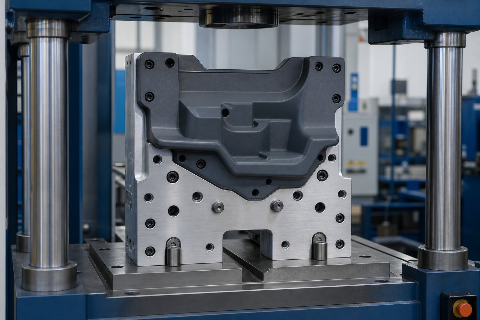
Printed die faces with machined metal backing plates. This is the most accessible hybrid 3d printed and machined die approach and requires no exotic equipment. Print the complex forming geometry - the contoured die face with its radii, draft angles, and springback compensation - in SLS nylon or reinforced FDM. Then bolt it to a machined steel or aluminum backer plate that handles the structural load from the press. The printed face provides geometric complexity at low cost. The metal plate provides rigidity, flatness, and force distribution that the printed material alone cannot match. You'll notice this approach works particularly well for larger dies where the printed section would otherwise deflect under press loads - the metal backing constrains deflection while the printed face handles the precision forming geometry.
Printed dies as patterns for urethane or aluminum casting. Here's where additive manufacturing extends beyond direct tooling into indirect rapid tooling. Print a master die geometry at high resolution on an SLA printer, then use it as a pattern to cast production dies in more durable materials. Vacuum casting workflows demonstrate that SLA-printed master patterns produce highly accurate mold cavities because silicone captures every detail of the printed surface. For stamping applications, a 3D printed die as casting pattern allows you to create urethane dies with better impact resistance than raw resin prints, or aluminum-filled epoxy dies with higher compressive strength than nylon. One master pattern can generate multiple cast dies - roughly 50 castings per silicone mold in standard vacuum casting - making this an efficient multiplication strategy when you need several identical dies for rotation schedules or multi-press operations.
Conformal cooling channels in metal-printed die inserts. For DMLS metal-sintered dies operating at production-level tonnages, additive manufacturing enables internal features impossible to machine conventionally. Conformal cooling channels - passageways that follow the die face contour at uniform depth - control thermal buildup during repeated press cycles. This matters for stamping operations where friction-generated heat softens polymer coatings, accelerates wear on forming radii, or causes thermal expansion that shifts part dimensions mid-run. Printing these channels directly into the die structure gives thermal management that even traditional machined dies with drilled straight-line cooling circuits cannot achieve.
The common thread across all three strategies: use additive manufacturing for what it does best (complex geometry, rapid iteration, low NRE) and pair it with conventional materials or processes for what they do best (structural strength, surface hardness, thermal stability). As hybrid manufacturing analysis confirms, combining additive and subtractive methods allows shops to mitigate the drawbacks of each individual method while capturing the benefits of both on the shop floor.
Validating Stamped Parts Before Full Tooling Investment
Hybrid dies solve the performance gap. But there's a broader workflow question that too many engineering teams skip: how do you validate that a stamped part design actually works before spending $5,000 to $50,000 on production tooling?
The prototyping validation workflow for stamping die development follows a logical escalation. Start cheap and fast to answer big questions. Increase fidelity and investment only as confidence grows. Here's what that looks like in practice:
Stage 1: Geometry validation with printed dies. Print a low-cost FDM or SLA die to confirm that the part forms without cracking, that draw depths are achievable without excessive thinning, and that the blank develops as predicted. This stage costs $20-150 and takes hours. You're answering the question: does the forming geometry fundamentally work?
Stage 2: Fit and function validation with formed samples. Use refined printed dies (SLS nylon or reinforced resin) to produce parts accurate enough for assembly fit checks. Does the stamped bracket mate with its weldment? Does the formed housing clear adjacent components? Do the locating features align with the fixture? These questions require parts with real material properties formed to reasonable accuracy - not just a visual mockup.
Stage 3: Manufacturability validation with professional prototyping. Before committing to a hardened production die, confirm that the part can be manufactured consistently at production-representative conditions. This is where services like YICHEN's rapid prototyping fit the workflow - combining rapid CNC prototyping, sheet metal fabrication, and early DFM feedback to test stamped part designs with functional metal samples. Teams can validate stamped part design before production tooling by getting professional feedback on material behavior, forming feasibility, and tolerance achievability that printed dies alone cannot confirm. The DFM review catches issues like insufficient bend relief, problematic grain direction, or forming sequences that would require die modifications - all before a single dollar goes into hardened steel.
This staged approach uses each method where it delivers the most value. Printed dies handle the fast, cheap geometry iterations in Stage 1 and 2. Professional rapid prototyping services handle the manufacturability confirmation in Stage 3 - producing parts in production-intent materials on production-representative equipment, with engineering feedback that bridges the gap between "the shape works" and "this can actually be manufactured reliably at volume."
A design error caught with a $30 printed die saves hundreds. The same error caught during professional DFM review saves thousands. That same error discovered after cutting a production die costs tens of thousands in rework, schedule delays, and scrapped tooling - costs that dwarf the entire validation investment by orders of magnitude.
The validation workflow applies regardless of your eventual production tooling method. Whether you're heading toward a progressive die for 100,000 parts or a simple form die for 500, the principle holds: confirm geometry with printed dies, confirm manufacturability with professional prototyping, then invest in production tooling with confidence rather than hope.
Prototype tooling methodology reinforces this staged logic - rapid prototype tooling allows teams to identify and fix design flaws early in the development cycle, avoiding costly mistakes before committing to mass production. The cost of iteration at each stage follows an exponential curve. A change at the printed die stage costs minutes and dollars. A change at the prototype tooling stage costs days and hundreds. A change at the production die stage costs weeks and thousands. Smart teams front-load their learning into the cheapest stages.
The engineers who get the most value from 3D printed stamping dies aren't the ones who try to push printed tooling into production roles it wasn't designed for. They're the ones who use printed dies as the fast, disposable learning tools they are - validating geometry, testing springback compensation, iterating clearances - then transition through professional prototyping validation into production tooling with a design they already know works. That workflow doesn't just save money. It compresses development timelines, reduces engineering risk, and delivers better production dies because those dies are built on validated geometry rather than first-pass assumptions.
Frequently Asked Questions About 3D Printed Stamping Dies
1. How much force can a 3D printed stamping die handle?
Force capacity depends on the printing technology and material. FDM polymer dies (carbon-fiber nylon at 100% infill) handle roughly 8-10 tons per foot in air bending, with documented tests reaching 12 tons per foot at the material's edge. SLS nylon extends into moderate loads on thin mild steel at 3-15 tons total. DMLS metal-sintered dies in tool steel handle 15-100+ tons, approaching traditional hardened die performance. The key factors are infill density, print orientation relative to press force, and whether reinforcement techniques like epoxy infiltration or metal backing plates are applied.
2. How many parts can you make with a 3D printed stamping die before it wears out?
Die lifespan varies widely based on material, forming severity, and post-processing. Unreinforced FDM dies forming thin aluminum typically survive 20-100 parts. Epoxy-infiltrated FDM or SLS nylon dies operating within their rated tonnage window reach 200-500 parts. Fiber-reinforced nylon dies used for air bending deliver 100-200 clean hits at controlled loads. DMLS metal-sintered dies with specialized coatings have been documented stamping ultrahigh-strength steel for over 50,000 cycles. Die rotation schedules and progressive forming in lighter hits can extend these ranges further.
3. What is the best 3D printing technology for making stamping dies?
There is no single best technology - the right choice depends on your forming requirements. FDM works for hobbyist and low-force applications with thin aluminum at minimal cost ($5-50 per die). SLA/DLP delivers superior surface finish and dimensional accuracy for precision forming and prototyping. SLS nylon provides isotropic strength without layer-direction weakness, suitable for moderate press loads. DMLS metal sintering produces dies approaching traditional tool steel performance for production-level tonnages. Most engineers benefit from starting with cheaper polymer dies for geometry validation, then scaling to SLS or DMLS only when forming demands require it.
4. Is a 3D printed die strong enough to stamp steel sheet metal?
Yes, but with important constraints. SLS nylon and reinforced FDM dies can form thin mild steel (18-22 gauge) at moderate tonnage with proper die design - 80-100% infill, layers oriented perpendicular to press force, and epoxy infiltration for added compressive strength. For ultrahigh-strength steels like DP980, only metal-sintered DMLS dies with specialized coatings have demonstrated viable performance. Polymer dies are not suitable for steel thicker than about 1mm or any advanced high-strength steel grade. Professional prototyping services like YICHEN can help validate forming feasibility on specific steel grades before committing to production tooling.
5. How do you prevent a 3D printed stamping die from cracking or failing?
Preventing failure starts with design: use 80-100% infill with gyroid or cubic patterns, orient layers perpendicular to press force, and include adequate wall thickness (3-5mm minimum). Post-processing adds durability - epoxy infiltration fills internal voids and reinforces interlayer bonds, yielding roughly 80% higher energy absorption. Metal backing plates distribute press force and prevent localized crushing. During use, operate well within rated tonnage limits, use slower hydraulic presses rather than fast mechanical presses, and retire dies at the first sign of hairline cracks, audible changes in forming sound, or measurable angle drift on formed parts.


