


Understanding the Die Stamping Process from Start to Finish
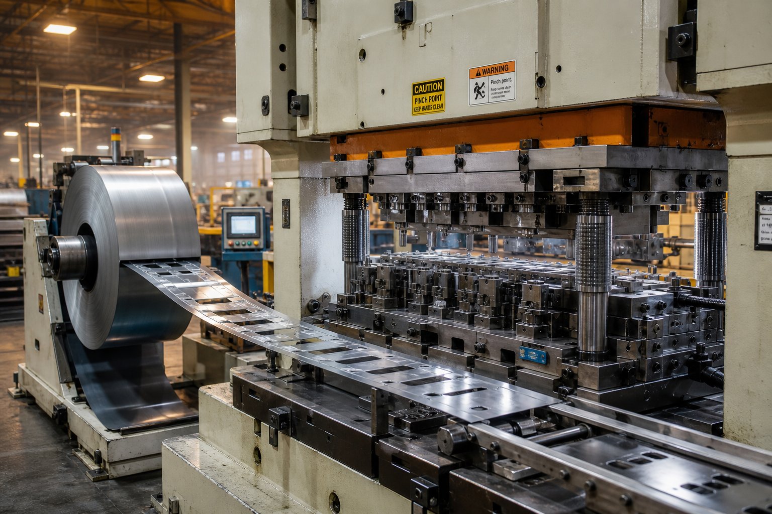
Imagine a flat coil of steel rolling into a press and emerging seconds later as a precisely shaped bracket, terminal, or structural panel. That transformation doesn't happen by accident. Every cut, bend, and form is the result of a carefully orchestrated sequence - and missing even one detail in that sequence can mean scrapped parts, costly rework, or months of delayed production.
What Is Die Stamping and Why Does the Process Sequence Matter
Die stamping is a cold-forming manufacturing process that uses specialized tooling - called dies - mounted inside a press to cut, bend, and shape flat sheet metal into finished components at high speed and with repeatable precision.
So, what is a stamping operation in practical terms? It's far more than a single press hit. The steps for die stamping span two distinct phases that most overviews treat as an afterthought: the engineering and planning phase (part design review, material selection, die design, and die fabrication) and the physical press phase (setup, tryout, production runs, quality verification, and maintenance). Treating these as separate conversations leads to disconnected decisions - a geometry that looks great in CAD but cracks during forming, or a die built without considering long-term maintenance access.
What are dies, exactly? They're precision-machined tool steel assemblies containing punches, die blocks, strippers, and pilots, all engineered to perform specific operations - blanking, piercing, bending, drawing - in a controlled sequence. When every step in the process is aligned, a single progressive die can produce hundreds of identical parts per minute while holding tolerances as tight as ±0.005 inches.
Who Benefits from Understanding Each Step
This guide is built as a decision-making resource, not a glossary. If you're a tooling engineer, you'll find actionable detail on clearance calculations, bypass notch design, and springback compensation. Manufacturing planners will benefit from the sections covering press selection, tonnage requirements, and production monitoring. Product designers, meanwhile, will gain the context needed to evaluate whether stamping fits their application before committing to expensive tooling.
Understanding what is metal stamping at each stage - from the first geometry review through post-production die maintenance - gives every stakeholder the ability to make smarter trade-offs earlier. That's where cost savings, quality gains, and shorter lead times actually originate. The process begins well before metal ever touches a press, and it starts with one critical question: is your part design ready for the demands of die stamping?
Part Design Review and Material Selection
A metal stamped part doesn't begin its life on a press. It begins on a screen - in a CAD model where every wall angle, draw depth, and radius either sets the project up for success or quietly guarantees problems downstream. The pre-production planning phase is where stamping design decisions carry the most leverage, yet it's the stage most often rushed.
Part Geometry Analysis and Die Type Selection
Before any tooling concept takes shape, engineers evaluate the part's geometry against a fundamental question: can this shape actually be formed from flat sheet metal in a repeatable, high-speed process? The analysis focuses on several critical features:
- Wall angles - steep walls (close to 90 degrees) increase friction and require higher forming forces, while shallow angles form more easily but may introduce springback.
- Draw depths - deeper draws demand higher material elongation and more controlled blank holder pressure. Exceeding the material's draw ratio leads to thinning or cracking.
- Radii and transitions - sharp internal corners concentrate stress. Minimum bend radii depend on material type and thickness, typically ranging from 0.5t to 2t (where t equals material thickness).
- Feature spacing - holes, slots, and tabs placed too close to bends or edges risk distortion during forming.
This geometry analysis directly determines which die type fits the application. The three primary options - progressive, compound, and transfer - each serve different levels of complexity and volume:
| Die Type | Best For | Complexity Level | Volume Suitability |
|---|---|---|---|
| Progressive | Complex parts with multiple operations (cuts, bends, forms) | High | High-volume production |
| Compound | Flat parts requiring simultaneous cut-and-form in a single stroke | Low to moderate | Small to medium runs |
| Transfer | Large or deeply drawn parts needing independent station operations | High | Medium to high volume |
A simple flat washer with tight concentricity tolerances? A compound die handles that in one stroke. A multi-feature bracket with pierced holes, formed tabs, and coined embosses? That's progressive die territory, where the strip advances through sequential stations. A deep-drawn automotive cup too large to remain attached to a carrier strip? Transfer dies move the blank independently between stations using mechanical grippers, which also reduces material waste by eliminating the carrying web.
Material Selection and Its Impact on Stamping Steps
Geometry tells you what shape you need. Material tells you whether you can actually get there - and at what cost to tooling life, cycle time, and downstream finishing. Each metal family behaves differently under the forces of sheet metal stamping, and those differences ripple through every subsequent die design decision.
Here's what matters when evaluating materials:
- Tensile strength - determines how much force the press must deliver to cut and form the part. Higher strength means higher tonnage requirements and more robust tooling.
- Elongation - measures how far the material can stretch before fracturing. Critical for draws and complex forms. Low-carbon steel typically offers 25-40% elongation, while some aluminum alloys range from 10-20%.
- Grain direction - sheet metal has a rolling direction from the mill. Bending perpendicular to the grain reduces cracking risk, so part orientation on the strip must account for this.
- Thickness consistency - even small variations in material gauge affect punch-to-die clearance, forming forces, and final part dimensions.
In steel sheet stamping, cold-rolled steel offers controlled surface quality, predictable formability, and cost-effectiveness for high-volume metal stamping components like brackets, clips, and structural panels. Stainless steel adds corrosion resistance but resists forming - it work-hardens quickly, demanding tighter clearances and more frequent tool sharpening. High-strength low-alloy (HSLA) steels, common in stamped steel automotive structures, offer durability but reduced elongation, which limits draw depths.
The aluminum stamping process presents its own trade-offs. Aluminum is lightweight, corrosion-resistant, and highly malleable, making it ideal for enclosures and heat sinks. But it's also softer - meaning galling and material pickup on tooling surfaces becomes a concern. Die coatings and surface treatments become part of the metal stamping design conversation early on.
Copper and brass, meanwhile, offer excellent electrical conductivity and malleability. They form easily but are prone to springback in bending operations, requiring overbend compensation built into the die geometry.
Determining Whether Die Stamping Fits Your Application
Not every part belongs in a stamping die. The planning phase should include an honest assessment of whether the process matches your production reality. Die stamping excels when you need:
- High production volumes (typically thousands to millions of parts) that justify tooling investment
- Repeatable tolerances across long runs without operator-dependent variation
- Complex multi-feature parts that would require multiple setups in alternative processes
- Low per-piece cost once tooling is amortized
When volumes are low (under a few hundred pieces), or when the design is still changing frequently, laser cutting or CNC machining may deliver parts faster and cheaper - no hard tooling required. Laser cutting also handles thicker materials and complex 2D profiles without forming, though it cannot bend or draw material into three-dimensional shapes.
The sequential decisions made during this planning phase follow a clear logic:
- Review part geometry for formability constraints
- Select the material based on functional requirements and forming behavior
- Determine die type based on part complexity and production volume
- Validate that stamping is the right process versus alternatives
- Establish target tolerances and critical dimensions that drive die engineering
Each decision feeds the next. Material choice constrains die clearance calculations. Die type determines strip layout strategy. And all of it shapes the engineering work that follows - where die structure, punch geometry, and station sequencing turn planning decisions into physical tooling.
Die Design and Engineering Considerations
Material has been selected, part geometry has been validated, and the die type has been chosen. The engineering challenge shifts now from what to build to how to build it. Metal stamping die design is where planning decisions become physical tooling - every clearance value, every pilot location, and every station sequence must be resolved before a single block of tool steel is machined. Get this phase right, and the die runs millions of cycles with minimal intervention. Get it wrong, and you'll chase burrs, misfeeds, and cracked parts for the life of the tool.
Die Structure and Component Engineering
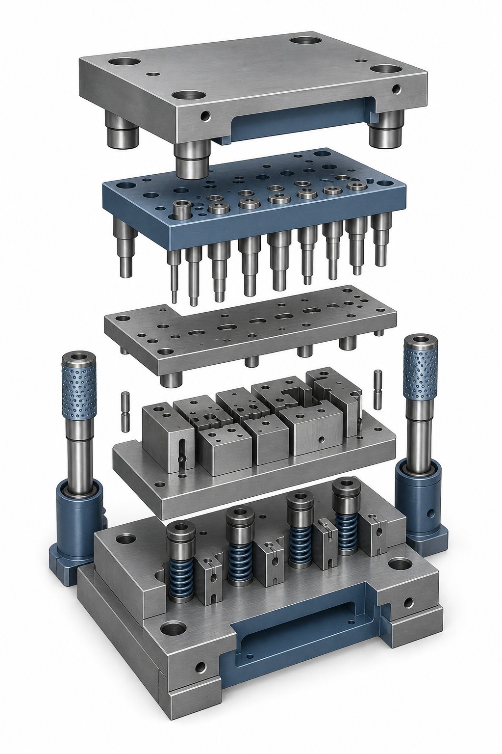
A metal stamping die is an assembly of precision components, each serving a distinct mechanical function. Think of it as a system with three layers: the structural foundation, the guidance system, and the working components that directly contact the material.
The die shoe forms the structural base. Upper and lower die shoes - typically machined from medium carbon steel like S50C - absorb impact forces and provide a rigid mounting surface for all internal components. Guide posts pressed into the lower shoe align with bushings in the upper shoe, ensuring repeatable closure accuracy at high press speeds.
Within that framework, the critical stamping die components include:
- Punches - the upper cutting or forming tools, typically made from high-speed steel (SKH9) or D2 tool steel, heat-treated to HRC 60-62 for wear resistance at the cutting edge.
- Die blocks (inserts) - the lower mating surfaces containing cavities or cutting edges. Clearance between the punch and die block determines edge quality and tool life.
- Stripper plates - spring-loaded plates that hold the strip flat against the die surface during cutting and strip the material off the punch during retraction.
- Pilots - precision pins that engage pre-punched holes in the strip to ensure exact registration at each station.
- Lifters - spring-loaded rails or pins that raise the strip above the die surface between press strokes, allowing the strip to advance freely without dragging across cutting edges or form features.
Lifter design deserves particular attention. If lifters don't raise the strip high enough, formed features can snag on downstream stations. Too high, and the strip may not seat properly against pilots before the next hit. Engineers typically set lifter height to clear the tallest formed feature by 1.5 to 2 mm - enough for reliable advancement without excessive strip whip at high speeds.
Clearance Settings and Strip Layout Optimization
Punch-to-die clearance is one of the most consequential decisions in stamping die design. It's expressed as a percentage of material thickness per side and directly controls edge quality, tool wear rate, and cutting force. Too tight, and the punch experiences excessive friction and premature wear. Too loose, and the cut edge develops heavy burrs and rollover.
General clearance guidelines based on material type:
| Material | Recommended Clearance (per side) | Key Consideration |
|---|---|---|
| Low-carbon steel | 5-8% of thickness | Good balance of edge quality and tool life |
| Stainless steel | 6-10% of thickness | Higher strength requires slightly more clearance to prevent punch galling |
| Aluminum | 4-6% of thickness | Softer material; tighter clearance reduces burr height |
| Copper/Brass | 3-6% of thickness | Highly ductile; tight clearance yields clean shear |
Strip layout optimization, meanwhile, determines how efficiently material is consumed during production. The layout defines the pitch (distance the strip advances per stroke), the strip width, and the arrangement of features relative to the carrier web. According to industry benchmarks, a well-designed layout targets at least 75% material utilization - meaning only 25% or less of the coil becomes scrap.
Key layout decisions include:
- Bridge width - the material left between parts and between parts and strip edges. A common formula uses 1.25t to 1.5t (where t = material thickness) as the minimum bridge to maintain strip integrity.
- Pilot hole placement - punched in the first station, these holes are engaged by pilots in every subsequent station to correct for minor feed inaccuracies. Placing pilots in the carrier web, away from formed features, ensures reliable registration.
- Station sequencing - progressive die stations follow a logical order: pilot holes first, then piercing operations, followed by forming and bending, with final trimming and cutoff at the last station. Idle stations are often included between heavy forming steps to allow die designers room for future engineering changes without rebuilding the entire tool.
Tolerance stacking is a real concern across multiple stations. Each station introduces its own positional variance - pilot engagement tolerance, punch alignment, material springback - and these variances accumulate. Engineers address this by designing tighter pilot clearances (typically 0.01 to 0.02 mm) and concentrating critical features in adjacent stations to minimize cumulative error.
Bypass Notches and Material Flow Control
Sounds like a minor detail? Bypass notches are actually one of the most effective tools for controlling burr formation and material behavior in sheet metal stamping dies. These are small relief cuts - either negative or positive - made at the edges of the strip where adjacent blanking or trimming operations meet.
Here's why they matter: when two cutting operations share a common edge, the slug from one cut can interfere with the adjacent cut, creating excessive burrs or irregular edge conditions. Negative and positive bypass notches in sheet metal stamping dies solve this by creating a controlled separation point between cutting zones. A negative bypass removes a small sliver of material at the junction, while a positive bypass leaves a small tab that is later trimmed. Both approaches ensure clean shear at each station boundary.
Beyond burr control, bypass notches also regulate how material flows into forming stations. By relieving stress at specific points along the strip edge, they allow the metal to draw and stretch without pulling material from adjacent features. This is especially critical in progressive dies where forming stations sit between cutting stations - without proper notching, the strip can twist or buckle during forming.
Springback compensation in forming stations adds another layer of engineering. Materials naturally spring back toward their original shape after bending - stainless steel more so than low-carbon steel, aluminum somewhere in between. Engineers compensate by designing the die to over-bend the part beyond the target angle, allowing elastic recovery to bring it back to specification. The degree of overbend depends on material tensile strength, bend radius, and part geometry, typically ranging from 1 to 5 degrees for most sheet metals.
The interplay between clearance settings, strip layout, bypass design, and springback compensation is what separates a mediocre die from one that runs reliably for millions of hits. For tooling engineers navigating these complex decisions - particularly around die structure, component selection, burr control, and material flow - working with an experienced die partner can significantly reduce development risk. YICHEN's custom stamping die solutions span the full range of these engineering challenges, supporting design-heavy applications where precision across multiple types of stamping dies is non-negotiable.
Engineering the die on paper (or screen) is only half the journey. The true test comes when those designs are translated into hardened tool steel - machined, heat-treated, and assembled to tolerances measured in microns.
Die Fabrication and Assembly
A die design file is just a set of instructions. The die making process transforms those instructions into hardened, ground, and assembled tooling capable of withstanding millions of high-force impacts without losing dimensional integrity. Every micron of error introduced during fabrication shows up later as a defect on the finished part - a burr that shouldn't be there, a hole slightly out of position, a form that doesn't meet print. Precision at this stage isn't aspirational. It's non-negotiable.
Machining and Heat Treatment of Die Components
Fabrication follows a defined sequence, and the order matters. Skipping steps or rushing heat treatment introduces internal stresses that compromise the entire stamping die set. Here's how experienced metal tool and die shops approach the process:
- Rough CNC machining - die blocks, punch holders, and die shoe plates are milled to near-net shape, leaving 0.2-0.5 mm of stock for finishing after heat treatment. This accounts for the slight dimensional changes that occur during hardening.
- Wire EDM - complex punch profiles, die cavity openings, and tight-radius features are cut using electrical discharge machining. Wire EDM achieves tolerances of sub-micron precision on hardened materials, making it essential for intricate stamping tooling geometry that conventional milling can't reach.
- Heat treatment - tool steel components are hardened through controlled heating and quenching cycles. The target hardness depends on the material grade and its role in the die. D2 tool steel (high chromium, high carbon) reaches 58-62 HRC and offers excellent wear resistance for cutting edges. A2 provides a balance of toughness and wear resistance at 57-60 HRC, making it a reliable general-purpose choice. M2 high-speed steel maintains hardness at elevated temperatures, suited for high-speed production where friction generates heat at the cutting edge.
- Precision grinding - after hardening, components are ground to final tolerances, typically ±0.005 mm for working surfaces. Surface grinding establishes flatness on die shoes and backing plates, while cylindrical and profile grinding finishes punch diameters and form contours.
- Surface finishing and coating - polishing reduces friction on forming surfaces (targeting Ra 0.2-0.4 μm), and coatings like TiN or DLC extend life by reducing adhesive wear, particularly important when stamping aluminum or stainless steel.
Material selection for die components directly governs maintenance intervals and total die life. Carbide inserts, for instance, can extend tool life by 500-1000% compared to conventional tool steels in high-volume or abrasive-material applications - but they're brittle. A misaligned hit or excessive shock load can crack a carbide insert instantly. The choice between D2, A2, M2, and carbide is always a trade-off between wear resistance, toughness, and cost relative to production volume and workpiece material.
Assembly Procedures and Bench Verification
With all components machined and hardened, assembly begins on a bench - not in the press. Skilled metal tool and die makers fit each component into the stamping die set methodically, verifying clearances and alignment at every step.
The assembly sequence typically proceeds as follows: guide pins and bushings are installed in the die shoe first, establishing the master alignment reference. Punches are then fitted into retainer plates and checked for perpendicularity. Die inserts and buttons are seated in the lower assembly, and punch-to-die clearance is verified using feeler gauges or calibrated shim stock - confirming that the gap matches the designed percentage per side for the target material.
Lifters are installed and stroke-tested to confirm proper height. Pilots are checked against pre-punched sample strips to verify engagement depth and centering. Strippers are shimmed to establish correct pre-load pressure.
Before the die ever sees a production press, bench-level testing validates component fit. Die makers cycle the tool by hand or with a slow-speed press to confirm that punches enter die openings cleanly, strippers retract without binding, and all moving components clear each other throughout the full stroke. Any interference discovered here is resolved with minimal rework. The same problem discovered during a full-speed production tryout could mean a crashed die and weeks of repair.
This relationship between fabrication precision and downstream part quality is direct and unforgiving. A punch ground 0.01 mm oversize changes the clearance ratio, which changes the burr condition on every part that die produces. A die shoe that isn't flat within 0.005 mm introduces misalignment that accumulates across progressive stations. The discipline applied during fabrication and assembly determines whether the next phase - press setup and tryout - goes smoothly or turns into a troubleshooting exercise.
Press Selection and Die Setup
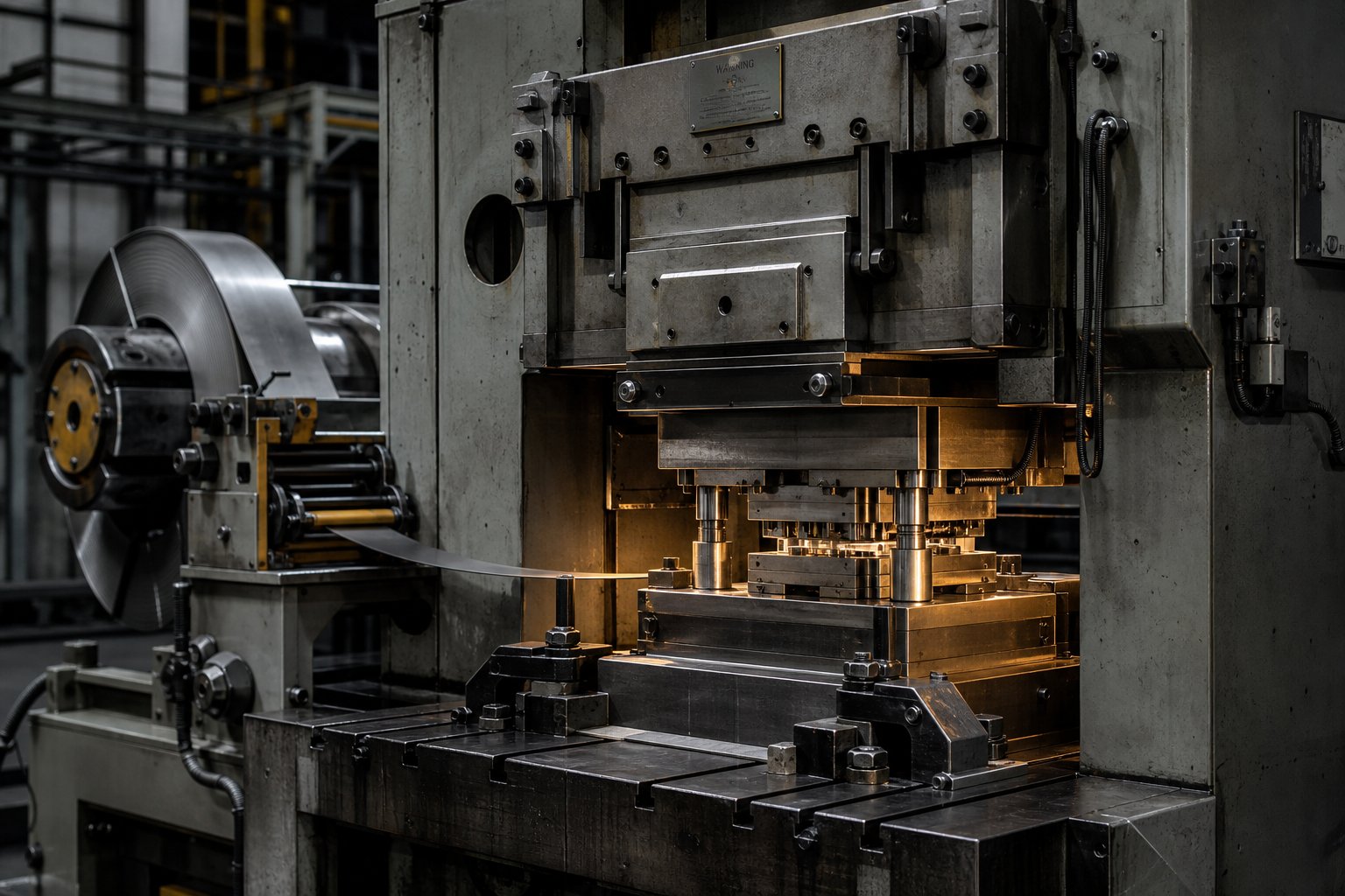
A perfectly engineered die sitting in the wrong press is a recipe for problems - insufficient tonnage causes short hits, an undersized bed deflects under load, and a stroke that doesn't match draw depth produces incomplete forms. Choosing the right die stamping press isn't a catalog exercise. It's a calculation-driven decision that accounts for the specific forces your die will generate, the physical envelope it occupies, and the production speed your schedule demands.
Press Selection and Tonnage Calculations
Every press has a tonnage rating, but that number alone doesn't tell you whether the machine fits your die. You need to calculate the actual load your tooling will apply - and that means reviewing every operation happening at every station in a single press cycle.
The fundamental tonnage formula for blanking and piercing is straightforward:
Required Tonnage = Cut Perimeter (in.) x Material Thickness (in.) x Material Shear Strength (tons/sq. in.)
This formula uses full material thickness to account for dull or worn cutting edges over time. In practice, shearing actually occurs partway through the material - visible as the shear band on any stamped edge - so sharp tooling reduces the actual load. Putting shear angles on punch faces can further reduce cutting force by up to 30-40%, distributing the load over a longer portion of the press stroke.
For drawing operations, the calculation shifts from shear strength to ultimate tensile strength, because the material is in tension rather than being sheared:
Drawing Tonnage = Draw Perimeter (in.) x Material Thickness (in.) x Ultimate Tensile Strength (tons/sq. in.)
But cutting and drawing forces are only part of the story. A complete tonnage calculation for a progressive die must also include blank holder pad pressure, spring stripper forces, strip lifter pin resistance, nitrogen pressure pads, driven cams, and any scrap cutters. Add these together across all stations - that's your total required press tonnage.
Beyond tonnage, you'll need to verify two additional factors. First, the press must deliver enough energy to complete the work. Tonnage capacity without sufficient flywheel energy causes the press to stall at bottom dead center - a common cause of jams in high-strength material applications. Second, the load distribution across the press bed matters. The press tonnage rating assumes the die load is equally distributed over two-thirds of the bed area. A small die stamping machine with an oversized bed may deflect unevenly if the load concentrates in a narrow zone.
Bed size requirements follow directly from die dimensions plus clearance for bolster plates, clamps, and feed equipment. Stroke length must exceed the die's draw depth plus clearance for strip lift and part ejection. For a die with a 25 mm draw, you'll typically need a stroke at least 50-75% longer than the draw depth to allow full material clearance during strip feeding.
Speed requirements tie back to your production targets. A die stamping press running at 200 strokes per minute produces twice the output of one running at 100 - but only if the material can flow, form, and eject cleanly at that speed. Deeper draws and complex forms demand slower slide velocity at the working portion of the stroke, which is where press type selection becomes critical.
| Press Type | Key Characteristics | Best Applications | Speed Range (SPM) |
|---|---|---|---|
| Mechanical | Fixed stroke length; full capacity near BDC; high repeatability; simple operation | Flat or shallow-formed parts; high-speed blanking; automatic stamping lines | 100-1500+ SPM |
| Hydraulic | Variable stroke length; full tonnage anywhere in stroke; dwell capability | Deep draws; complex forming; low-to-medium volume; heavy-gauge pressing and stamping | 10-60 SPM |
| Servo-Mechanical | Programmable stroke profiles; variable speed within cycle; full energy at any speed | Complex parts requiring speed flexibility; mixed die types; high-quality forming with production-level throughput | 20-250+ SPM (profile-dependent) |
A traditional mechanical press achieves the highest production speeds for relatively flat parts with simple forming. Hydraulic presses sacrifice speed but deliver full tonnage and energy through the entire stroke - essential for deep, complex forms where material needs time to flow. Servo presses combine the versatility of hydraulic with speeds approaching mechanical, making them increasingly common in shops running diverse metal press dies across multiple part families.
For small stamping press operations - prototyping shops or low-volume production - a smaller-tonnage servo or hydraulic press offers the flexibility to run varied tooling without committing to a dedicated high-speed line. Larger operations focused on automatic stamping typically invest in mechanical presses paired with high-speed coil feeding systems to maximize throughput.
Die Setup Alignment and Calibration
With the press selected, setup begins. This phase bridges engineering theory and physical reality - the die must be mounted, aligned, and calibrated so that every stroke replicates the conditions assumed during design.
The setup sequence follows a logical order:
- Mounting the die - the die is positioned on the press bolster and secured using T-slot clamps or hydraulic clamping systems. Alignment starts here: the die's feed direction must run parallel to the coil feed line, and the die centerline should be positioned relative to the press centerline to balance off-center loading. Contrary to common practice, positioning the die as close as possible to the feeder isn't always optimal - centering based on calculated load moments often produces better die and press balance.
- Guide pin engagement - as the ram descends slowly, guide pins in the die shoe engage their corresponding bushings. Technicians verify smooth engagement with no binding or lateral play that would indicate misalignment between upper and lower assemblies.
- Shut height adjustment - the ram is lowered until the die fully closes against its solid stops or calibration blocks. This is the die's shut height, and the press ram must be set precisely to this dimension. Too high, and forming operations won't complete. Too low, and the die is over-driven - potentially cracking punches or deforming die blocks.
- Feed progression setting - the coil feeder is programmed to advance the strip a distance equal to one progression (the centerline distance between die stations). Many die designers build a solid stop into the first station as a reference point, which helps eliminate misinterpretation of the correct feed distance and prevents overfeeding that can damage the die.
- Pilot engagement verification - this is where timing becomes critical. The feeder must release the strip at precisely the right moment in the press stroke so that pilot pins can engage and register the strip before full closure. Release too late, and the pilots fight against clamped material - breaking or galling. Release too early, and the weight of the strip loop between the feeder and die can pull the material out of position.
Setting the pilot release point requires inching the press down until the bullet nose of each pilot just begins to enter its hole. At that exact position - measured in degrees of crank rotation - the feeder is programmed to unclamp the strip. The strip remains unclamped through the working portion of the stroke and is re-clamped only after lifters have raised it back to feeding level. Getting this timing wrong causes misfeed, elongated pilot holes, bent or broken pilots, and poor part registration across all stations.
Die Tryout and Initial Validation
Setup is complete, but the die hasn't proven itself yet. The tryout phase is where the first real parts are made - cautiously, at reduced speed, with every aspect of the process under scrutiny.
Initial hits are taken one stroke at a time using the press inching mode. The technician feeds the strip forward one progression and cycles the press through a single complete stroke. At this stage, you're watching for:
- Strip advancement - does the material feed exactly one progression? Are pilot holes engaging cleanly without elongation?
- Part formation - are forms and bends achieving the correct geometry? Is there evidence of cracking, wrinkling, or incomplete forming?
- Scrap removal - are slugs dropping cleanly through die openings? Retained slugs are a top cause of die damage during tryout.
- Lifter function - does the strip rise above all formed features between strokes, allowing smooth linear feed without snagging?
The first several parts may not meet dimensional specifications - and that's expected. With the strip fully threaded through all stations, the die reaches its steady-state condition where all spring forces and forming pressures are balanced. Technicians then perform a stop-block reading to confirm the die is fully closing under load. Heavy-gauge or high-strength materials can cause the press to gap or deflect, meaning the ram may need to be lowered slightly beyond the nominal shut height to achieve proper deformation.
Speed is increased gradually - from single strokes to slow continuous operation, then stepped up toward production rates. At each speed level, stamping press parts are checked dimensionally and visually. Slide velocity limitations at draw stations may cap the maximum achievable speed, particularly on parts with deep forms where the material needs time to flow without tearing.
A successful tryout confirms that the die, the press, and the feed system work as a coordinated unit. The transition from validated tryout to full production introduces the final variable: sustained volume - where strip feeds continuously, sensors monitor every stroke, and the real test of tooling quality begins.
Production Stamping Operations Step by Step
Tryout confirmed the die produces good parts at controlled speed. Production is a different animal. The press runs continuously, coil feeds without pause, and every stroke must replicate the same result - hundreds or thousands of times per hour, shift after shift. Understanding what physically happens during each stage of the metal stamping process gives operators and engineers the insight to maintain quality at speed and respond quickly when something drifts.
Coil Feeding and Strip Progression Through Stations
The sheet metal stamping process begins at the uncoiler. A steel or aluminum coil - often weighing several thousand pounds - sits on a mandrel that pays material into the line at a controlled rate. Between the uncoiler and the press, a straightener uses a series of offset rollers to remove the coil set (the natural curvature from being wound). Without proper straightening, residual curvature causes the strip to lift unevenly off lifters, misalign against pilots, and produce inconsistent forms.
From the straightener, the strip enters a servo roll feeder or gripper feeder that advances it by exactly one progression per press stroke. Timing is everything here. The feeder clamps the strip and pushes it forward during the non-working portion of the press cycle - while the ram is ascending and the die is open. As the ram descends, the feeder releases the strip so pilot pins can engage and make final positional corrections before the working tools contact the material.
A loop control system between the straightener and feeder maintains a slack loop of material. This loop acts as a buffer, decoupling the intermittent pull of the feeder from the continuous unwind of the coil. Sensors monitor loop depth - if the loop tightens, the uncoiler speeds up; if it sags too far, the uncoiler slows. This keeps consistent tension on the strip without starving or overfeeding the press.
Blanking Piercing Forming and Trimming Operations
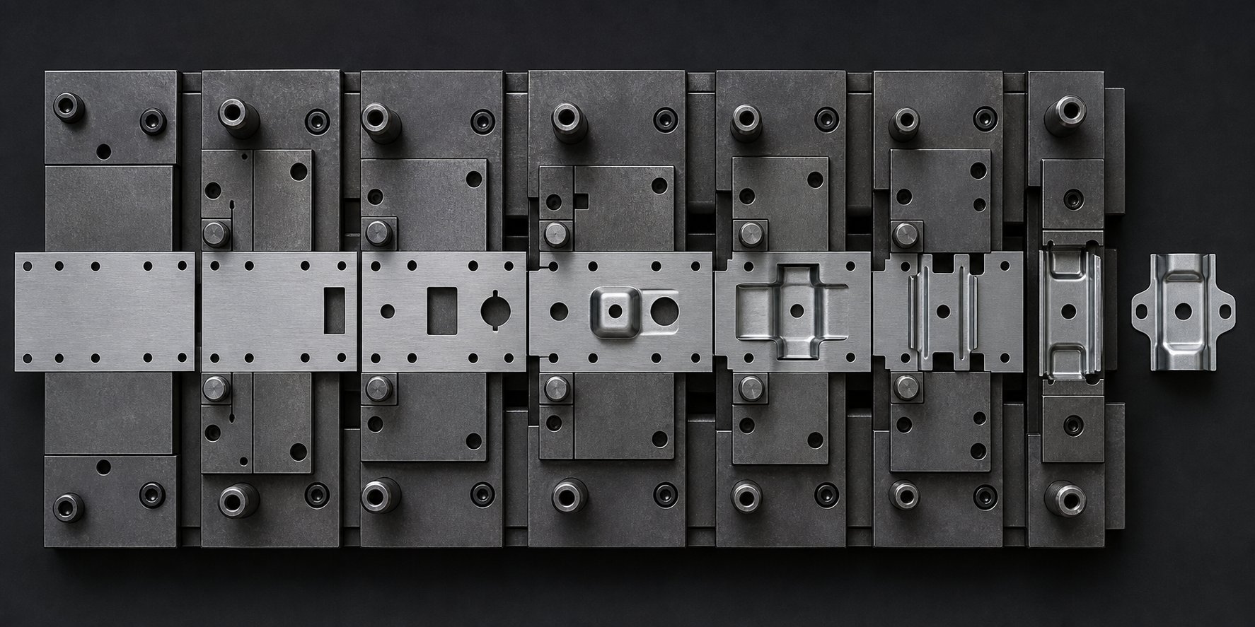
Once the strip reaches the die, it passes through a sequence of stations - each performing a single operation or a small group of related operations. In a progressive die stamping process, the strip stays connected to a carrier web throughout, advancing one pitch per stroke until the finished part is separated at the final station.
Here's what happens mechanically at each stage:
- Pilot hole piercing - the first station punches small round holes in the carrier portion of the strip. These holes serve no function on the finished part. They exist solely to provide a registration reference for pilots in every downstream station.
- Blanking and initial piercing - functional holes, slots, and peripheral features are cut. During stamping blanking operations, punches shear through the material and push slugs into die openings where they fall through relief holes into a scrap chute below. The shear action produces a characteristic edge profile: a small rollover at entry, a clean shear band through roughly one-third of the thickness, and a fracture zone with slight burr at breakaway.
- Forming and drawing - punches push material into die cavities, creating bends, ribs, embosses, or drawn cups. Unlike cutting operations that rely on shear, forming stations apply compressive and tensile forces that plastically deform the metal without separating it. Blank holder pads or nitrogen springs apply controlled pressure to prevent wrinkling during draws.
- Secondary piercing - holes or features that must be located relative to formed geometry are punched after forming rather than before. Punching before forming would distort hole positions as surrounding material shifts during the draw or bend.
- Trimming and cutoff - excess carrier material is trimmed from the part perimeter. The final station separates the finished part from the strip entirely, either by cutting the last connecting tabs or shearing across the full width. The completed part drops through the die into a collection bin or onto a conveyor, while the remaining skeleton scrap exits the back of the press.
Each punching stamping and forming operation adds mechanical load to the press. Station sequencing is carefully arranged so that heavy cutting operations don't all occur on the same side of the strip, which would create an off-center load and accelerate guide pin wear. Designers stagger operations across left and right sides of the strip to balance forces as symmetrically as possible.
Transfer die stamping differs from progressive in one fundamental way: the part is physically separated from the strip at the first station (blanked out as an individual piece), then moved between subsequent stations by mechanical fingers, grippers, or rails. This makes transfer stamping well-suited for larger parts or deeply drawn geometries that can't remain attached to a carrier strip - imagine trying to carry a 200 mm deep cup through six progressive stations while still connected to a flat strip. The trade-off is speed. Transfer operations run slower because the mechanical transfer system needs time to pick, move, and place each blank between strokes. Transfer die stamping also demands more sensors per station to confirm that parts have been properly positioned before the press closes.
Production Monitoring and Die Protection Systems
Running a die at production speed means trusting that hundreds of mechanical events happen correctly every second. That trust needs verification - and modern stamping lines use layered monitoring systems to catch problems before they cause damage.
Hit counters track total strokes on the die. This number drives maintenance scheduling - when the counter reaches a predetermined threshold (say, 250,000 hits), the die is pulled for inspection, sharpening, or component replacement regardless of whether visible problems have appeared. Hit counters also log total die life, helping engineers predict when a full rebuild will be needed.
Feed accuracy sensors - typically proximity or photoelectric types - verify that the strip has advanced the correct distance before each stroke. The sensor monitors whether the strip's pilot holes align with expected positions. If the strip is short-fed or over-fed beyond the pilot's ability to correct, the sensor signals the press to stop immediately. As die protection specialists note, sensor tolerances should match the die's actual pilot correction range rather than being set unnecessarily tight - overly sensitive settings cause nuisance stops that erode operator confidence in the system.
Part ejection sensors confirm that finished parts and scrap slugs have exited the die before the next stroke. A retained slug sitting on top of a die opening will be driven into the cutting edge on the next hit, damaging both the punch and die insert. Ejection sensors typically use brief timing windows - the part must pass the sensor within a specific number of degrees of crank rotation, or the press halts.
Stripper and cam-return sensors verify that moving die components have returned to their home positions before the strip advances. A cam that fails to retract, or a stripper that hangs up, will collide with the advancing strip and cause a catastrophic crash.
Modern die protection controllers tie all these sensor inputs together, monitoring them against timing windows referenced to crankshaft position (typically resolved to one-third of a degree). The controller stores unique setup parameters for each die, so switching jobs doesn't require re-programming sensor logic from scratch.
Production speed optimization ultimately balances throughput against these monitoring constraints. A simpler part with shallow forms and basic piercing might run at 400-800 strokes per minute on a high-speed mechanical press. A complex part with deep draws, multiple forming stations, and tight dimensional requirements may be limited to 60-150 strokes per minute - not because the press can't go faster, but because material flow and sensor verification need time. Cycle time is a direct reflection of part complexity, and pushing speed beyond the process's natural limit shows up quickly as defects, sensor faults, or die damage.
Sustained production at the right speed, with sensors confirming every critical event, is what separates reliable stamping from reactive firefighting. But even well-monitored lines produce parts that need verification - and when dimensions drift or surface defects appear, knowing exactly where to look and what to adjust makes the difference between a five-minute correction and a full production shutdown.
Quality Control and Defect Troubleshooting
A stamping die can run at 300 strokes per minute, producing parts that look identical to the naked eye. But "looks right" isn't a quality standard. Dimensional drift, edge degradation, and forming inconsistencies develop gradually - often invisibly - until a batch of stamped components fails at assembly or in the field. Effective quality control in metal sheet stamping catches those trends early, and effective troubleshooting traces them back to a correctable root cause rather than treating symptoms.
Inspection Methods During and After Stamping
Quality verification in stamping metal parts operates in layers, each designed to catch different types of variation at different points in the process.
First-article inspection happens before full production begins. After die setup and tryout, the first several parts are pulled and measured against the engineering drawing - every critical dimension, every tolerance callout. This confirms that the die, press, and feed system are producing parts within specification before hundreds or thousands of additional pieces are made. If first-article parts fail, production doesn't start.
In-process inspection catches drift during the run. Operators pull sample parts at defined intervals - commonly every 500 to 2,000 hits depending on criticality - and check key features using go/no-go gauges, calipers, or optical comparators. For stamped sheet metal parts with complex geometry, coordinate measuring machines (CMMs) verify hole positions, bend angles, flatness, and profile accuracy against 3D models. CMMs are particularly valuable for progressive die work where positional accuracy of features across multiple stations is critical to function.
Statistical Process Control (SPC) adds a predictive dimension. Rather than just checking whether individual parts pass or fail, SPC tracks measurement data over time on control charts. You'll notice trends - a hole diameter slowly growing as a punch wears, or a bend angle drifting as forming surfaces degrade - before any single part actually exceeds tolerance. That early warning gives operators time to schedule maintenance or adjust parameters without scrapping product.
Visual inspection targets surface defects that gauges can't quantify: scratches, galling marks, dents from retained slugs, die marks from contamination, and cosmetic blemishes that affect appearance-critical stamped components. For burr-sensitive applications, burr height is measured with a depth gauge or surface profilometer against a maximum allowable specification - often 0.05 to 0.10 mm for precision metal parts stamping.
Final inspection before shipment confirms that parts meet all drawing requirements and customer-specific criteria. This may include functional checks - verifying that clips engage, tabs align with mating features, or drawn cups seat properly in assemblies.
Common Defects and Root Cause Troubleshooting
When inspection reveals a problem, the question becomes: what changed? Stamping forming issues rarely appear without a triggering event - tool wear reaching a threshold, material lot variation, a press parameter shifting, or lubrication breaking down. The table below maps the most common defects to their likely causes and corrective actions, giving engineers a structured starting point for diagnosis.
| Defect | Visual Symptoms | Likely Causes | Corrective Actions |
|---|---|---|---|
| Burring | Raised sharp edges on cut perimeters; excessive rollover on hole edges | Worn or chipped cutting edges; incorrect punch-to-die clearance; tool misalignment; material thickness variation | Sharpen or replace worn punches; verify and reset clearance per material spec (5-8% for mild steel); check alignment of upper and lower die assemblies |
| Wrinkling | Waves, folds, or buckled areas on flanges, walls, or unsupported surfaces | Insufficient blank holder pressure; poor draw bead design; excessive material flow into cavity; blank too large for the geometry | Increase blank holder force; add or modify draw beads; reduce blank size; improve die surface contact in compression zones |
| Cracking / Splitting | Fractures at bend radii, drawn walls, corners, or high-strain zones | Excessive draw ratio; too-small punch or die radius; poor material ductility; incorrect grain orientation; insufficient lubrication | Increase forming radii; select material with higher elongation; orient blanks perpendicular to grain; improve lubrication; split severe forms into multiple stages |
| Springback | Incorrect bend angles; poor flatness; dimensional deviation after forming | Elastic recovery inherent to material; high yield strength; large bend radius relative to thickness; insufficient forming force | Overbend by 1-5 degrees depending on material; add coining or restriking stations; reduce bend radius where possible; use bottoming instead of air bending |
| Misalignment (holes/features) | Holes, slots, or formed features shifted from nominal position | Pilot wear or damage; feed pitch errors; strip slippage; coil camber; worn guide components; feeder timing mismatch | Inspect and replace worn pilots; verify feed length against die progression; check feeder release timing; correct strip tracking; tighten guide rail clearances |
| Scratches / Galling | Linear marks on part surfaces; material buildup on die forming surfaces | Insufficient lubrication; rough die surfaces; debris in die; tool coating wear; material sensitivity (aluminum, stainless) | Clean and polish die surfaces; reapply or upgrade lubricant; apply TiN or DLC coatings to forming tools; remove debris between runs |
The troubleshooting logic behind this table follows a consistent pattern. When you encounter a defect, start by asking: is this new, or has it been worsening gradually?
A sudden onset - parts were fine on the last run and now they're not - points to a discrete event. Something changed between runs: a new coil with different properties, a die component that cracked, a setup parameter entered incorrectly, or a press condition (tonnage, shut height) that shifted. Check the obvious first. As die troubleshooting experts note, verifying that setup parameters match the documented control plan should always precede any tool modifications.
A gradual degradation - burrs growing taller over thousands of hits, or dimensions drifting toward tolerance limits - indicates wear. Cutting edges dull, forming surfaces roughen, pilots lose diameter, and springs fatigue. SPC charts reveal these trends clearly, and the corrective action is maintenance: sharpen, polish, replace, or regrind the affected component.
One subtlety that catches even experienced engineers: interactivity between defects. Wrinkling in a draw station doesn't just create cosmetic folds - those folds resist material flow into adjacent areas, which can cause splitting somewhere else entirely. Fixing the split without addressing the upstream wrinkling just relocates the problem. Similarly, bypass notches that wear unevenly can create localized burr formation in stamping operations at station boundaries, where the root cause isn't punch wear but degraded strip edge condition entering the next cutting station.
The most effective troubleshooting approach combines inspection data (what exactly is wrong and where), process history (what changed recently), and non-destructive experimentation (testing a hypothesis - like reducing blank size or adding lubricant - before making permanent tool changes). Permanent modifications to hardened tooling should only happen after data confirms the corrective theory. Otherwise, you risk solving one problem while creating another that's harder to reverse.
Quality control and defect resolution keep parts within specification during the production run. But a die's life extends far beyond a single run - and what happens between runs, after the press stops, determines whether the tool delivers consistent results across its full service life or deteriorates into a maintenance burden.
Post-Stamping Operations and Die Maintenance
Stamped metal parts rarely leave the press ready for final use. The cut edges may carry burrs that interfere with assembly, the base material may lack corrosion resistance for its end environment, and the mechanical properties might not yet meet specification. Secondary operations bridge that gap - transforming raw stamping parts into finished components. Meanwhile, the stamping die itself needs structured care between runs to maintain the precision it delivered on day one.
Post-Stamping Secondary Operations
What happens after a part drops out of the die depends entirely on its application. A simple internal bracket may need nothing more than tumble deburring. A connector terminal destined for a humid environment may require selective plating. An automotive structural panel may need heat treatment to reach target hardness. Common secondary operations for stamped metal parts include:
- Deburring - tumbling, vibratory finishing, or manual grinding to remove sharp edges left from cutting operations. Critical for parts that will be handled or assembled by hand.
- Plating and coating - zinc plating, nickel plating, tin plating, powder coating, or e-coating applied for corrosion resistance, conductivity, solderability, or appearance.
- Heat treatment - processes like annealing (to relieve work hardening after severe forming), case hardening, or tempering to achieve specific mechanical properties the base material can't provide in its as-stamped condition.
- Welding and assembly - spot welding, laser welding, or hardware insertion to join stamped components into sub-assemblies before they ship to the customer.
- Cleaning - removing stamping lubricants, metal fines, and residue that would interfere with plating adhesion or downstream processes.
The choice of secondary operations should inform die design decisions early in the process. For instance, if a part requires post-plating, the die engineer needs to account for plating thickness (typically 5-25 microns) when setting hole tolerances and mating feature dimensions. Parts destined for heat treatment may experience slight warping, so critical flatness features might need a restrike station added to the die rather than relying solely on post-process correction.
Die Maintenance and Regrinding Schedules
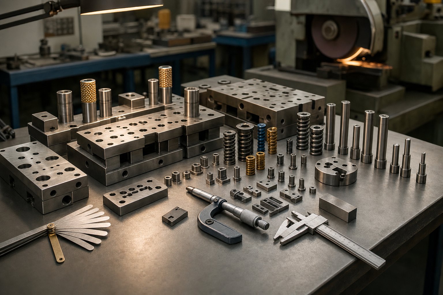
A stamping die is a precision instrument subjected to extreme repetitive forces. Without planned maintenance, even high-quality steel stamping dies and aluminum stamping dies degrade predictably - cutting edges dull, springs fatigue, guide surfaces wear, and clearances open up. The result is gradual quality loss that SPC charts will eventually flag, but proactive maintenance catches before any part fails inspection.
Regrinding schedules are driven by hit counts rather than calendar dates. The logic is straightforward: a die running 500,000 hits per month wears faster than one running 50,000. According to maintenance best practices, cutting edges typically require sharpening every 100,000 to 250,000 strokes depending on material hardness and die steel grade. DC53 and tungsten carbide tooling extends these intervals significantly compared to standard D2 inserts.
A practical stamping die maintenance checklist - applicable across progressive, transfer, and compound tooling - covers these actions at each scheduled interval:
- Clean all scrap paths, slug relief holes, and debris traps
- Inspect cutting edges for wear, chipping, or rounding (sharpen when edge wear exceeds 0.1 mm)
- Check springs for cracks and loss of free length (replace if length drops more than 10%)
- Lubricate guide pins, bushings, and cam surfaces with precision oil
- Verify pilot diameter and engagement condition (replace worn or bent pilots)
- Torque-check all fasteners, especially near high-impact stations
- Inspect stripper plates for wear marks, scoring, or uneven contact
- Measure punch-to-die clearance at critical stations using feeler gauges
- Record hit count, maintenance actions taken, and components replaced
- Run first-off validation parts and confirm dimensional stability before releasing to production
Tracking die life means more than logging total strokes. Effective records capture sharpening history, component replacement frequency, defect correlation, and downtime events per die. Over time, this data reveals which stamping dies in your shop are predictable performers and which ones repeatedly demand unplanned attention - a signal that the underlying design may need revision rather than another round of reactive repair.
This is where stamping die maintenance connects back to initial engineering decisions. A die designed with accessible components, modular insert blocks, and adequate material choices for the application makes routine service fast and predictable. A die built with marginal clearances, hard-to-reach fasteners, or undersized springs creates maintenance headaches for its entire service life. The maintenance plan, in other words, should start at the design stage - not after the first production problem.
Automotive stamping dies face particularly demanding maintenance requirements due to high volumes, tight tolerances, and strict quality systems like IATF 16949. In these environments, preventive maintenance isn't optional - it's a documented process audited alongside production output.
Partnering with Experienced Die Suppliers for Long-Term Success
The steps for die stamping covered throughout this guide - from geometry analysis and material selection through die engineering, fabrication, production, quality control, and maintenance - form an interconnected system. A decision made during strip layout optimization affects maintenance access years later. A clearance setting chosen during die design determines how frequently regrinding is needed in production. The entire lifecycle is linked.
For tooling engineers managing that full lifecycle, working with a die supplier who understands these connections across every phase reduces risk and total cost of ownership. YICHEN's custom stamping die solutions span die structure and component design, burr control, clearance optimization, and the long-term maintenance considerations that keep tooling productive well beyond initial tryout. When the complexity of your application demands expertise that covers design through sustained production support, that kind of lifecycle partnership is worth evaluating.
Frequently Asked Questions About Die Stamping Steps
1. What are the main steps in the die stamping process?
The die stamping process follows a structured sequence: part geometry analysis and material selection, die type determination (progressive, transfer, or compound), die design and engineering with clearance calculations, die fabrication using CNC machining and heat treatment, press selection based on tonnage requirements, die setup and tryout validation, full production with sensor-based monitoring, quality inspection using SPC and CMM, and ongoing die maintenance with scheduled regrinding. Each step directly influences the next, so decisions made early in the planning phase affect tooling performance throughout its entire service life.
2. How do you calculate the required press tonnage for die stamping?
Press tonnage for blanking and piercing is calculated by multiplying the total cut perimeter (inches) by material thickness (inches) by the material's shear strength (tons per square inch). For drawing operations, substitute ultimate tensile strength for shear strength since the material is in tension rather than being sheared. A complete tonnage estimate for a progressive die must also add blank holder pad pressure, spring stripper forces, lifter pin resistance, nitrogen pad forces, and scrap cutter loads across all active stations in a single press cycle.
3. What is the difference between progressive, transfer, and compound stamping dies?
Progressive dies keep the part attached to a carrier strip as it advances through multiple stations, making them ideal for complex, high-volume parts with piercing, forming, and trimming operations. Transfer dies separate the blank from the strip at the first station and move it between stations using mechanical grippers, which suits large or deeply drawn parts that cannot stay connected to a strip. Compound dies perform simultaneous cutting and forming in a single stroke, best for simpler flat parts like washers that need tight concentricity at lower production volumes.
4. What causes burrs in die stamping and how do you fix them?
Burrs in die stamping primarily result from worn or chipped cutting edges, incorrect punch-to-die clearance, tool misalignment, or material thickness variation exceeding design assumptions. Corrective actions include sharpening or replacing dull punches, verifying clearance matches the material specification (typically 5-8% of thickness per side for mild steel), and checking alignment between upper and lower die assemblies. Bypass notch wear at station boundaries can also create localized burr formation, where the root cause is degraded strip edge condition rather than punch wear itself.
5. How often should stamping dies be maintained and reground?
Stamping die maintenance schedules are driven by hit counts rather than calendar dates. Cutting edges typically require sharpening every 100,000 to 250,000 strokes, depending on workpiece material hardness and die steel grade. Carbide tooling and premium steels like DC53 extend these intervals significantly. Each maintenance cycle should include cleaning scrap paths, inspecting springs for fatigue, verifying pilot condition, checking punch-to-die clearance, and running first-off validation parts before releasing the die back to production. Tracking sharpening history and component replacement frequency helps predict when full rebuilds become necessary.


