


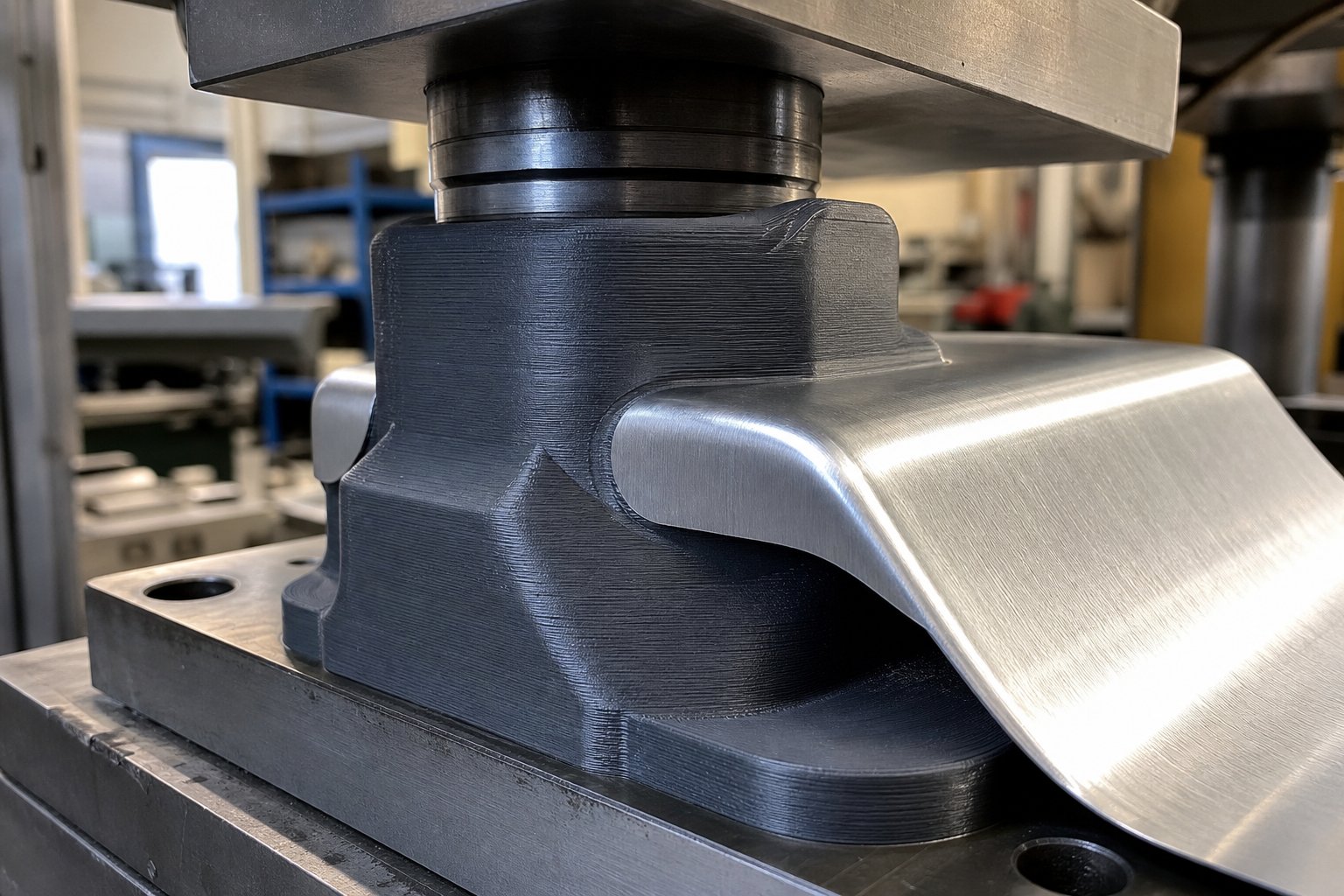
3D Printed Stamping Dies Explained
Imagine needing a custom forming tool for a sheet metal part, but the quote for a CNC-machined steel die comes back at thousands of dollars and weeks of lead time. For a prototype run of 20 parts, that math rarely works. This is exactly where 3D printed stamping dies fit in.
3D printed stamping dies are additive-manufactured tooling components - punches, die blocks, or form tools - used to shape sheet metal through pressing force, produced via layer-by-layer fabrication rather than traditional CNC machining of tool steel.
These tools won't replace hardened steel dies on a 500,000-part production line. But for prototyping, design validation, and short runs, they eliminate the cost and lead-time barriers that keep forming operations locked behind high minimum investments. Research into FDM-based tooling for sheet metal forming confirms that additive manufactured forming tools offer significant cost advantages for single-piece and small-batch production compared to conventional metalworking methods.
What Are 3D Printed Stamping Dies
At their core, these are functional die components printed from engineering plastics, resins, or sintered metals. They mount in a hydraulic press or arbor press just like conventional tooling. The difference is fabrication method: instead of removing material from a steel billet, you build the die geometry layer by layer from a CAD file. This makes 3D printed dies for prototyping fast to iterate and inexpensive to replace when a design changes.
Who Benefits From Printed Tooling
The user base spans a wide range:
- Product designers validating formed sheet metal geometries before committing to production tooling
- Prototyping teams that need functional metal parts on a timeline measured in days, not months
- Low-volume manufacturers producing 10 to 500 parts where traditional tooling costs never amortize
- Hobbyists and small shops running hydraulic or arbor presses for custom brackets, enclosures, and formed components
This guide covers 3D printed stamping dies for sheet metal across every major printing technology and material class. It is technology-agnostic - no single printer brand or material supplier gets favored treatment. You will find honest coverage of both capabilities and limitations, including the low volume stamping die alternatives that make sense and the scenarios where they fall short.
The real question isn't whether printed dies work. It's which technology, material, and design approach matches your specific forming requirements - and that starts with understanding the printing process itself.
Choosing the Right 3D Printing Technology for Dies
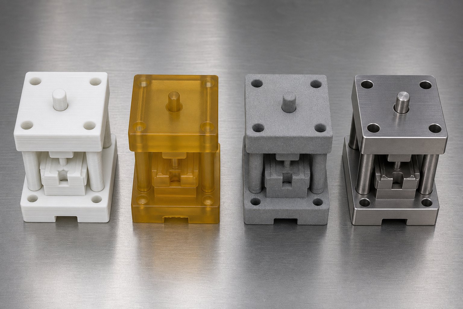
Each printing process builds a die differently at the molecular level, and that directly shapes how the tool performs under press force. A die printed with fused filament won't behave like one cured from liquid resin or sintered from metal powder. The best 3d printing technology for stamping dies depends entirely on what you're forming, how many parts you need, and how much force the operation demands.
Here's a practical 3d printing technology comparison for tooling across the four main process families.
FDM Dies for Low-Force Forming
Fused Deposition Modeling (FDM) is the most accessible entry point. A desktop machine extrudes thermoplastic filament layer by layer, building die geometry in hours for a few dollars in material. The tradeoff? Layer lines create a visible stair-step texture on forming surfaces, and the bonding between layers is always weaker than the material itself. This anisotropy matters because forming forces often load the die perpendicular to layer planes.
FDM dies work well for simple bends and low-force forming in thin aluminum or brass. You'll notice they perform best when compressive loads are distributed over a large area rather than concentrated at sharp edges. When comparing FDM vs SLA for forming dies, the main FDM advantage is cost and speed of iteration. The main disadvantage is surface finish and dimensional tolerance, which typically lands around +/- 0.3 to 0.5 mm depending on the printer and material.
SLA and SLS for Precision Die Applications
Stereolithography (SLA) cures liquid resin with light, producing dies with smooth surfaces and much tighter tolerances than FDM. Formlabs' research into SLA-printed forming tools demonstrated that rigid resin dies can withstand substantial press forces when properly designed, with the smooth surface finish eliminating the polishing step that metal dies sometimes require. SLA parts are also isotropic, meaning strength doesn't change dramatically with build orientation. This makes them a better choice than FDM when forming forces come from multiple directions.
Selective Laser Sintering (SLS) fuses polymer powder in a heated bed. Because unfused powder supports the part during printing, SLS dies can incorporate complex geometries without sacrificing structural integrity. SLS printed die dimensional accuracy typically sits around +/- 0.1 to 0.3 mm, and the resulting nylon parts offer excellent toughness and impact resistance. The surface has a slightly grainy texture from the powder, but it's more uniform than FDM layer lines and transfers less visible marking to formed parts.
Metal Sintering for High-Load Requirements
When forming forces exceed what any polymer can handle, metal sintered dies for sheet metal stamping become the path forward. Selective Laser Melting (SLM) and Direct Metal Laser Sintering (DMLS) produce fully dense metal dies from aluminum, stainless steel, or tool steel powders. These dies can withstand the same forces as machined tooling, with the added benefit of internal cooling channels or weight-reducing lattice structures that conventional machining can't produce.
Metal-printed dies cost significantly more and require post-processing such as stress relief, depowdering, and often machining of critical surfaces. They make sense for geometries that are expensive to machine conventionally, or where conformal features justify the process burden.
| Technology | Dimensional Tolerance | Surface Finish | Max Forming Force | Cost Per Die | Best Use Case |
|---|---|---|---|---|---|
| FDM | +/- 0.3 - 0.5 mm | Visible layer lines (rough) | Low (under 5 kN typical) | $5 - $50 | Simple bends, early prototyping, thin soft metals |
| SLA | +/- 0.1 - 0.2 mm | Smooth (minimal post-processing) | Moderate (5 - 50 kN depending on resin) | $30 - $150 | Precision forms, compound bends, short production runs |
| SLS | +/- 0.1 - 0.3 mm | Slightly grainy (powder texture) | Moderate to high (10 - 80 kN with nylon) | $80 - $300 | Durable tooling, complex geometry, repeated use |
| Metal Sintering (SLM/DMLS) | +/- 0.05 - 0.2 mm | As-built rough; machined to spec | High (limited by design, not material) | $500 - $5,000+ | High-tonnage forming, production-intent tooling, complex internal features |
The pattern is straightforward: as force requirements and part count increase, you move from FDM through SLA and SLS toward metal. But the decision isn't purely about load capacity. A die that needs to produce parts with tight dimensional control and clean surfaces might justify SLA even at lower forces, while a rough prototype bend might stay on FDM regardless of available budget.
Technology choice feeds directly into the next critical decision: which specific material within each process family gives your die the mechanical properties it needs to survive repeated forming cycles.
Material Selection Guide for Printed Forming Dies
The material you print with determines how much force your die can handle, how many cycles it survives, and whether the formed part comes out clean or marked. Two dies with identical geometry will perform completely differently if one is printed in PLA and the other in glass-fiber-reinforced nylon. Picking the best filament material for stamping dies means matching mechanical properties to your specific forming load and sheet metal type.
Thermoplastic Materials for Forming Dies
FDM filaments range from budget-friendly options suitable for single-use prototyping to engineering-grade polymers capable of hundreds of forming cycles. Here's how the common choices stack up:
- PLA - High rigidity with tensile strength around 50 MPa, but brittle under impact and softens above 60 degrees C. Good for a proof-of-concept bend in thin aluminum, but expect cracking under repeated use.
- ABS - Better impact resistance than PLA and handles temperatures up to about 100 degrees C. Compressive strength sits around 70-80 MPa, making it viable for moderate forming loads on soft metals.
- PETG - Balances toughness with ease of printing. Tensile strength near 50-60 MPa with better layer adhesion than ABS, which matters when forming forces push against layer planes.
- Nylon (PA6/PA12) - This is where serious die work begins. Nylon offers excellent toughness, fatigue resistance, and compressive strength in the 80-100 MPa range. It absorbs impacts that would crack rigid materials, making it well-suited for repeated forming operations.
- Polycarbonate (PC) - The highest-performing common FDM material for die applications, with tensile strength exceeding 5,200 PSI (roughly 36 MPa ultimate) and heat resistance up to 140 degrees C. Its combination of stiffness, impact resistance, and thermal stability makes it the top choice for demanding forming operations.
When evaluating nylon vs polycarbonate for forming dies, the decision often comes down to this: nylon absorbs shock better and resists fatigue across many cycles, while polycarbonate provides superior heat resistance and rigidity for higher-force, lower-cycle applications. Nylon wins for repeated bending operations; polycarbonate wins when the die must resist deformation under sustained high loads.
Layer orientation is a critical factor that's easy to overlook. FDM parts are inherently anisotropic - the Z-axis (perpendicular to layers) is typically 40-70% weaker than the XY-axis. For stamping dies, this means you should orient the print so forming forces compress layers together rather than peel them apart. A die loaded in pure compression along the Z-axis performs well because layers are being squeezed. The same die loaded in tension or shear across layers will fail at a fraction of its rated strength.
Resin-Based Die Materials
Photopolymer resins offer a different set of tradeoffs. Standard resins are brittle and poorly suited to forming applications, but engineered and rigid resin families change the equation. Resin 3D printed die compressive strength can reach impressive levels: composite-reinforced resins achieve compression strength around 158 MPa, with rigid engineering resins delivering flexural strength above 130 MPa. These numbers place them well above most FDM thermoplastics in stiffness.
The main resin categories for die work:
- Standard resins - Tensile strength of 20-50 MPa. Too brittle for forming operations. Avoid.
- Tough/ABS-like resins - Impact resistance of 41-48 J/m with tensile strength around 40-70 MPa. Viable for light forming where some flexibility prevents catastrophic cracking.
- Rigid/engineering resins - Tensile strength of 55-90 MPa and flexural performance above 130 MPa. These resist deformation under load and maintain dimensional accuracy through forming cycles.
The advantage resin holds over FDM for die applications is isotropy - parts cured by SLA or DLP exhibit consistent properties across all axes, eliminating the weak-layer-bond problem. The disadvantage is brittleness. Even tough resins can fail suddenly under shock loads, with no visible deformation beforehand as a warning.
Matching Material to Forming Load
The table below maps material properties against practical forming capability:
| Material | Compressive Yield Strength | Max Service Temp | Cost Per Die (typical) | Recommended Max Sheet Thickness |
|---|---|---|---|---|
| PLA | ~60-70 MPa | 55-60 C | $3 - $15 | 0.5 mm aluminum |
| ABS | ~70-80 MPa | 95-100 C | $5 - $20 | 0.8 mm aluminum, 0.5 mm mild steel |
| PETG | ~60-75 MPa | 75-80 C | $5 - $20 | 0.8 mm aluminum |
| Nylon (PA) | ~80-100 MPa | 80-120 C | $15 - $50 | 1.0 mm aluminum, 0.8 mm mild steel |
| Polycarbonate (PC) | ~85-110 MPa | 130-140 C | $20 - $60 | 1.2 mm aluminum, 1.0 mm mild steel |
| Carbon Fiber Nylon | ~100-130 MPa | 110-140 C | $30 - $80 | 1.5 mm aluminum, 1.0 mm mild steel |
| Rigid/Engineering Resin | ~90-158 MPa | 70-97 C | $30 - $150 | 1.0 mm aluminum, 0.8 mm mild steel |
| Tough Resin | ~60-80 MPa | 50-70 C | $25 - $100 | 0.8 mm aluminum |
Carbon fiber filament for tooling applications deserves a closer look. Carbon fiber reinforcement significantly increases stiffness and dimensional stability while reducing thermal expansion - a property that keeps die geometry consistent across repeated forming cycles. The chopped fibers act as internal reinforcement, boosting compressive strength and resisting the creep that unfilled polymers experience under sustained loads.
So when does the cost premium make sense? Composite-filled filaments justify their price when you need more than 50 forming cycles, when dimensional stability across temperature changes matters, or when the forming geometry has thin features that would flex in unfilled nylon. For a single-use prototype bend, standard nylon is plenty. For a die that needs to produce consistent parts over weeks of intermittent use, carbon-fiber-reinforced nylon delivers measurably better results per dollar spent.
Material properties set the ceiling for what your die can handle. But the geometry of the die itself - wall thickness, infill density, and clearance tolerances - determines whether you actually reach that ceiling or fall short of it.
Design Guidelines for 3D Printed Die Geometry
A strong material printed with poor geometry still produces a weak die. Wall thickness, infill strategy, and clearance tolerances are the structural backbone of any printed forming tool, and getting these wrong is the fastest path to cracked punches and inconsistent parts. The design rules for additive manufactured dies differ meaningfully from conventional machined tooling because you're working with layered, anisotropic material instead of homogeneous steel.
Wall Thickness and Draft Angle Rules
Wall thickness for 3D printed forming dies needs to account for both printability and load resistance under press force. Unlike visual prototypes where thin shells save material, die tooling demands thick, solid perimeters that distribute forming stress without flexing or cracking.
For FDM dies, engineering-tested guidelines recommend a minimum of 2 to 3 times the nozzle diameter for reliable perimeter generation - but functional tooling needs to go well beyond that minimum. Industrial applications like molds and jigs typically require wall thicknesses in the 5 to 10 mm range to achieve adequate stiffness under repeated loading.
Here are the core wall and geometry rules to follow:
- Minimum wall thickness: 4 mm for light-duty forming dies (thin aluminum bends); 6-10 mm for dies handling moderate forming forces in steel or thicker stock
- Draft angles: Apply 1-3 degrees of draft on vertical die faces to aid part ejection and reduce friction during forming. Printed dies benefit from slightly more draft than machined steel because surface texture increases drag on the workpiece.
- Avoid sudden thick-to-thin transitions: Abrupt changes in wall thickness create stress concentrations and uneven cooling during printing, leading to warping or internal voids that weaken the die under load. Use gradual tapers or fillets at thickness changes.
- Add fillets at internal corners: Sharp interior corners concentrate stress and are common crack initiation points. A minimum 2 mm internal fillet radius significantly extends die life.
- Orient forming surfaces away from layer lines: Position the die so that the critical forming face is printed flat (XY plane) rather than built up vertically. Layers loaded in compression perpendicular to their planes perform well; layers loaded in tension or shear across bond lines fail at 40-70% of rated material strength.
Infill Strategy for Structural Integrity
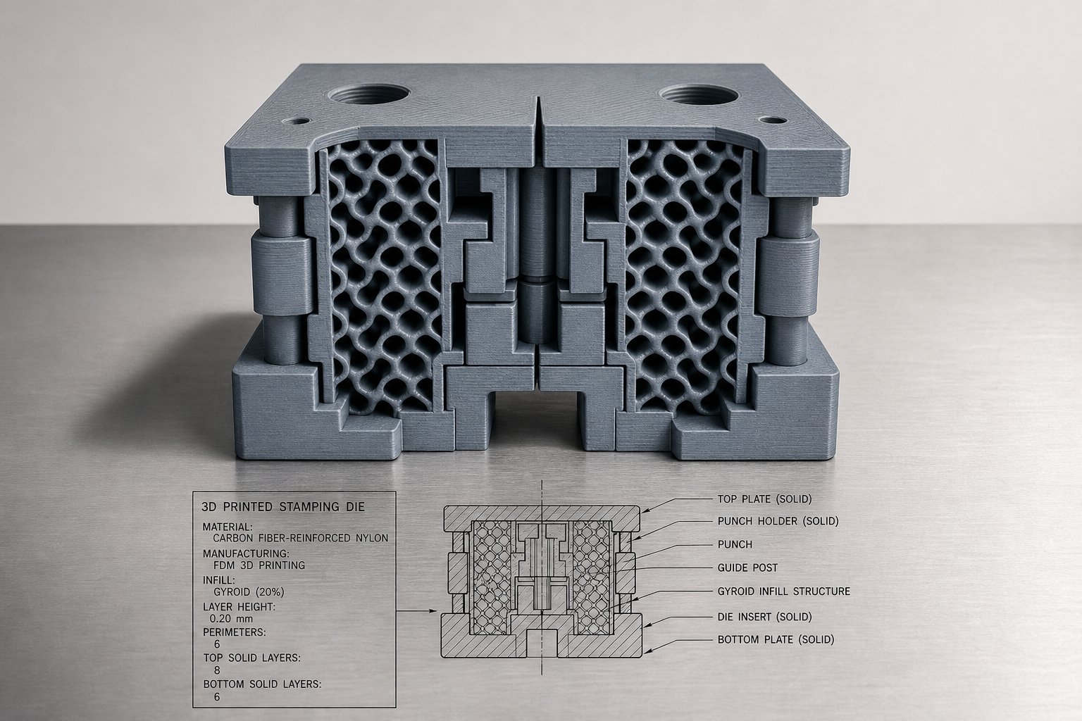
The 3D printed die infill pattern for strength matters more than raw infill percentage. A die at 50% gyroid infill can outperform one at 80% grid infill because the internal geometry distributes force more uniformly across the cross-section.
For stamping dies, consider these infill guidelines:
- Minimum 60-70% infill density for dies handling repeated forming loads. Below this threshold, internal voids allow localized compression and eventual collapse under cyclic stress.
- Gyroid or cubic infill patterns provide near-isotropic internal support. Grid and rectilinear patterns create aligned weak planes that can shear under off-axis loads.
- 100% solid infill in the top 5-8 mm directly below the forming surface. This creates a solid cap that transfers press force uniformly into the infill structure below, preventing surface deflection or punch-through.
- Increase shell/perimeter count to 5-8 walls for the outer boundary. Perimeters carry more load than infill - multiple continuous perimeters distribute cyclic stresses more effectively than a single thick wall, improving fatigue performance under repeated press cycles.
- Use ribs instead of uniformly increasing infill: Internal ribs oriented perpendicular to the primary forming force add stiffness far more efficiently than raising global infill percentage. This saves print time while reinforcing critical load paths.
A practical approach: print dies at 70% gyroid infill with 6 perimeters and 8 solid top layers. This balances print time against structural performance and gives you a reliable starting point for testing.
Punch-to-Die Clearance for Printed Tools
Standard punch and die clearance for metal stamping uses a percentage-per-side formula based on workpiece thickness and material hardness. For conventional steel tooling, the recommended clearance typically starts at 10% of the workpiece thickness per side, with harder materials requiring up to 15-20%.
Punch and die clearance for printed tooling requires adjustment beyond these standard formulas for two reasons:
- Dimensional variance: Printed dies have inherent tolerances of +/- 0.1 to 0.5 mm depending on the printing process. This variance must be added to the nominal clearance calculation. An FDM die with +/- 0.3 mm tolerance effectively shifts the clearance by up to 0.6 mm total across both halves of the tool.
- Material compliance: Polymer dies deflect elastically under forming force. The die surfaces compress slightly during the stroke, temporarily reducing the effective clearance. To compensate, increase nominal clearance by 5-10% beyond what you'd specify for steel tooling. For example, if a steel die pair calls for 0.15 mm clearance per side on 1.0 mm mild steel, a printed die pair might need 0.20-0.25 mm per side to achieve equivalent results.
Test clearance empirically by starting slightly oversize and reducing in 0.05 mm increments across iterations. With printed tooling, producing a revised die takes hours instead of days, so iterating on clearance is fast and inexpensive.
One more consideration: forming geometry complexity should follow a progressive path. Start with simple V-bends where the force is predictable and uniformly distributed. Move to U-bends and channel forms only after validating die survival. Draws and compound forms introduce tensile loads across the die face and multi-directional stress - these require the highest infill densities, thickest walls, and most conservative clearance values. Attempting a deep draw on the first print almost always ends in die fracture.
These design parameters define what the die can structurally survive. But the other half of the equation is what's being formed - the specific metal alloy, temper, and thickness pushing back against the tool determine whether your geometry holds or fails.
Compatible Metals and Thickness Limits
Your die material sets the ceiling on forming force. But the sheet metal pushing back against that die is what actually determines whether the operation succeeds or fails. Not every alloy plays well with polymer tooling, and even cooperative metals become problematic once thickness exceeds certain thresholds. Understanding what metals can you stamp with printed dies - and where the hard limits sit - prevents wasted prints and cracked tools.
Alloys and Tempers Suited to Printed Dies
Soft, ductile metals require less force to form, which directly extends the usable range of printed tooling. The best candidates share a common trait: low yield strength combined with high elongation before fracture.
- Aluminum alloys (1100, 3003, 5052, 6061-O): The ideal starting point for aluminum forming with printed stamping dies. Alloy 5052-O, for example, has a yield strength around 90 MPa and elongation above 25%, making it highly cooperative with polymer dies in thin gauges.
- Brass (C260, C270): Cartridge brass in annealed condition offers excellent formability with yield strength near 100-120 MPa. Slightly harder on dies than aluminum due to higher stiffness, but well within polymer capability for thin stock.
- Copper (C110, C101): Dead soft copper forms with very low force and conforms easily to die geometry. Excellent for printed tooling in all common thicknesses up to the die's compressive limit.
- Mild steel (1008, 1010, 1018): Annealed low-carbon steel with yield strength around 200-250 MPa. Workable with reinforced printed dies in thin gauges, but forces climb quickly with thickness.
- Stainless steel (304, 316): Annealed austenitic grades are formable but require substantially more force than mild steel. Generally the upper limit for polymer dies, restricted to very thin stock with high-strength die materials like carbon-fiber nylon or rigid resin.
Temper condition matters as much as alloy choice. Annealing restores ductility by recrystallizing the grain structure, which reduces yield strength and increases elongation - both properties that lower the forming force your die needs to handle. A half-hard 5052 aluminum sheet requires roughly twice the bending force of the same alloy in fully annealed condition. When working with printed tooling, always specify annealed or dead soft temper unless the application specifically requires a harder condition in the final part.
This relationship is straightforward: softer metal means less die stress, longer die life, and better compatibility with polymer tooling. If your design allows post-forming heat treatment or work hardening, start with annealed stock and add strength afterward rather than fighting a harder temper during the forming step.
Thickness Limits by Die Material
Sheet metal thickness limits for 3D printed dies depend on the interaction between die compressive strength and the forming force generated by a given metal at a given thickness. Thicker stock multiplies required force exponentially - doubling sheet thickness roughly quadruples bending force.
| Die Material | Aluminum (annealed) | Brass (annealed) | Copper (soft) | Mild Steel (annealed) | Stainless Steel (annealed) |
|---|---|---|---|---|---|
| PLA | 0.5 mm | 0.4 mm | 0.5 mm | 0.3 mm | Not recommended |
| ABS | 0.8 mm | 0.6 mm | 0.8 mm | 0.5 mm | Not recommended |
| Nylon (PA) | 1.0 mm | 0.8 mm | 1.0 mm | 0.8 mm | 0.4 mm |
| Polycarbonate | 1.2 mm | 1.0 mm | 1.2 mm | 1.0 mm | 0.5 mm |
| Carbon Fiber Nylon | 1.5 mm | 1.2 mm | 1.5 mm | 1.0 mm | 0.6 mm |
| Rigid/Engineering Resin | 1.0 mm | 0.8 mm | 1.0 mm | 0.8 mm | 0.5 mm |
| Metal Sintered (Maraging Steel) | 3.0+ mm | 2.5+ mm | 3.0+ mm | 2.5+ mm | 2.0+ mm |
These values assume simple V-bends with properly designed clearances and moderate bend lengths. Draws, compound forms, and long bend lines push forces higher, which means reducing the maximum allowable thickness accordingly. A pilot study using 3D printed Maraging steel dies for hot stamping demonstrated successful forming of 1.7 mm coated boron steel over 800 cycles - confirming that metal-sintered dies handle heavier gauges and harder alloys with production-level durability.
Surface Finish Transfer From Die to Part
Here's a detail most tooling guides skip entirely: the surface finish from 3D printed tooling transfers directly onto the formed sheet metal. Every layer line, every stair-step artifact, and every surface imperfection on the die face imprints into the workpiece under press force. On soft metals like annealed aluminum or copper, this effect is especially pronounced because the material conforms closely to the die surface during forming.
The severity depends on print technology:
- FDM dies leave the most visible marking. Layer heights of 0.1-0.3 mm produce ridges that imprint clearly into thin aluminum. The pattern is directional and repeatable - you'll see parallel lines on the formed part wherever it contacted the die face.
- SLA dies produce the cleanest surfaces among polymer options. Layer heights of 0.025-0.05 mm leave minimal visible texture on formed parts, often acceptable without further treatment.
- SLS dies transfer a slightly matte, granular texture from the powder-sintered surface. Less directional than FDM lines, but still visible on reflective metals.
Strategies to minimize surface transfer:
- Sand the forming faces with progressively finer grits (220 through 600) to knock down layer lines before use. This is the simplest and most effective intervention for FDM dies.
- Apply a thin epoxy or filler coat to the die surface and sand smooth. This fills micro-gaps between layers and creates a continuous forming face.
- Orient the print so layer lines run parallel to the direction of material flow during forming. Parallel lines create less visual disruption than perpendicular ridges and reduce the risk of marking.
- Use a sacrificial shim - a thin sheet of smooth polyethylene or PTFE between die and workpiece. This adds compliance but eliminates direct texture transfer on cosmetic parts.
For parts where surface quality matters, plan for post-forming finishing or invest in SLA-printed dies with sanded forming faces. For structural parts hidden from view, the texture from an unfinished FDM die is often acceptable as-is.
Knowing which metals your die can form and how thick you can push them establishes the operational envelope. The next question is more quantitative: exactly how much force does a given forming operation generate, and can your die survive it?
Force Calculations and Press Tonnage Limits
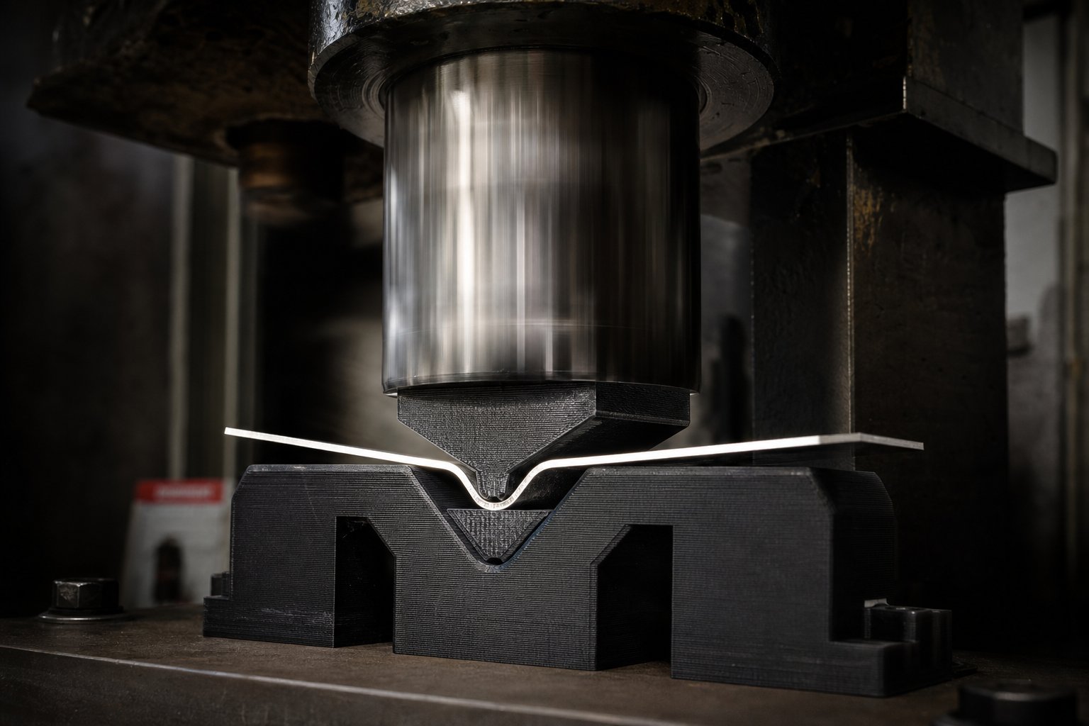
You know which metal you're forming and how thick it is. You've selected a die material with a known compressive strength. The critical step between those two data points is quantifying exactly how much force the forming operation generates - and whether your printed die can absorb it without catastrophic failure. This is the forming force calculation for 3D printed dies that most guides never address.
Estimating Forming Force for Sheet Metal
The standard air-bending tonnage formula, widely used in press brake operations, provides a reliable starting point:
Forming tonnage = {[575 x (Material thickness2)] / Die-opening width / 12} x Length of bend x Material factor
Material thickness, die-opening width, and bend length are all in inches. The constant 575 is calibrated against AISI 1035 cold-rolled steel at 60,000 PSI tensile strength. To adapt this for other metals, you apply a material factor - the ratio of your sheet metal's tensile strength to that 60,000 PSI baseline. Some common factors:
- Dead soft aluminum (H-series): 0.5
- T-6 aluminum: 1.0 - 1.2
- Mild steel (AISI 1035): 1.0
- 304 stainless steel (84,000 PSI tensile): 1.4
- Brass (annealed, ~45,000 PSI tensile): 0.75
Imagine you're bending 1.0 mm (0.040 in.) annealed aluminum over a 6 mm (0.25 in.) die opening with a 100 mm (4 in.) bend length. Plugging those values in: {[575 x (0.0402)] / 0.25 / 12} x 4 x 0.5 = roughly 0.06 tons, or about 540 N of force. That's comfortably within the capability of most nylon or polycarbonate dies.
The relationship is important to internalize: forming force increases with the square of material thickness. Double the sheet thickness and you quadruple the required force. This exponential scaling is why the thickness limits in the previous section exist - printed dies hit their compressive ceiling fast as gauge increases.
Press Tonnage Limits for Printed Tooling
How much force can a printed die handle? The answer lies in comparing the calculated forming force against the die's compressive strength distributed over its contact area.
Here's the conceptual framework: if your die face has a contact area of 500 mm2 and the die material has a compressive yield strength of 100 MPa, the theoretical maximum load before permanent deformation is 50,000 N (roughly 5 metric tons). The press tonnage limit for plastic tooling is simply the die's contact area multiplied by its compressive yield strength, then reduced by a safety margin.
Key variables engineers should account for when determining whether a printed die survives a given operation:
- Sheet metal tensile strength - directly determines forming force via the material factor
- Sheet thickness (squared) - the dominant variable in the force equation
- Bend length - longer bends produce proportionally higher total force
- Die-opening width - narrower openings concentrate force and increase tonnage requirements
- Die contact area - larger contact surfaces distribute force across more material, reducing local stress
- Die material compressive yield strength - the maximum stress the die can sustain without permanent deformation
- Safety factor - the mandatory derating applied to account for material variability and sudden failure modes
The safety margin for additive manufactured stamping dies deserves special emphasis. Steel dies loaded beyond their capacity deform gradually - they mushroom, they yield visibly, they give warning. Printed polymer dies do not. They fracture suddenly and without prior deformation, especially rigid resins and glass-filled materials. This brittle failure mode means you cannot rely on visual inspection to detect an overloaded die approaching its limit.
For polymer dies, apply a minimum safety factor of 3x - meaning your calculated forming force should not exceed one-third of the die's theoretical compressive capacity. For rigid resins, which fail with zero warning, a 4x safety factor is more appropriate. Only tough nylon and polycarbonate, which exhibit some plastic deformation before fracture, can justify working closer to a 2.5x margin.
A practical check: calculate your forming force using the formula above, divide your die's compressive capacity (yield strength x contact area) by that force, and confirm the resulting ratio meets your safety threshold. If it doesn't, you have three options - increase die contact area, switch to a stronger die material, or reduce sheet thickness. Running a printed die near its calculated limit is not a cost-saving measure. It's a path to sudden tool failure, damaged workpieces, and potential press damage.
These force calculations tell you whether a single forming stroke is survivable. But tooling economics depend on more than one stroke - die lifespan, iteration cost, and break-even volume against conventional machined tooling define whether printed dies actually save money across a project's full lifecycle.
Cost-Benefit Framework and Break-Even Analysis
A printed die that costs $40 sounds like a clear win over a $2,000 machined tool. But that comparison ignores what actually drives project cost: how many parts each die produces before failure, how many design iterations you burn through, and at what volume the cheaper tool stops being cheaper. The real 3D printed die cost vs CNC machined tooling comparison requires a Total Cost of Ownership lens - one that accounts for tooling, iteration, and per-part economics across the full development arc.
Cost Per Part Over Die Lifespan
Printed die lifespan number of parts varies dramatically by material and forming severity. A well-designed nylon die performing simple bends in thin aluminum can survive 200 to 500 cycles. A rigid resin die under moderate load might crack after 50 to 150 parts. PLA? Often single digits before visible degradation.
This lifespan directly determines cost per part with 3D printed dies. A $40 nylon die producing 200 good parts costs $0.20 per part in tooling. A $2,000 CNC-machined steel die producing 100,000 parts costs $0.02 per part. At face value, steel wins - but only if you actually need 100,000 parts and the design never changes.
The real cost equation, borrowing the Total Cost of Ownership framework used across manufacturing processes, looks like this:
Total Project Tooling Cost = (Cost per die x Number of iterations) + (Failed prints x Material cost) + Post-processing labor
Every design revision means a new die. With printed tooling, that revision costs $40 and four hours. With machined tooling, it costs $2,000 and two to four weeks. If your project goes through six iterations before finalizing the part geometry - a common scenario in new product development - the printed tooling path costs roughly $240 in dies. The machined path costs $12,000, assuming you even bother re-cutting that many times instead of guessing and hoping.
Break-Even Analysis Against Traditional Tooling
The break even volume for printed stamping dies sits at the crossover point where cumulative per-part tooling cost on a printed die equals the amortized cost of a machined die. Below that volume, printing wins. Above it, machining takes over.
| Factor | 3D Printed Dies | CNC Machined Dies |
|---|---|---|
| Lead time per die | 4 - 24 hours | 1 - 4 weeks |
| Tooling cost (single die) | $5 - $150 | $1,500 - $10,000+ |
| Cost per design iteration | $5 - $150 + hours | $1,500 - $10,000 + weeks |
| Die lifespan (parts before failure) | 50 - 500 typical | 50,000 - 500,000+ |
| Effective cost per part (tooling only) | $0.10 - $3.00 | $0.01 - $0.10 |
| Break-even volume threshold | Favored below 200 - 500 parts | Favored above 500 - 1,000 parts |
The pattern is clear: printed dies dominate the prototyping and validation phase where designs change frequently and production volumes haven't materialized. Industry data confirms this dynamic - 3D printing maintains a relatively flat cost curve that favors low quantities, while processes with high tooling investment only become economical once that NRE is spread across thousands of units.
Iteration count is the hidden multiplier. A project with two design revisions might break even at 300 parts on machined tooling. That same project with eight revisions - not unusual during early-stage product development - might not break even until 2,000 parts because each machined die revision adds thousands in sunk cost. Printed dies absorb design instability for almost nothing.
Where the economic advantage disappears: once your design is frozen, volumes exceed 500 parts, and die life matters more than iteration speed. At that point, the durability gap overwhelms the upfront cost savings, and every re-print adds friction that a single hardened steel die eliminates entirely.
This break-even math assumes your printed die works in isolation. In practice, many teams extend the useful range of printed tooling by combining it with conventional materials - hybrid approaches that push die life and capability beyond what pure polymer can achieve on its own.
Hybrid Approaches and Rapid Validation Strategies
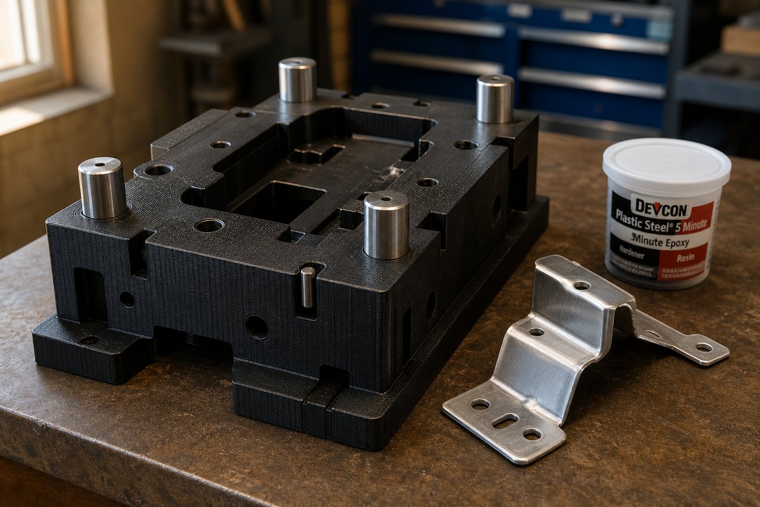
Pure polymer dies have a ceiling. Pure machined steel dies have a price floor. Between those two extremes sits a range of hybrid tooling for sheet metal prototyping that borrows from both worlds - using printed geometry as the foundation while adding conventional materials exactly where they're needed to handle higher loads, extend lifespan, or improve surface quality.
These aren't exotic techniques. They're practical upgrades that teams apply incrementally as forming requirements outgrow what a standalone printed die can deliver.
Reinforcing Printed Dies With Metal Inserts
The most common failure point on a printed die is the forming edge - the small radius where sheet metal bends around the tool. This concentrated contact zone sees peak compressive stress and wears fastest. Reinforcing 3D printed dies with metal inserts at these critical zones dramatically extends tool life without rebuilding the entire die in steel.
The approach is straightforward: design the die body with recessed pockets at high-wear areas, then press-fit or bond hardened steel pins, dowels, or machined inserts into those pockets. The printed body handles bulk geometry and alignment, while the metal insert handles the actual forming contact. A die that might survive 100 cycles as pure nylon can reach 1,000+ cycles with steel-insert edges.
Common insert strategies include:
- Hardened dowel pins at bend radii where sheet metal wraps around the die edge
- Flat ground steel plates bonded to the forming face for uniform load distribution
- Threaded inserts embedded during the print (using pause-and-insert techniques) for mounting and alignment features
Backing Strategies for Extended Die Life
When the die geometry is complex but the structural demand exceeds what solid-infill plastic can sustain, backing the printed shell with a rigid filler transforms a fragile tool into a robust one. Epoxy backed 3D printed die shells are particularly effective - you print a thin-walled die with accurate forming surfaces, then fill the interior cavity with aluminum-filled epoxy or structural urethane.
Research into hybrid rapid tooling with different backing materials found that aluminum backing provided the best balance of cost, dimensional accuracy, and process efficiency - enhancing performance by 68% compared to unbacked tooling while maintaining transcription rates above 93%.
Here's the progression of hybrid reinforcement strategies, ordered from simplest to most advanced:
- Sand and coat forming surfaces - Fill layer lines with thin epoxy, sand smooth. Adds surface durability with zero structural change to the die body.
- Press-fit metal inserts at wear edges - Steel dowels or ground pins at bend radii. Extends edge life 5-10x with minimal design complexity.
- Epoxy-fill the die interior - Print a hollow shell with accurate external geometry, then pour aluminum-filled epoxy inside. The epoxy provides compressive support while the printed shell maintains dimensional accuracy.
- Bond printed die to a machined metal backing plate - Use the printed component as the precision forming surface, bolted or bonded to a steel or aluminum plate that absorbs bulk press force. This separates the geometry problem (handled by printing) from the structural problem (handled by metal).
- Use printed dies as patterns for cast urethane or epoxy tooling - Print accurate master geometry, then cast production-grade urethane or epoxy composite dies from that master. One printed pattern generates multiple cast dies, each lasting hundreds of cycles. This approach makes sense when you need several identical die sets or when the printed material itself can't handle the forming environment.
Each step up adds cost and time, but also multiplies die capability. The key insight is that you don't need to choose between printed and conventional - you combine them at the interface where each technology does its best work.
Validating Parts Before Full Tooling Investment
Hybrid dies solve the tooling durability problem. But there's a broader validation question that printed dies alone can't answer: will the stamped part actually work in its final application? A formed prototype made from a printed die confirms geometry and basic fit, yet it may not capture the material behavior, spring-back characteristics, or surface quality of a production-stamped part.
This is where the development workflow benefits from validating stamped parts before production tooling through a complementary path. Rather than jumping directly from printed-die prototypes to $10,000+ hardened production dies, experienced teams insert a rapid prototyping stage that produces actual metal parts - via CNC machining or professional sheet metal fabrication - to confirm manufacturability and functional performance.
The logic is sound: your printed die proved the geometry works. A CNC-prototyped or fabricated metal sample proves the part performs under real conditions, with production-representative material properties and surface finish. This two-stage validation catches DFM issues (draft angles, minimum radii, spring-back allowances) before you commit capital to production tooling.
Teams using services like YICHEN's rapid prototyping approach this gap by combining CNC machining and sheet metal fabrication to produce functional metal samples with early DFM feedback. The result is a validated part design - confirmed both geometrically (via printed dies) and functionally (via prototyped metal parts) - before any production die is ever cut. That two-step validation typically saves far more in avoided tooling revisions than it costs in prototyping services.
Hybrid strategies extend what printed dies can physically accomplish. But every approach still has a boundary - a point where material fatigue, force requirements, or volume demands push beyond what any combination of printed and reinforced tooling can sustain reliably.
Limitations and When to Move Beyond Printed Dies
Every tooling method has a failure envelope. Printed dies are no exception, and pretending otherwise would undermine everything this guide has established. The 3D printed die failure modes and limits are real, predictable, and - if ignored - expensive. Knowing exactly where these tools break down lets you use them confidently within their capability window and transition to harder tooling at the right moment instead of too late.
When Printed Dies Fail
Failure doesn't always look like a dramatic crack mid-stroke. More often, it's gradual degradation that produces increasingly inaccurate parts until the die becomes unusable. Here are the specific scenarios where printed tooling reaches its limit:
- Tonnage ceiling exceeded: Polymer dies cannot survive forces beyond their compressive yield strength multiplied by contact area, even once. A single overload event causes immediate brittle fracture in rigid resins or permanent crushing in thermoplastics. There is no recovery - the die is scrap.
- Printed die fatigue and creep under load: Even at forces well below the single-stroke limit, repeated cycling causes cumulative damage. Creep deformation in 3D printed polymers occurs when molecular chains slip past each other under sustained or repeated stress, resulting in permanent dimensional change over time. FDM plastics are particularly susceptible because their lower melting temperatures mean environmental heat accelerates this molecular movement. A die that measures perfectly on cycle one may be 0.1-0.3 mm oversized by cycle 200.
- Temperature sensitivity: Workshop temperatures above 30-35 degrees C noticeably soften PLA and standard resins. Friction-generated heat during rapid cycling compounds the problem. A die that works fine in a climate-controlled lab may fail in a summer garage or factory floor without air conditioning.
- Geometric complexity limits: Deep draws, compound curves with tight radii, and progressive die operations introduce multi-directional stress states that printed materials handle poorly. Tensile loads across layer bonds in FDM dies, or stress concentrations at thin features in resin dies, create unpredictable failure points that no amount of infill compensates for.
- Surface degradation: Forming contact gradually abrades and polishes the die surface, changing clearance dimensions and surface texture transfer. Soft materials like nylon wear faster than rigid resins but fail more gracefully - the tradeoff is slower degradation versus sudden cracking.
- Dimensional drift without warning: Unlike steel dies that deform visibly before failure, polymer dies can creep dimensionally while still appearing intact. You won't see the problem until formed parts start failing inspection. Creep in polymers occurs even at room temperature due to their viscoelastic nature, where sustained loading causes chains to stretch and rearrange permanently.
The volume threshold for 3D printed stamping tooling typically sits between 200 and 500 parts for well-designed thermoplastic dies, and 50 to 150 parts for resin dies under moderate load. These aren't hard boundaries - they shift with material choice, forming severity, and environmental conditions. But they represent the zone where cumulative wear, creep, and dimensional drift make each subsequent part less reliable than the last.
Volume Thresholds and the Transition to Production Tooling
Knowing when to switch from printed to machined dies isn't a single decision point. It's a progression that follows the natural arc of product development:
- Printed dies for geometry validation (1-50 parts): Confirm that the bend angles, form depths, and overall shape work as designed. Accept surface imperfections and dimensional variance as the price of speed.
- Rapid-prototyped metal parts for functional testing (5-20 parts): Once geometry is validated through printed-die forming, produce actual metal parts via CNC machining or professional fabrication to confirm material behavior, spring-back, and performance under real service conditions. Services like YICHEN's rapid prototyping bridge this gap by providing CNC-prototyped and fabricated metal parts that confirm manufacturability - catching DFM issues before you invest in hardened tooling.
- Production tooling for volume (500+ parts): With geometry validated and manufacturability confirmed, invest in CNC-machined steel dies with confidence that no expensive revision cycle awaits.
This staged approach minimizes total project risk. Printed dies absorb the design instability of early development. Rapid-prototyped metal parts confirm that the final design is actually producible at scale. Production dies only get cut once, for a frozen design.
Before committing to any approach, run through this evaluation checklist for your specific application:
- Is your forming force below one-third of the die material's compressive capacity? If not, printed tooling is undersized.
- Do you need more than 500 identical parts? If so, the economics favor machined dies regardless of printed die capability.
- Does the formed part require surface finish quality below Ra 1.6? Printed dies without extensive finishing won't deliver this.
- Will the die operate in temperatures above 35 degrees C? Factor in material softening and accelerated creep.
- Does the geometry involve deep draws or compound forms with tensile stress across the die face? These push printed materials into unpredictable failure territory.
- Can you tolerate +/- 0.2 to 0.5 mm dimensional variation across a production run? If tighter consistency is required, steel tooling is the answer.
3D printed stamping dies aren't a replacement for conventional tooling. They're a development-phase accelerator that collapses weeks of lead time and thousands of dollars into hours and pocket change - within a defined capability envelope. Use them where they excel, transition when they don't, and you'll reach production tooling faster, cheaper, and with fewer surprises than teams who skip the validation steps entirely.
Frequently Asked Questions About 3D Printed Stamping Dies
1. How many parts can a 3D printed stamping die produce before it fails?
Die lifespan depends heavily on the printing material and forming severity. Well-designed nylon or polycarbonate dies performing simple bends in thin aluminum typically survive 200 to 500 cycles. Rigid resin dies under moderate load last around 50 to 150 parts. PLA dies often degrade within single-digit uses. Hybrid approaches, such as adding steel inserts at bend radii or epoxy-filling the die interior, can extend lifespan to 1,000+ cycles by reinforcing high-wear contact zones while keeping the printed body for bulk geometry.
2. What metals can you stamp with 3D printed dies?
Soft, ductile metals in annealed temper work best with polymer dies. Annealed aluminum alloys (1100, 3003, 5052, 6061-O) are ideal candidates, followed by annealed brass, dead soft copper, and thin-gauge mild steel. Stainless steel is generally the upper limit, restricted to very thin stock (under 0.6 mm) with high-strength die materials like carbon-fiber nylon. Always specify annealed or dead soft temper when ordering sheet metal for printed-die forming, since harder tempers can double the required bending force.
3. Are 3D printed stamping dies cheaper than CNC machined tooling?
For prototyping and volumes under 500 parts, printed dies cost dramatically less. A single nylon die runs $15 to $50 versus $1,500 to $10,000 for CNC-machined steel. The cost advantage grows with each design iteration, since reprinting a revised die costs pocket change compared to re-machining. However, the economics reverse above 500 to 1,000 parts because machined steel dies last 50,000 to 500,000+ cycles, driving per-part tooling cost below $0.10. Teams like YICHEN's rapid prototyping service help bridge this gap by validating part manufacturability through CNC-prototyped metal samples before committing to expensive production dies.
4. What is the best 3D printing material for stamping dies?
Carbon-fiber-reinforced nylon offers the strongest overall performance for most stamping die applications. It combines compressive strength around 100 to 130 MPa with excellent dimensional stability, low thermal expansion, and resistance to creep under repeated loads. For budget prototyping, standard nylon (PA6 or PA12) provides a good balance of toughness and cost. Rigid engineering resins from SLA printers deliver superior surface finish and isotropy but fail suddenly without warning under overload. Material choice should match your specific forming force, cycle count, and surface quality requirements.
5. How do you calculate if a 3D printed die can handle a specific forming operation?
Calculate the required forming force using the air-bending tonnage formula, which factors in sheet thickness squared, bend length, die-opening width, and a material multiplier based on alloy tensile strength. Then compare that force against your die's compressive capacity (yield strength multiplied by contact area). Apply a minimum safety factor of 3x for thermoplastics and 4x for rigid resins, because polymer dies fracture suddenly without warning unlike steel dies that deform gradually. If the safety ratio falls below threshold, increase die contact area, switch to a stronger material, or reduce sheet thickness.


