
Line Die Stampings Decoded: From Die Setup to Production-Ready Parts
What Are Line Die Stampings and Why Terminology Matters
Imagine you're sourcing a deep-drawn automotive bracket, and one supplier quotes you on a "line die," another on a "transfer die," and a third simply calls it a "line/transfer die setup." Are they describing the same process? The answer is nuanced - and getting the terminology right can save you from costly miscommunication during tooling development.
Defining Line Die Stampings in Metal Forming
Line die stampings are parts produced through a multi-station metal forming process where individual, single-operation dies are arranged in a sequential line - each mounted on its own press station or spaced along a shared press bed. A flat metal blank enters the first station, undergoes one specific operation such as blanking, drawing, or trimming, and is then physically transferred to the next station for the following operation. This station-by-station approach continues until the finished part emerges at the end of the line.
Line die stamping is a sequential metal forming process that uses a series of individual, standalone dies - each performing a single operation - with workpieces physically transferred between separate press stations to produce finished parts in multiple controlled steps.
What makes this method distinct is the use of discrete die sets. Each station operates as its own self-contained tool, giving engineers the freedom to design, modify, or replace individual stations without overhauling the entire tooling package. This modularity is one of the reasons line die configurations are favored for larger parts, deep-drawn geometries, and components that demand forming operations from multiple angles.
How Line Dies Differ from Progressive and Transfer Dies
The differences between die stamping methods come down to how material enters the process and how parts move between operations. In progressive die metal stamping, a continuous metal strip feeds from a coil directly into a single die set containing multiple stations. The strip advances incrementally, and each press stroke performs a different operation at each station simultaneously. The part remains attached to the carrier strip throughout, only separating at the final station. Progressive die and stamping systems excel at producing small-to-medium parts at very high volumes with minimal handling.
Transfer die stamping, by contrast, works with pre-cut blanks rather than continuous strip stock. A blank is cut and then moved between stations using mechanical transfer systems - such as servo-driven arms, walking beams, or crossbar mechanisms - that grip, lift, and reposition the workpiece at each stage. As Dundee Manufacturing explains, transfer systems can be mechanical, pneumatic, hydraulic, or servo-driven, depending on part complexity and size. The workpiece is independent from any carrier strip, which allows for larger part sizes and more complex three-dimensional forming.
Line dies occupy the broadest position in this family. They refer to any arrangement of standalone stamping dies in a sequential configuration - whether parts are moved by hand, by gravity slide, or by robotic automation. Transfer die stamping is effectively a subset of line die stamping where automated mechanical systems handle the part movement between stations.
Clearing Up Industry Terminology Confusion
Here's where things get confusing in practice. Many manufacturers and even industry publications use "line die" and "transfer die" interchangeably. You'll find suppliers describing identical setups under different names, and competitive quotes that blur the lines between these terms. This inconsistency isn't just semantic - it affects how engineers communicate tolerances, cycle times, and tooling requirements.
A clearer taxonomy looks like this:
Term | Definition | Part Transfer Method |
|---|---|---|
Line Die Stamping | Broad category: individual dies in sequence across separate stations | Manual, semi-automated, or fully automated |
Transfer Die Stamping | Specific subset: automated mechanical systems move parts between stations, often within a single press bed | Mechanical fingers, servo arms, walking beams |
Progressive Die Stamping | Continuous strip fed through multiple stations in one die set | Strip carrier - part stays attached until final cutoff |
When someone mentions "progressive die and stamping" processes in conversation, they're almost always referring to the coil-fed, single-die-set method. Line dies, on the other hand, always involve discrete die sets and separated blanks - a fundamental difference that shapes everything from press layout to cycle time expectations.
With this taxonomy in place, the real question becomes practical: how does a blank actually move through a line die setup, and what happens at each station along the way?
How the Line Die Stamping Process Works Step by Step
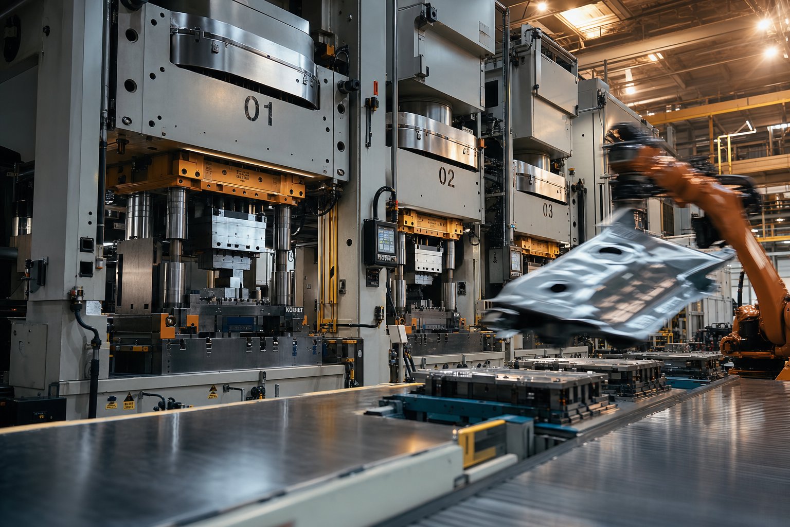
Picture a shop floor with four, five, or even eight individual presses arranged in a row - each one loaded with its own dedicated stamping die, each performing just one forming or cutting operation. A flat metal blank enters at one end, and a fully shaped part exits at the other. That, in its simplest form, is a line die stamping operation. But the details between entry and exit are what separate a smooth-running production line from one plagued by scrap and downtime.
Blank Preparation and Initial Loading
Every line die process starts with a blank - a flat piece of sheet metal cut to a precise size and shape before it ever touches a stamping die. This is a critical distinction from progressive stamping, where coil stock feeds directly into the die set from a decoiler. In a line die setup, blanks are typically sheared or laser-cut from sheet or coil stock at a separate blanking station, then stacked on pallets for transport to the press line.
Why does this matter? Because blank dimensions directly influence material flow during drawing and forming operations downstream. An oversized blank wastes material and can cause wrinkling; an undersized one risks tearing. Engineers calculate blank size based on the finished part's surface area, draw depth, and trim allowances - essentially reverse-engineering the flat pattern from the final 3D geometry.
Once stacked and staged, blanks are loaded onto a destacker at the head of the press line. As Metal Forming Magazine notes, a double-blank detection system is essential at this stage to prevent two blanks from feeding simultaneously - a scenario that can overload the press or damage tooling. After destacking, blanks may pass through a washer/oiler station that applies lubrication to reduce friction during forming.
Station Sequencing and Operation Types
Each station in the line holds a standalone die set - its own stamp and die combination - engineered for a single operation. The part's geometry dictates both the order of operations and the total number of stations required. A relatively simple bracket might need only four stations, while a deep-drawn automotive panel could require seven or eight.
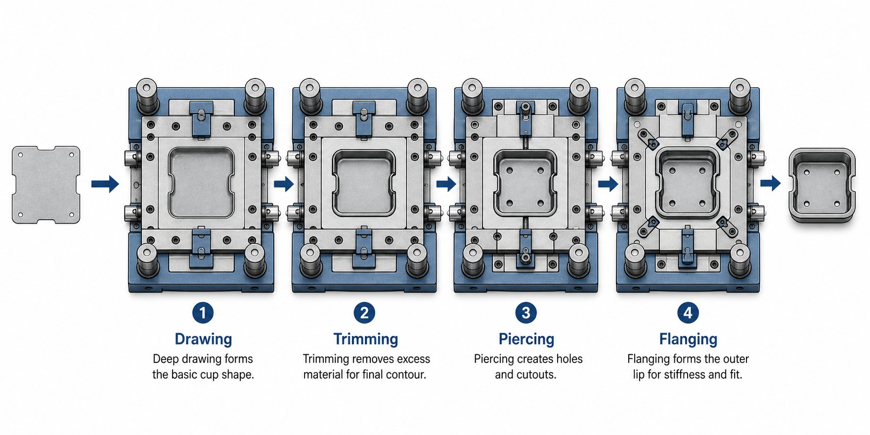
Here's what a typical process die sequence looks like for a moderately complex drawn part:
- Blank loading and centering: The flat blank is positioned on locating pins or nests in the first station to ensure precise orientation.
- Initial draw: The blank is drawn into a rough 3D shape using a draw die with a blank holder that controls material flow and prevents wrinkling.
- Redraw or restrike: For parts with significant depth, a second draw or restrike operation refines the shape, tightens radii, and improves dimensional accuracy.
- Trim: Excess flange material and draw allowance are cut away, bringing the part closer to its final profile.
- Pierce: Holes, slots, and other internal features are punched into the formed part using piercing punches matched to hardened die buttons.
- Flange and cam form: Edges are bent to final angle specifications, and any features requiring off-axis forming are shaped using cam-driven die sections.
- Final trim and quality check: Remaining scrap is removed, and the finished part is ejected for inspection or sent directly to packaging.
Not every part requires all seven steps. Engineers add or remove stations based on draw depth, the number of pierced features, and whether off-angle forming is needed. The flexibility to tailor each station independently is one of the core advantages of this approach - if a design change adds a hole pattern, you modify or add one die stamp station rather than re-engineering an entire progressive die set.
Press Line Layout and Part Flow
The physical arrangement of presses on the shop floor is more than just logistics - it directly affects cycle time, part quality, and operator safety. In a tandem press line, which is the most common configuration for line die stampings, each station sits in its own dedicated press. Industry data indicates that tandem lines typically feature four to six presses: a lead press (also called the head press) handles the initial draw operation, while follower presses perform trimming, piercing, flanging, and restrike work. The lead press usually carries the highest tonnage rating and may include hydraulic cushions to support blank holding during deep draws.
Press spacing must account for the transfer mechanism - whether that's a robot arm, a shuttle system, or an operator physically moving parts. Enough clearance is needed for the part to be lifted clear of the lower die, rotated or reoriented if necessary, and placed accurately into the next station's locating nest. Part orientation between stations is critical; a blank that enters a draw die with a 5-degree rotational error will produce a part with misaligned trim lines and off-location holes.
Scrap handling is another layout consideration that's easy to overlook. Each trimming and piercing station generates offal - the slugs and skeleton material left over after cutting. Chutes positioned beneath each die direct scrap into bins or conveyors running below floor level, keeping the working area clear and preventing loose scrap from interfering with part transfer. In high-volume automotive lines, scrap conveyors run continuously to dedicated baling stations.
Typical hit rates for tandem press lines range from around 6 strokes per minute with conventional mechanical presses to more than 18 strokes per minute using servomechanical presses in continuous mode - a threefold difference that underscores how press technology and line layout choices ripple through production economics.
Of course, understanding the process flow is only half the equation. The real performance differences between line die setups, progressive dies, and transfer systems become clear when you compare them side by side against the factors that actually drive tooling decisions.
Line Die vs Progressive Die vs Transfer Die Stamping
You know the process steps, you understand how blanks move through a line die setup - but how do you decide whether a line die configuration is actually the right call for your project? The answer depends on a handful of measurable factors: part size, production volume, material thickness, geometric complexity, and budget. Comparing these three stamping methods side by side reveals where each one earns its place on the shop floor.
Progressive Die Stamping Strengths and Limits
So what is a progressive die, exactly, in practical terms? It's a single die set containing multiple stations through which a continuous metal strip advances with each press stroke. Every station performs a different operation - blanking, piercing, bending, forming - and the part stays connected to the carrier strip until the final cutoff. This strip-fed design is what gives progressive stamping its speed advantage: cycle rates can reach 30 to 60+ strokes per minute, far outpacing line die setups.
That speed comes with constraints. Progressive dies work best for small-to-medium parts - think brackets, clips, connectors, and structural reinforcements - because the part must remain attached to the strip throughout the forming sequence. Large parts, deep draws, and geometries that require substantial three-dimensional forming simply can't be produced while tethered to a flat carrier strip. Material utilization also tends to be lower, since the strip requires spacing between stations and carrier webbing that becomes scrap.
Progressive stamping dies also demand higher upfront tooling investment for a single die set. A complex progressive die with 15 or 20 stations represents a significant engineering and machining effort. Modifying one station can affect the strip layout for every other station downstream, making design changes more involved than in a line die setup where each station is independent.
Where Line Die Stamping Outperforms Alternatives
Line die stampings earn their place when parts are too large, too deep, or too geometrically complex to feed as strip stock through a progressive die. Imagine forming an automotive hood inner panel or an appliance housing enclosure - these parts require deep draws, multi-angle flanging, and extensive trimming that would be physically impossible in a strip-fed configuration.
Because each die station is a standalone unit, engineers gain flexibility that progressive dies simply can't offer. Need to add a restrike operation because a new material grade springs back more than expected? Insert a station. Want to adjust a trim profile without affecting the draw die upstream? Swap out one tool. This modularity makes line dies especially practical for programs that may see mid-cycle engineering changes or where multiple variants of a part share some - but not all - forming operations.
Transfer die stamping, the automated subset of line die work, bridges the gap between the two extremes. Using mechanical transfer bars, servo arms, or robotic systems within a single large press, transfer setups move pre-cut blanks through multiple stations automatically. They're ideal for mid-to-large parts at moderate-to-high volumes - think structural automotive components like crossmembers, reinforcement brackets, and door inners. Transfer die stamping offers faster cycle times than a manual tandem line die arrangement while retaining the ability to handle parts that exceed progressive die size limits.
Decision Matrix for Choosing the Right Approach
The following comparison table lays out the key decision factors across all three methods. Rather than fabricated numbers, you'll find qualitative ratings that reflect real-world trade-offs - the kind of information that helps you narrow your options before engaging a tooling supplier.
Decision Factor | Progressive Die Stamping | Line Die Stamping (Tandem) | Transfer Die Stamping |
|---|---|---|---|
Part Size Range | Small to medium | Medium to very large | Medium to large |
Annual Production Volume | High to very high | Low to high | Medium to high |
Material Thickness Range | Thin to medium gauge | Thin to heavy gauge | Thin to heavy gauge |
Geometric Complexity | Moderate (2D-dominant features) | High (deep draws, multi-angle forms) | High (deep draws, complex 3D shapes) |
Tooling Cost | High (single complex die set) | Moderate per station, but cumulative | High (die sets plus transfer mechanism) |
Cycle Time | Fast (30-60+ SPM) | Slow to moderate (6-15 SPM) | Moderate (15-25 SPM) |
Scrap Rate | Medium to high (carrier strip waste) | Low to medium | Low to medium |
Material Utilization | Low to moderate | High | High |
Changeover Flexibility | Low (die changes affect full strip layout) | High (individual stations are independent) | Moderate (stations independent, but transfer tooling must match) |
Best Suited For | High-volume small parts: clips, brackets, connectors | Large panels, deep-drawn housings, structural parts | Mid-to-large structural components, body panels |
A few patterns stand out. Progressive dies dominate when speed and volume are the top priorities and the part fits within strip-feeding constraints. Line die setups take over when part size or draw depth exceeds those limits - you simply can't form a 600 mm deep enclosure while it's still attached to a coil strip. Transfer die stamping occupies the middle ground, combining the blank-handling flexibility of line dies with automated part movement that boosts throughput.
Choose line die stampings when part size, draw depth, or geometric complexity exceeds progressive die capabilities but production volumes justify investing in dedicated single-station tooling across multiple press stations.
Cost is never a single-line comparison. A progressive die set might cost more than any individual line die, but a complete tandem line setup - four to eight separate die sets, plus press infrastructure, automation, and scrap handling - can equal or exceed a progressive die investment. The difference is how that cost distributes: line die tooling spreads risk across independent stations, while a progressive die concentrates it into one highly engineered package.
The right choice also depends on your material. Thicker gauges and higher-strength steels push decisions toward line die and transfer die configurations, where each station's press tonnage can be individually matched to the operation. Progressive dies, by contrast, require a single press to supply enough force for the most demanding station in the strip - which can mean oversizing the press for most of the operations it performs.
These trade-offs set the stage for an equally important question: what's actually inside each line die station, and how do its components work together to deliver repeatable, production-quality parts?
Essential Components of a Line Die Setup
Every metal stamping die station is essentially a precision sandwich - an upper assembly descending into a lower assembly, with a sheet metal blank caught in between. But here's what makes a line die station different from a station inside a progressive tool: each one is a completely self-contained die set. That independence gives engineers flexibility, yet it also introduces unique challenges around alignment, repeatability, and material selection that deserve a closer look.
Upper and Lower Die Assembly Anatomy
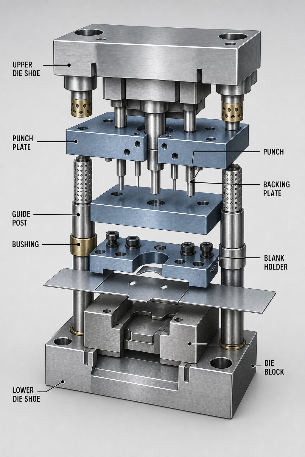
Think of a line die station as two halves working in concert. The upper die assembly - mounted to the press ram - carries the punch that performs the actual forming or cutting work. The lower die assembly sits on the press bolster and contains the die block, which provides the cavity or cutting edge that the punch engages. Between these two halves, guide posts and bushings keep everything precisely aligned through every press stroke.
Here are the essential stamping die components and their functions within a typical line die station:
- Upper die shoe: The top plate that serves as the mounting foundation for all upper die components. It attaches directly to the press ram.
- Punch: The working tool element that contacts the blank and performs the forming, piercing, or cutting operation.
- Punch plate: Holds and locates the punch precisely in position on the upper die shoe.
- Backing plate: A hardened plate between the punch retainer and the upper die shoe that distributes force and prevents the punch from sinking into the softer shoe material under high loads.
- Lower die shoe: The bottom foundation plate that supports the die block, guide posts, and all lower-half components. It typically includes machined openings for scrap and slug removal.
- Die block: Contains the cavity, cutting edges, or forming surfaces that work in conjunction with the punch. In line die draw stations, the die block defines the outer geometry of the formed part.
- Guide posts and bushings: Precision-ground posts - mounted in one shoe and engaging bushings in the opposite shoe - that align the upper and lower halves. As The Fabricator notes, these are manufactured to tolerances within 0.0001 inch and are available in friction-bearing or ball-bearing configurations.
- Blank holder (binder): A pressure-loaded plate in draw stations that clamps the blank's perimeter during forming, controlling material flow and preventing wrinkling.
- Stripper: Removes the workpiece or scrap from around the punch after each stroke, preventing material from lifting with the upper assembly.
- Heel blocks and wear plates: Absorb lateral thrust generated during forming, especially important in stations that produce unbalanced or one-directional forces.
The die shoe is the unsung hero of this assembly. It functions as the structural foundation that maintains parallelism and alignment under repeated loading. Both upper and lower die shoes are machined flat and parallel to tight tolerances - typically through precision milling or grinding. Aluminum die shoes, which weigh roughly one-third as much as steel, are popular for stations where shock absorption matters, such as blanking operations. Steel shoes remain the standard for high-tonnage draw stations that demand maximum rigidity.
In draw operations, a cushion system beneath the lower die shoe provides controlled upward force to the blank holder. Hydraulic or nitrogen gas spring cushions allow engineers to fine-tune blank holder pressure - too little force and the blank wrinkles, too much and the material tears. This adjustability is especially valuable in line die configurations where each station's cushion can be independently calibrated to match its specific forming demands.
Die Materials and Surface Treatments for Line Dies
Choosing the right material for your metal stamping die components is a balancing act between hardness, toughness, and wear resistance. The workpiece material being stamped drives much of this decision.
For punches and die inserts that see high contact pressures, conventional tool steels like D2 (a high-wear, low-shock grade) remain common choices for stamping mild steel and HSLA grades. D2 offers good abrasive wear resistance at hardness values around RC 58-60, making it a workhorse for trimming and piercing stations. However, AHSS Insights research shows that D2 tools forming advanced high-strength steels can fail after just 5,000-7,000 load cycles - roughly one-tenth the tool life expected with conventional steels. The culprit? Insufficient impact strength under the higher working loads these grades demand.
Powder metallurgy (PM) tool steels address this gap. The PM manufacturing process - atomizing molten metal into fine powder, then consolidating through hot isostatic pressing - produces a more uniform microstructure with smaller, evenly distributed carbides. The result is a tool steel that achieves the same RC 58-60 hardness as D2 but with nearly 10 times the impact resistance. For line die stations forming DP steels, martensitic grades, or any material approaching 980 MPa tensile strength, PM tool steels have become the go-to substrate.
Carbide inserts take wear resistance a step further. In stations where localized contact pressure is extreme - sharp draw radii, trim edges, or pierce openings - tungsten carbide inserts provide hardness values far exceeding tool steel. They're expensive, so stamping die design typically reserves carbide for high-wear areas while the surrounding structure uses more economical tool steel grades.
Surface treatments and coatings extend the useful life of any substrate. Common approaches include:
- Ion nitriding: Diffuses nitrogen into the tool surface, creating a hard wear-resistant layer. Effective for galvanized steels where PVD coatings may cause zinc buildup.
- Titanium nitride (TiN) coating: Applied through physical vapor deposition (PVD), this coating reduces friction and resists adhesive wear. PVD processing occurs at lower temperatures than CVD, minimizing the risk of dimensional distortion.
- Titanium aluminum nitride (TiAlN): A PVD coating with excellent performance on uncoated advanced high-strength steels. Research cited by AHSS Insights demonstrates that TiAlN-coated cutting steels produce cleaner, more uniform edges even after 200,000 parts of CR 500Y/800T-DP.
- Chromium nitride (CrN): A PVD-applied coating offering strong galling resistance, particularly useful for stainless steel and aluminum forming operations.
The recommended practice is to complete initial die tryout before applying coatings. Adjustments during tryout - shimming, recutting, or compensating for springback - would otherwise destroy a freshly applied coating. Once the die proves out dimensionally, the final surface treatment locks in performance for production runs.
Alignment and Repeatability Across Stations
Here's the engineering challenge that separates line die stamping from progressive die work: in a progressive die, every station shares the same die shoe, the same guide posts, and the same press ram. Alignment between stations is built into the tool by design. In a line die setup, each station is an independent die set - potentially sitting in a different press, bolted to a different bolster, running under a different ram. Maintaining dimensional consistency from the first station to the last requires careful attention at multiple levels.
Guide post engagement is the first line of defense. MetalForming Magazine emphasizes that the guide bushing should engage the guide post at the working level of the die whenever possible. This loads the post in shear - its strongest condition - rather than bending, which would cause deflection and misalignment between upper and lower halves. Placing bushings higher than the work zone out of convenience is a common design shortcut that compromises precision.
Ball-bearing guide systems offer tighter alignment than plain-bearing friction posts, with preloads ranging from 0.0001 to 0.0021 inch depending on manufacturer and diameter. However, stations generating heavy side thrust - such as cam-forming operations or asymmetric draws - can cause ball tracking, where physical grooves form in the post or bushing surface. For these stations, combining guide posts with boxed-heel construction absorbs lateral forces while the posts maintain vertical alignment.
Between stations, the challenge shifts from internal die alignment to inter-station part positioning. Every time a blank is lifted from one die and placed into the next, there's an opportunity for positional error. Locating nests, pilot pins, and part-specific fixtures in each lower die shoe ensure the workpiece sits in exactly the right position before the ram descends. Even a fraction of a millimeter of rotational or translational error at station two compounds through every downstream operation, resulting in misaligned trim lines, off-location holes, or uneven flanges at the final station.
This compounding-error risk is why line die stamping design places such heavy emphasis on robust part locating features and tight die shoe tolerances at every station. The components inside each die may follow standard conventions, but the real craft lies in making six or eight independent die sets behave as though they're one unified system.
Of course, even perfectly aligned tooling can't compensate for a material that behaves unexpectedly during forming. The metal itself - its grade, thickness, and mechanical properties - shapes every aspect of die design, from blank holder pressure to station count.
Material Selection Guide for Line Die Stamping
A perfectly engineered sheet metal stamping die means nothing if the material running through it fights the process at every station. Each metal alloy brings its own personality to the press line - its own quirks during drawing, its own tendency to spring back, crack, or gall against tooling surfaces. Choosing the right material for a line die operation isn't just a procurement decision; it's a die design decision that ripples through every station from first draw to final trim.
Common Materials for Line Die Stamped Parts
Five material families dominate line die stamping applications, each suited to different performance requirements and forming challenges. Here's how they behave when a press ram pushes them through deep draws, restrikes, and trim operations.
Mild steel (low carbon steel) remains the most forgiving material for multi-station line die work. Its high ductility and relatively low yield strength allow it to flow smoothly over draw radii without cracking, even in deep-drawn geometries. As Sinoway Industry notes, low carbon steel's excellent formability, cost-effectiveness, and consistent surface finish make it a go-to choice for automotive panels, appliance housings, and kitchenware. For die engineers, mild steel means lower blank holder forces, fewer restrike stations, and longer intervals between die maintenance - the easiest material to live with on a production floor.
Advanced high-strength steel (AHSS) is where things get interesting - and challenging. Grades like dual-phase (DP) 590, DP 780, and DP 980 deliver strength-to-weight ratios that automotive OEMs demand for crash performance, but they punish tooling in return. MetalForming Magazine highlights that AHSS creates significantly higher press-pad forces, greater springback, and accelerated die wear compared to conventional steels. Overcrowning - deforming the material in the opposite direction to compensate for springback - can actually work-harden AHSS further, making achieving a specified bend radius impossible without careful simulation. Steel stamping dies running AHSS need upgraded substrates, often powder metallurgy tool steels, along with higher-tonnage presses at each station.
Aluminum alloys - particularly 1100, 3003, and 5052 series - offer lightweight formability but introduce a different headache: galling. Aluminum has a natural tendency to transfer material to die surfaces, building up adhesive deposits that score subsequent parts. Every stamping die steel surface contacting aluminum needs anti-galling coatings such as TiN or CrN, and lubrication management becomes far more critical than with ferrous materials. Aluminum also demands tighter control of blank holder pressure - too much force and the soft material tears, too little and it wrinkles.
Stainless steel combines corrosion resistance with a stubborn tendency to work-harden during forming. Grades 304 and 316 are commonly drawn in line die setups for food containers, medical enclosures, and architectural components. The work-hardening behavior means each successive forming operation encounters a progressively harder material - a challenge that often requires intermediate annealing between stations or the addition of extra restrike stages. Press tonnage requirements run significantly higher than mild steel, and galling risk approaches what you'd see with aluminum. While stainless steel progressive stamping handles thinner gauges and simpler geometries effectively, deep-drawn stainless parts almost always migrate to line die configurations where each station's tonnage and blank holder force can be independently optimized.
Copper and brass alloys offer excellent malleability and electrical conductivity, making them natural fits for deep-drawn electrical housings, plumbing fittings, and decorative components. Formability is high, but the softness that makes copper easy to draw also creates handling challenges - parts dent easily during transfer between stations, and thin-walled copper stampings can deform under their own weight if not properly supported. Progressive stamping materials in the copper family work well for small connectors and terminals, but larger copper enclosures requiring deep draws benefit from the controlled, station-by-station approach of line die setups.
How Material Properties Shape Die Design
You might think material selection and die design are separate decisions. They're not - they're a single conversation. The metal's yield strength, tensile strength, elongation percentage, and work-hardening rate dictate blank holder pressure, draw clearances, punch nose radii, and even how many stations the line requires.
Consider draw clearance as one example. The gap between the punch and the die block in a draw station is typically set at one material thickness plus an additional percentage - roughly 7-10% for mild steel, but potentially 15-20% for AHSS grades that resist thinning differently. Get this wrong and you'll either wrinkle the part wall (clearance too large) or thin it dangerously (clearance too tight).
Material properties also determine whether simulation is a luxury or a necessity. With mild steel, experienced die designers can often predict material flow using empirical rules and past experience. AHSS, however, demands CAE forming simulation before any steel is cut. As the Die Cad Group team explains, simply using blank-unfold software to calculate minimum blank dimensions proves insufficient for advanced steels - you need to model enough stretch in the material, at the right time, to set its shape. Features like lock-bead construction add extra tension during forming but increase blank size and scrap, a trade-off that must be planned from the start rather than discovered during tryout.
Thickness and Grade Effects on Process Parameters
Material thickness amplifies every design consideration. Thicker blanks demand larger die clearances, heavier die shoe construction to resist deflection, and higher-tonnage presses at each station. A 3.0 mm AHSS blank, for instance, can generate enough forming force to deflect a binder plate by several millimeters - enough to completely alter part geometry. MetalForming Magazine documents a case where die-pad deflection on very thick AHSS stock deformed a 6-inch binder to the point where the part would not form as expected, requiring re-engineered plate thicknesses and careful simulation of press deflection.
Harder and thicker materials also tend to increase the total station count. A mild steel part that forms completely in four stations might need six when produced from DP 780 - the additional stations providing restrike operations to tighten radii, extra springback compensation hits, and re-trimming steps to account for the material's elastic recovery. Each added station means another die set, another press position, and additional transfer steps, all of which compound cycle time and tooling investment.
The following table summarizes how the most common progressive stamping materials and line die materials compare across the factors that drive die design and process planning:
Material | Formability Rating | Typical Thickness Range | Key Challenges | Die Design Considerations |
|---|---|---|---|---|
Mild Steel (Low Carbon) | High | 0.5 - 3.0 mm | Minimal - most forgiving for deep draws | Standard tool steels; moderate blank holder force; fewer stations needed |
AHSS (DP, TRIP, Martensitic) | Low to Medium | 0.6 - 3.0 mm | Severe springback; high die wear; press deflection at heavy gauge | PM tool steels or carbide inserts; higher tonnage presses; extra restrike stations; mandatory CAE simulation |
Aluminum Alloys (1100, 3003, 5052) | Medium to High | 0.5 - 4.0 mm | Galling; material transfer to die surfaces; tearing at tight radii | Anti-galling coatings (TiN, CrN); generous draw radii; precise lubrication control |
Stainless Steel (304, 316) | Medium | 0.4 - 2.5 mm | Work hardening; high tonnage needs; galling risk | PM or high-alloy tool steels; possible intermediate annealing; additional restrike stations; coated die surfaces |
Copper and Brass | High | 0.3 - 3.0 mm | Softness causes handling damage; thin walls deform easily | Gentle part transfer methods; supportive nesting in lower dies; soft-touch end-of-arm tooling |
Notice the pattern: as material strength increases, so does every cost driver - tonnage requirements, tooling substrate grade, coating investment, station count, and simulation complexity. A line die setup stamping mild steel brackets operates in a fundamentally different engineering and economic environment than one forming AHSS structural members, even if the part geometry looks similar on paper.
Material selection shapes the die, but it also shapes what happens between the dies. How parts get moved from station to station - manually, semi-automatically, or robotically - introduces its own set of variables that interact directly with the material's weight, surface sensitivity, and forming progression.
Automation and Part Transfer in Line Die Operations
A die stamped part is only as good as the consistency of its journey between stations. You can invest in flawless die design and optimal material selection, but if a blank arrives at station three rotated two degrees or dropped a few millimeters off-center, every downstream operation inherits that error. In line die stampings, where each station is a standalone press, the method used to move parts between those presses directly shapes cycle time, defect rates, and labor costs.
So how do parts actually travel from one station to the next? The answer spans a wide spectrum - from a gloved operator carrying blanks by hand to six-axis robots executing synchronized pick-and-place motions in under two seconds.
Manual vs Semi-Automated vs Robotic Part Transfer
At the simplest end, manual transfer stamping relies on operators to lift a part from one die, walk or pivot to the next station, orient it onto locating pins, and step clear before the press cycles. It's low capital cost but high labor cost, and it introduces variability every time a human makes a placement decision. Fatigue, shift changes, and the inherent difficulty of handling hot, oily, sharp-edged metal parts all contribute to inconsistency. Manual lines typically max out around 4 to 6 strokes per minute - the operator's speed, not the press's capability, becomes the bottleneck.
Semi-automated systems bridge the gap. Gravity slides, roller conveyors, and shuttle mechanisms move parts between presses with minimal human intervention. An operator might load the first blank and unload the finished part, while intermediate stations use inclined chutes or powered conveyors to pass workpieces along. These setups reduce labor headcount and improve consistency for parts with simple, stable geometries that slide predictably. However, they struggle with deep-drawn or irregularly shaped parts that don't travel reliably under gravity alone.
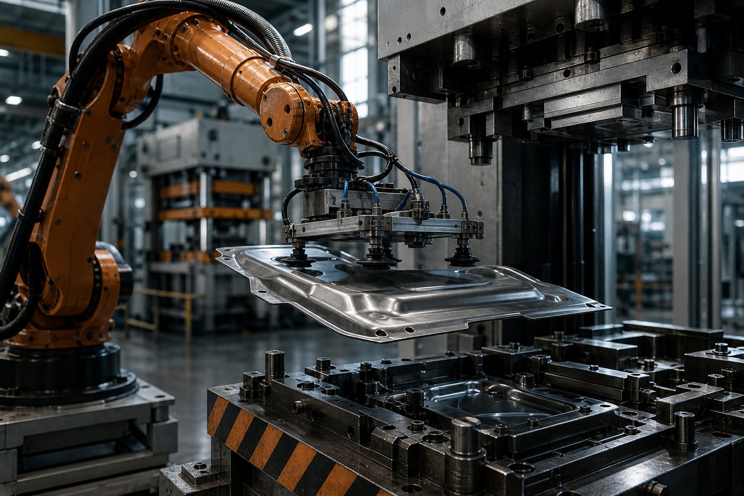
Fully robotic transfer represents the performance ceiling. Articulated six-axis robots or dedicated linear transfer units pick parts from one die, reorient them if needed, and place them precisely into the next station's locating nest. Yaskawa's press tending data indicates that a tandem press operation - one robot loading from the front, another unloading from the back - averages one part every 6.5 to 8 seconds, translating to roughly 450 to 550 parts per hour. A single robot handling both sides extends cycle time slightly to 7.5 to 9 seconds per part. These rates represent a significant throughput advantage over manual handling, with far greater repeatability.
The following table breaks down how these three approaches compare across the factors that matter most on a production floor:
Factor | Manual Transfer | Semi-Automated | Fully Robotic |
|---|---|---|---|
Cycle Time Range | 10-15 sec/part | 8-12 sec/part | 6.5-9 sec/part |
Part Placement Consistency | Low - operator dependent | Medium - gravity/conveyor dependent | High - repeatable to fractions of a millimeter |
Labor Requirements | 1-2 operators per station | 1-2 operators for full line | 0 operators in cycle; 1 technician monitoring |
Capital Investment | Low | Moderate | High |
Changeover Flexibility | High - operators adapt quickly | Moderate - conveyors may need repositioning | Moderate to High - requires reprogramming and EOAT swap |
Part Size/Weight Handling | Limited by ergonomic safety | Moderate - conveyor capacity limits | High - die stamping support for large parts up to robot payload |
Ideal Application | Low-volume, prototype, or short runs | Mid-volume, simple geometries | High-volume, complex or heavy parts |
The ROI calculation isn't purely about speed. As JR Automation points out, robotic transfer also eliminates the repetitive injury risk inherent in manual press tending - a factor that makes recruiting and retaining workers increasingly difficult. When you factor in reduced scrap from consistent placement, fewer misalignment defects, and the ability to run lights-out shifts, robotic systems often justify their higher upfront cost within 12 to 24 months on high-volume programs.
End-of-Arm Tooling and Gripper Design
The robot itself is only half the equation. What matters just as much - sometimes more - is what's attached to the end of its arm. End-of-arm tooling (EOAT) is the interface between the robot and the workpiece, and in a line die environment, that interface must adapt to a part that changes shape at every station.
Imagine station one produces a shallow-drawn cup, station three delivers a fully formed housing with flanges, and station five yields a trimmed and pierced final part. The gripper that picks up a flat blank at the beginning of the line can't use the same contact strategy for a deep, flanged shell three stations later. This is why transfer stamping operations often require station-specific EOAT or adaptable gripper designs that accommodate evolving part geometry.
Three gripper families dominate press line automation:
- Vacuum grippers: The most common and flexible option. Vacuum cups mounted on adjustable extrusions conform to part surfaces and can be repositioned to handle different geometries. They work well for flat blanks and gently curved panels but lose effectiveness on heavily perforated or oily parts where seal integrity suffers.
- Magnetic grippers: Effective for destacking and handling ferrous blanks, magnetic systems grip without requiring a flat sealing surface. However, they add weight to the end effector - a concern when moment and inertia limits constrain how much payload the robot can move at speed. They also can't handle aluminum, stainless steel, or any non-ferrous material.
- Mechanical grippers: Clamp-style or finger-based grippers excel where vacuum and magnets fall short - perforated parts, complex 3D shapes, and situations where the part edge provides the only reliable gripping surface. As IMTS reports, mechanical grippers are ideal for wavy or oily workpieces where vacuum cups simply cannot maintain suction.
In practice, many line die operations use hybrid tooling that combines vacuum cups with mechanical backup fingers. The cups handle initial pickup, while the fingers secure complex formed features that develop as the part progresses through the line. Quick-change coupling systems - either lever-actuated manual clamps or automatic tool changers - allow operators or robots to swap EOAT during die changeovers, keeping downtime to minutes rather than hours.
Press Synchronization and Cycle Time Optimization
Here's where line die automation gets truly challenging. Unlike a transfer press where all stations share a single ram and cycle in unison, a tandem line die setup uses independent presses - each with its own motor, clutch, and stroke timing. Getting four to eight separate machines to open, accept a part, close, form, open again, and release in a coordinated sequence requires precise synchronization.
The press cycle is measured in 360 degrees of rotation: zero degrees is top dead center (press fully open), 180 degrees is bottom dead center (press fully closed), and 360 degrees returns to fully open. The robot must enter the die space, place or retrieve a part, and exit completely - all within the open window between roughly 300 and 60 degrees. Entering too early risks a collision with a closing ram; exiting too late delays the next stroke.
Modern press line controllers coordinate this timing by networking all presses and robots through a unified control system. Encoder feedback from each press crank tells the controller exactly where each ram sits in its cycle, and the robots receive real-time clearance signals before entering the die space. Robots can even release parts 0.5 to 1 inch above the die surface - provided the lower die has proper nesting features - shaving fractions of a second off each transfer and boosting overall line throughput.
Cycle time optimization in a synchronized line follows a simple principle: the slowest station dictates the pace of the entire line. If station four requires an extra half-second for a deep draw operation, every other press must wait. Engineers address this by matching press speeds to forming requirements at each station - servo-driven presses can slow through the working portion of the stroke for heavy draws while accelerating through the non-working portion, maintaining high average strokes per minute without compromising part quality.
Consistent part orientation is the hidden payoff of well-synchronized automation. When a robot places every blank into the same locating nest at the same angle, station after station, the cumulative positional error that plagues manual operations virtually disappears. This precision becomes especially critical in later stations where pierced holes and trimmed edges must align with features formed upstream - a misplaced part at station two doesn't just produce one bad feature; it cascades through every remaining operation.
Automation solves the consistency problem between stations, but what about the consistency problem within each station? Even with perfect part placement and synchronized presses, the forming process itself can introduce defects - springback, wrinkling, tearing - that require their own set of diagnostic tools and corrective strategies.
Troubleshooting Common Line Die Stamping Defects
Perfect automation, flawless synchronization, and optimized press speeds still can't guarantee a defect-free part. The forming process itself pushes sheet metal to the edge of its mechanical limits at every station - stretching it, compressing it, shearing it - and sometimes the material pushes back. Springback warps dimensions. Wrinkles ripple across draw walls. Tears open where stress concentrates. Each of these failures carries a fingerprint that, if you know how to read it, points directly to its root cause.
What makes defect troubleshooting in line die stampings distinct from progressive die work? In a progressive die, the part remains attached to the carrier strip, which constrains and stabilizes the workpiece throughout forming. In a line die setup, the blank is a free-standing workpiece - unsupported between stations, subjected to handling forces during transfer, and re-fixtured at every stop. That independence amplifies certain defect modes, particularly those related to material flow control, blank positioning, and cumulative dimensional drift across stations.
Springback and Dimensional Distortion
Imagine bending a piece of sheet metal to 90 degrees, releasing the punch, and watching the angle open back to 92 or 93 degrees. That elastic recovery - the material's stubborn insistence on returning partway to its original shape - is springback, and it's the single most persistent dimensional defect in metal stamping die design.
Springback occurs because sheet metal deformation is never purely plastic. A portion of the strain energy stored during forming releases the instant the punch retracts, causing the part to "relax" away from the die geometry. The effect intensifies with higher-strength materials: a mild steel bracket might spring back 1 to 2 degrees, while an AHSS component can bounce 5 to 8 degrees or more. As Die-Matic notes, springback is especially common in high-strength materials like HSLA when dies don't account for material elasticity.
In a line die configuration, springback compounds across stations. A part that springs back slightly after the initial draw arrives at the restrike station with altered geometry - the restrike die then compensates based on an assumed incoming shape that no longer matches reality. This cascading mismatch is less of an issue in progressive dies, where the carrier strip anchors the part and limits its freedom to distort between operations.
The primary corrective strategy is overbend compensation: designing the die to form the material past its target angle so that elastic recovery brings it to the correct final position. As Henli Machine explains, engineers must "anticipate springback" during the die design phase by reserving a corresponding springback compensation angle. For severe cases, a dedicated restrike station - an extra stop in the line - applies a corrective hit that locks the geometry into place. Selecting materials with a lower elastic modulus or using corrective bending processes also reduces the effect.
Wrinkling, Tearing, and Thinning in Draw Operations
These three defects are deeply interconnected - fix one aggressively and you risk triggering another. They represent the fundamental tension in every deep draw operation: controlling material flow so it's neither too free (wrinkling) nor too restricted (tearing), while keeping wall thickness uniform throughout (avoiding thinning).
Wrinkling appears as wave-like folds or creases, most commonly along the flange or sidewall of a drawn part. It happens when compressive forces in the blank exceed the material's buckling resistance - essentially, there's more metal trying to flow into the die cavity than the cavity can accommodate smoothly. Insufficient blank holder force is the usual suspect. When the binder doesn't clamp the flange tightly enough, the unsupported material buckles under compression. An oversized blank exacerbates the problem by feeding excess material into a space that can't absorb it. In line die setups, each draw station has its own independently adjustable cushion system, which means blank holder pressure can be fine-tuned station by station - a significant advantage over progressive dies where binder force adjustments affect the entire strip.
Tearing is the opposite failure mode. When the material in the cup wall or sidewall can't stretch enough to accommodate the draw depth, tensile stress exceeds the metal's ultimate strength and a crack opens. Sharp die radii concentrate stress at the punch nose or die entry radius, acting as initiation points for fracture. Excessive draw ratios - trying to pull too much depth in a single station - are another common cause. Henli's technical breakdown recommends increasing the drawing coefficient to make deformation more gradual, selecting materials with superior plasticity, and optimizing lubrication. For deep parts, splitting the draw across multiple stations with intermediate annealing restores ductility between hits - a workflow that line die configurations handle naturally since each station is independent.
Thinning is subtler than tearing but just as dangerous. Instead of a visible crack, the material simply gets thinner in high-stress zones - typically at the punch nose radius and along the upper sidewall. You might not catch it visually, but a thickness gauge reveals localized reductions of 20% or more. Poor lubrication increases friction between the punch and the blank, preventing the material from sliding freely over forming surfaces. Excessive draw depth without adequate material support produces the same result. The corrective path involves improving lubrication coverage (both sides of the blank, as tool and die stamping experts consistently emphasize), increasing draw radii to spread stress over a larger area, and redistributing forming across additional stations.
Surface Defects and Galling Prevention
Surface quality often separates a usable part from scrap - especially for visible components like appliance panels or automotive body parts. Galling is the most insidious surface defect in die metal stamping because it's progressive: once it starts, it accelerates with every press stroke.
Galling occurs when friction between the die surface and the workpiece generates enough heat for microscopic welding - material from the blank transfers to the tool surface, building up rough deposits that score every subsequent part. Art Hedrick, writing in The Fabricator, identifies three types: abrasive galling (tool steel wears from the abrasive nature of the stamped material), adhesive galling (metallurgically similar surfaces generate friction and micro-weld together), and corrosive galling (chemical reactions from lubricant compounds attack the tool surface). Adhesive galling dominates in aluminum and stainless steel work because these materials share metallurgical similarities with common tool steels.
A telling example: D2 tool steel contains high chromium content. Stainless steel is also chromium-rich. When a D2 die section forms stainless steel, the chrome-to-chrome interface creates excessive friction and heat, leading to adhesive failure. The Fabricator's guidance is clear - rather than asking "what tool steel can withstand the friction," ask "how can I reduce the friction?" The first place to look is lubricant type and application. Ensuring both sides of the blank are lubricated - a step that's surprisingly often skipped - makes a measurable difference. Beyond lubrication, switching to a metallurgically dissimilar die material, such as aluminum bronze inserts, can outperform even coated tool steel by eliminating the root cause rather than just resisting the symptom.
For line die setups specifically, galling risk varies station by station. Early draw stations see the heaviest material-to-tool contact and generate the most friction heat, making them prime candidates for coated inserts and aggressive lubrication. Trim and pierce stations, by contrast, encounter brief shearing contact that generates less sustained friction but can still cause abrasive galling over long production runs. The ability to tailor surface treatments independently at each station - coating the draw die with TiAlN while leaving the trim die with a simpler nitrided surface - is one of the practical advantages of the line die approach over a monolithic progressive tool where every station shares the same die block material.
The following table consolidates each major defect type with its visual signatures, root causes, and the corrective actions that metal die stamping professionals rely on to restore part quality:
Defect Type | Visual Indicators | Root Causes | Corrective Actions |
|---|---|---|---|
Springback | Part angles open beyond target; walls bow outward; flanges deviate from specified geometry | Elastic recovery inherent to material; insufficient overbend in die design; high-strength materials amplify effect | Add overbend compensation angles to die; insert dedicated restrike station; use CAE simulation to predict and pre-correct; select lower elastic modulus material where possible |
Wrinkling | Wave-like folds on flange edges or sidewalls; compression-induced buckling visible on draw surfaces | Insufficient blank holder force; oversized blank feeding excess material; die fillet radii too small causing resistance | Increase blank holder (binder) pressure; optimize blank size to match draw geometry; polish die fillet radii; add draw beads to control material flow |
Tearing | Visible cracks or splits at punch nose radius, die entry radius, or along sidewall; often at thinnest wall section | Excessive draw ratio for single station; sharp die radii concentrating stress; poor lubrication restricting material flow; insufficient material plasticity | Split draw across multiple stations; increase die and punch radii; improve lubrication on both blank surfaces; add intermediate annealing for deep parts; select more ductile material grade |
Thinning | Localized wall thickness reduction (detectable by ultrasonic or micrometer measurement); may not be visible without gauging | Excessive friction at punch/blank interface; draw depth exceeding material capacity in one hit; inadequate lubrication coverage | Apply lubricant to both blank surfaces; increase punch nose radius; redistribute forming across additional stations; use forming simulation to identify high-strain zones before production |
Galling | Scoring or scratching on part surface; adhesive buildup visible on die surfaces; progressive surface degradation worsening with each stroke | Metallurgical similarity between tool steel and workpiece (adhesive); abrasive nature of stamped material (abrasive); chemical attack from lubricants (corrosive); insufficient or incorrect lubrication | Switch to dissimilar die material (e.g., aluminum bronze inserts); apply PVD coatings (TiN, CrN, TiAlN) to die surfaces; upgrade lubricant type and ensure both-side application; increase die surface polish quality |
A few patterns emerge from this table that are worth highlighting. First, lubrication appears as a corrective action for nearly every defect - it's the single most underappreciated variable in metal stamping. Second, adding stations is a recurring solution for tearing, thinning, and springback, which is precisely why line die setups suit complex forming sequences. Adding a restrike or redistribution station is straightforward when each die is independent; in a progressive tool, that same change might require redesigning the entire strip layout.
Third - and this is often missed - several of these defects interact. Increasing blank holder force to eliminate wrinkling can push the process toward tearing if the material doesn't have sufficient ductility. Coating a die surface to prevent galling changes friction conditions, which in turn alters material flow patterns and may shift wrinkling or thinning behavior. Effective troubleshooting in line die operations means treating the process as a system, not addressing individual defects in isolation.
Knowing how to diagnose and correct these defects is essential shop-floor knowledge. But the broader strategic question - whether a line die setup is the right choice for your specific part, volume, and material in the first place - requires a different kind of analysis, one that weighs part geometry, production economics, and industry application demands against each other.
When to Choose Line Die Stampings for Your Application
Recognizing stamping defects and knowing how to fix them is valuable - but it's far more valuable to know whether a line die setup is the right process before you ever build a single tool. The wrong process choice doesn't just cause defects; it locks you into a cost structure, a cycle time, and a flexibility profile that no amount of troubleshooting can undo.
So how do you decide? The answer comes down to five measurable criteria - part size, draw depth, geometric complexity, material thickness, and annual volume - each of which draws a boundary between line die territory and the domains of progressive or transfer die alternatives. Think of it as a practical checklist: if your part checks two or more of these boxes, line die stampings likely deserve serious evaluation.
Part Size, Depth, and Complexity Thresholds
The simplest litmus test is this: can your part physically travel through a progressive die on a carrier strip? If the answer is no - because the part is too wide, too deep, or too geometrically complex to remain attached to coil stock - then you've moved beyond progressive die territory.
Among the various types of stamping dies, line die configurations excel specifically when:
- Part dimensions exceed strip-feed limits: Components wider than approximately 300-400 mm or with overall dimensions that prevent efficient nesting on a coil strip are natural candidates. Automotive body panels, large structural brackets, and appliance housings routinely fall into this category.
- Draw depth requires multiple stages: Parts with depth-to-diameter ratios exceeding 0.75:1 typically can't be formed in a single hit, and deep-drawn features are incompatible with continuous strip feeding. Each draw, redraw, and restrike gets its own station in a line die setup.
- Geometry demands multi-angle forming: Components requiring cam-driven flanges, undercuts, or forming operations from directions other than the vertical press stroke need dedicated stations with independent cam mechanisms - something far easier to engineer across separate die sets than within a single progressive tool.
- Material thickness exceeds 2.0-3.0 mm: Heavier gauges generate forming forces that strain progressive die strip carriers and require higher tonnage than a single press can economically deliver across all stations. Line die setups match each station's press tonnage to its specific forming load.
- The part is a free-standing blank, not a nested profile: If your finished component is a three-dimensional shell, cup, or enclosure rather than a flat profile with bends, strip feeding offers no advantage - and wastes significant material in carrier webbing.
When sourcing partners - whether progressive die stampings suppliers or transfer die stampings suppliers - evaluate your part, these geometric thresholds are the first filters they apply. A part that exceeds progressive die limits but fits within a single large press bed might route to a transfer die. A part that requires separate presses for tonnage distribution or that involves extremely deep draws across many stages points to a full tandem line die arrangement.
Volume and Cost Considerations
Geometry tells you whether line die stamping can produce your part. Volume tells you whether it should.
Line die tooling occupies a middle ground in the cost landscape. Individual die sets for each station cost less than a complex progressive die - a single draw station might run $15,000 to $50,000, whereas a 20-station progressive tool can reach $200,000 to $500,000. But multiply that per-station cost by six or eight stations, add automation hardware, and factor in press line infrastructure, and the total investment can equal or exceed a progressive die program.
The economic sweet spot for line die stampings generally falls in the mid-to-high volume range - roughly 10,000 to 500,000+ parts annually. Below 10,000 units, the tooling investment across multiple stations is hard to amortize. Above that threshold, the per-part cost drops steadily as fixed tooling costs spread across more units. For long run progressive stamping programs exceeding several hundred thousand parts per year, the decision comes down to geometry: if the part fits a progressive die, strip-fed speed usually wins on per-part economics. If it doesn't, line die or transfer die setups are the only practical path.
A critical but often overlooked cost factor is changeover flexibility. Line die setups allow individual stations to be modified or replaced without scrapping the entire tooling package. If your program anticipates mid-cycle engineering changes - common in automotive stamping die programs during vehicle development - this modularity can save tens of thousands of dollars in tooling rework compared to modifying a monolithic progressive die.
This is where upfront feasibility analysis pays for itself many times over. Rather than committing to a full tooling build only to discover that your part needs an additional station or a different press tonnage, manufacturers can validate die concepts through CAE simulation before cutting steel. YICHEN's stamping die solutions include feasibility analysis and CAE simulation services designed specifically for this purpose - helping engineers model material flow, predict station count requirements, and evaluate forming forces across the entire line before any tooling investment is finalized.
Industry Applications Where Line Dies Excel
Certain industries have gravitated toward line die stampings because their parts consistently hit the size, depth, and complexity thresholds outlined above. Understanding where this process dominates can help you benchmark your own application.
Automotive: Body panels - hoods, doors, fenders, floor pans - are the quintessential automotive stamping die application for line and transfer die setups. These parts are large, require deep draws, and demand multi-station forming sequences that progressive dies simply can't accommodate. Structural reinforcements, crossmembers, and transmission housing components also run frequently on tandem press lines. As Keysight's simulation team notes, line and transfer die stamping are the dominant metal forming processes for the automotive sector, with simulation now integral to validating these complex tooling setups.
Appliances: Washer tubs, dryer drums, refrigerator liner panels, and oven enclosures all require deep-drawn, large-format forming. These parts combine substantial draw depth with surface quality requirements that make station-by-station process control essential.
Industrial and electrical enclosures: Deep-drawn metal housings for electrical junction boxes, motor covers, and HVAC equipment often demand seamless construction with tight dimensional control - a combination that line die setups deliver through controlled multi-stage forming.
Heavy structural components: Thick-gauge brackets, frame reinforcements, and mounting plates for construction equipment and agricultural machinery require high tonnage and heavy die sets that are better distributed across individual presses than concentrated in a single progressive tool.
Across all these applications, the common thread is the same: the part's physical requirements - size, depth, thickness, or forming complexity - dictate the process. Line die stampings aren't chosen because they're simpler or cheaper in every case; they're chosen because they're the only stamping method that can produce the part at all, or the only one that can do so at production-worthy quality and volume.
For manufacturers navigating these decisions, engaging a tooling partner early in the evaluation process eliminates costly missteps. YICHEN's end-to-end stamping die capabilities - spanning feasibility studies, CAE-driven station configuration, and prototype validation - give sourcing managers and tooling engineers the data they need to commit confidently to a line die program. Rather than relying on rules of thumb, simulation-backed feasibility analysis quantifies forming risk and tooling cost before the first purchase order is issued.
Choosing the right process, however, is only the starting line. Translating that decision into production-ready tooling - from initial simulation through die machining, trial runs, and dimensional validation - involves its own rigorous engineering workflow, one where every phase builds on the decisions made here.
From Die Design to Production-Ready Line Die Tooling
You've selected line die stampings as your process, chosen your material, and defined your station count. What happens next? The gap between a validated concept and a production-ready stamp die set sitting in a press is where most tooling projects either accelerate or stall. Every phase in the die development workflow - from initial feasibility through final dimensional sign-off - carries compounding consequences. A shortcut at the simulation stage surfaces as a costly modification during tryout. A missed tolerance during machining cascades into weeks of bench fitting. Understanding this workflow end to end isn't just helpful for tooling engineers; it's essential knowledge for sourcing managers who need to evaluate supplier capability and manage program timelines.
Here's the complete development sequence, broken into the stages that every line die tooling program follows - whether you're building four stations or eight:
- Part feasibility review and DFM analysis
- Forming simulation and CAE analysis
- Die design and 3D modeling
- CNC machining of die components
- Die assembly and bench fitting
- Trial runs (T0/T1) with iterative adjustments
- Dimensional inspection and validation
- Production release and maintenance planning
Each stage feeds the next, and skipping or compressing any one of them almost always costs more time downstream than it saves upfront. Let's walk through what actually happens at each stop.
Feasibility Analysis and CAE Simulation
Before any steel is cut - before a single die component is modeled - the engineering team needs to answer a deceptively simple question: can this part actually be formed? Feasibility analysis examines the part's geometry, material grade, thickness, and draw depth against known forming limits to identify potential showstoppers early. This includes evaluating draw ratios, blank size estimates, likely station count, and press tonnage requirements at each station.
Think of it as a risk filter. A part with a 0.6:1 depth-to-diameter ratio in mild steel passes easily. The same geometry in DP 780 steel might require an extra redraw station and a significantly larger blank - realities that change tooling cost and press line layout before a single CAD file is opened.
CAE (Computer-Aided Engineering) simulation transforms this feasibility check from educated guesswork into quantifiable prediction. Using finite element analysis, engineers digitally replicate the entire forming sequence - deep drawing, trimming, flanging, restrike - and observe how the virtual blank behaves at each station. The software generates forming limit diagrams (FLD) that map strain distribution against the material's forming limit curve, flagging zones at risk of cracking (red), critical thinning (yellow), or compression-induced wrinkling (blue).
The practical payoff is enormous. Industry data shows that manufacturers implementing CAE simulation typically reduce physical tryout iterations by 30 to 50 percent. That means fewer die modifications, less wasted trial material, and a compressed development timeline. Springback prediction - one of the trickiest aspects of dies manufacturing for high-strength steels - can be modeled and compensated in the die surface geometry before machining begins, rather than discovered the first time a trial part pops out of the die two degrees off target.
CAE also validates station sequencing decisions. Should the trim happen before or after the restrike? Does the blank need draw beads at specific locations to control material flow? Will an intermediate annealing step be necessary between draw stations for stainless steel? Simulation answers these questions digitally, at a fraction of the cost of answering them on a physical press line. For dies in manufacturing environments where program timelines are measured in weeks rather than months, this front-loaded engineering effort is what separates on-time launches from costly delays.
YICHEN's stamping die development process begins at exactly this stage - feasibility analysis and CAE simulation run before any commitment to full tooling production, giving engineers and sourcing managers quantified confidence in the die concept rather than relying on assumptions that only reveal themselves during tryout.
Die Machining, Assembly, and Trial Runs
With simulation results validated and the die design frozen in 3D CAD, the project moves into physical execution. This is where the stamp die concept becomes a tangible tool - and where machining precision determines whether the simulation's predictions hold true on the shop floor.
Die component machining combines multiple processes to achieve the required geometries and surface finishes. CNC milling rough-cuts die shoes, punch plates, and die blocks from pre-hardened tool steel billets. Electrical discharge machining (EDM) - both wire and sinker - handles complex internal profiles, sharp corners, and features that conventional cutting tools can't reach. Precision grinding brings critical surfaces like die faces, punch tips, and guide post bores to final dimensional tolerances, often within microns. For a standard die set, every component must reference common datums - alignment holes, dowel pin locations, and guide post bores - so that the assembled tool achieves the same spatial relationships modeled in the CAD environment.
Heat treatment happens in parallel with or immediately after rough machining. Punches and die inserts undergo hardening to their target Rockwell values - typically RC 58-62 for tool steels like D2 or SKH9 - followed by tempering to balance hardness with toughness. Vacuum heat treatment minimizes distortion and surface oxidation, preserving the dimensional integrity that previous machining operations achieved. After heat treatment, finish grinding and EDM refine the hardened components to their final specifications.
Assembly brings all machined components together onto the die shoes. Bench fitting - the hands-on work of shimming, adjusting, and verifying the assembled die - is where a skilled die maker's experience proves irreplaceable. Guide posts are checked for perpendicularity. Punch-to-die clearances are verified with feeler gauges or measurement pins. Stripper travel is set, blank holder surfaces are blued and spotted for full contact, and every locating feature is confirmed against the 3D model.
Trial runs - commonly designated T0 (first tryout) and T1 (second tryout after corrections) - put the assembled die under real forming conditions for the first time. A small batch of blanks runs through each station while engineers evaluate part geometry, surface quality, material flow patterns, and dimensional accuracy. This is where simulation meets reality: most well-simulated dies produce T0 parts that are close to specification, but real-world variables - actual material batch properties, press deflection under load, lubrication distribution - introduce deviations that simulation can't fully capture. As a progressive die manufacturer or a line die builder, you expect to make adjustments after T0. The goal isn't perfection on the first hit; it's minimizing the gap between simulated prediction and physical result so that corrections are measured in tenths of millimeters rather than wholesale geometry changes.
Typical T0 corrections include shimming punch heights, adjusting blank holder pressure, recutting trim edges, and fine-tuning draw bead heights to redirect material flow. T1 trials verify that these corrections achieved the intended results. For complex line die programs with six or more stations, T0/T1 cycles at each station must be coordinated sequentially - a draw die modification at station two changes the incoming part shape for every downstream station, so the tryout process moves through the line in order.
Quality Validation and Production Release
A part that looks good coming off the trial press isn't necessarily production-ready. Dimensional validation bridges the gap between visual assessment and quantified conformance to engineering specifications.
Coordinate measuring machines (CMMs) remain the gold standard for point-to-point dimensional verification. A CMM probe touches specific datum features, hole locations, trim edges, and formed surfaces, comparing measured coordinates to the nominal 3D model. For line die stamped parts - which are often large and have complex 3D surfaces - CMM inspection can take hours per part, but provides measurement uncertainty down to a few microns.
Optical 3D scanning has emerged as a powerful complement to CMM work, especially for full-surface validation. Optical measurement systems capture millions of surface points in minutes, generating a complete digital twin of the stamped part that can be overlaid on the CAD model. Color-mapped deviation reports make it immediately obvious where the part conforms and where it drifts - a visual tool that's far more intuitive than a spreadsheet of CMM coordinates. For large automotive stamping dies, scanning systems can capture a 2.5-meter die surface in under 15 minutes, making them practical for both tryout and in-process inspection.
Go/no-go gauges and checking fixtures provide the fastest shop-floor verification. Custom-machined fixtures replicate the part's mating surfaces, datum locators, and critical feature positions. If the part seats fully into the fixture without interference and all check pins pass through their corresponding holes, the part conforms. These fixtures are especially valuable during production because they enable operators to verify parts in seconds rather than the minutes or hours required for CMM or scanning - catching drift before it produces a run of nonconforming parts.
Process capability analysis ties all of this together. Rather than measuring a single part, engineers measure a statistically significant sample - typically 30 to 50 consecutive parts - and calculate Cpk values for critical dimensions. A Cpk above 1.33 (or 1.67 for safety-critical automotive features) demonstrates that the process is both centered on the target dimension and sufficiently controlled to stay within tolerance over sustained production. As Ming Chiang's validation methodology illustrates, CPK analysis through continuous sampling confirms dimensional stability across millions of cycles - the ultimate proof that a die set is ready for release.
Only after dimensional validation and process capability confirmation does the tooling receive production release. At this point, the engineering team also establishes a maintenance SOP: scheduled inspection intervals (often every 50,000 to 100,000 strokes), planned sharpening for trim and pierce inserts, lubrication protocols, and replacement criteria for wear components like springs and guide bushings. Predictive monitoring - tracking press force signatures over time to detect gradual die degradation - is increasingly common on high-volume lines, allowing maintenance to be triggered by data rather than by a defective part.
This end-to-end workflow - feasibility, simulation, design, machining, assembly, tryout, validation, and release - is what separates a tooling program that launches on schedule from one that spirals into costly delays. Each phase requires specialized capabilities: CAE analysts who understand material behavior, machinists who hold micron-level tolerances, die makers who can translate simulation outputs into physical adjustments, and inspection teams who can validate conformance across complex 3D geometries.
YICHEN covers this complete lifecycle - from initial feasibility analysis and forming simulation through precision CNC machining, die assembly, trial runs, and final inspection. For sourcing managers and tooling engineers evaluating line die programs, partnering with a supplier that owns every stage of this workflow eliminates the coordination risk of splitting responsibilities across multiple vendors. It also means that lessons learned during CAE simulation feed directly into machining decisions, tryout corrections reflect simulation predictions, and inspection results close the loop back to the original die design - a fully integrated development process that de-risks tooling investment and accelerates the path from concept to production-ready parts.
Frequently Asked Questions About Line Die Stampings
1. What is the difference between line die stamping and progressive die stamping?
Line die stamping uses individual standalone dies at separate press stations, with pre-cut blanks transferred between them manually or robotically. Progressive die stamping feeds a continuous metal strip from a coil through multiple stations within a single die set, with the part staying attached to the carrier strip until final cutoff. Line dies handle larger parts, deeper draws, and heavier gauges, while progressive dies deliver faster cycle rates (30-60+ strokes per minute) for smaller, high-volume components. Choosing between them depends on part size, draw depth, production volume, and geometric complexity.
2. What types of parts are best suited for line die stampings?
Line die stampings are ideal for parts that are too large, too deep, or too geometrically complex for progressive die strip feeding. Common applications include automotive body panels (hoods, doors, fenders), appliance housings (washer tubs, dryer drums), deep-drawn electrical enclosures, and heavy-gauge structural brackets. Parts with depth-to-diameter ratios exceeding 0.75:1, widths beyond 300-400 mm, or those requiring multi-angle cam forming are strong candidates. Partnering with an experienced stamping die supplier like YICHEN for feasibility analysis and CAE simulation helps confirm whether line die tooling is the right fit before committing to investment.
3. How many stations does a typical line die stamping setup require?
A typical line die setup uses 4 to 8 individual stations, though the exact count depends on part geometry, draw depth, material grade, and feature complexity. A simple bracket may need only four stations (draw, trim, pierce, flange), while a deep-drawn automotive panel in advanced high-strength steel could require seven or eight stations including redraws, restrikes, and springback compensation hits. Harder materials like AHSS or stainless steel often add one or two extra stations compared to mild steel for the same part shape, due to work hardening and springback behavior.
4. What are the most common defects in line die stamping and how are they prevented?
The five most common defects are springback (elastic recovery distorting angles), wrinkling (compression buckling in draw flanges), tearing (tensile failure during deep draws), thinning (localized wall reduction), and galling (adhesive material transfer scoring part surfaces). Prevention strategies include overbend compensation and restrike stations for springback, optimized blank holder pressure for wrinkling, splitting draws across multiple stations for tearing, improved lubrication for thinning, and PVD coatings like TiN or CrN on die surfaces for galling. CAE simulation before die construction predicts most of these issues, reducing costly trial-and-error corrections.
5. How does automation affect line die stamping productivity and quality?
Automation dramatically improves both throughput and consistency. Manual transfer limits cycle rates to roughly 4-6 strokes per minute with variable part placement. Fully robotic transfer achieves 6.5-9 seconds per part with repeatable positioning accuracy to fractions of a millimeter, producing 450-550 parts per hour. Robotic systems use vacuum grippers, magnetic pickups, or mechanical fingers as end-of-arm tooling, with hybrid designs adapting to changing part geometry across stations. Press synchronization via networked controllers coordinates independent presses so robots enter and exit die spaces safely within tight timing windows, maximizing uptime while eliminating operator injury risk.


