


Why Choosing the Right Stamping Die Method Matters More Than Ever
You have a part design locked in, a target volume on the table, and a budget that leaves no room for a wrong call on tooling. The question lands on your desk: transfer die stamping or progressive die stamping? Search for an answer online and you'll find dozens of pages that define each process, yet almost none that help you actually choose between them based on your specific constraints.
That gap is expensive. Die stamping tooling represents a significant upfront commitment, often ranging from $8,000 to $25,000 or more for a custom progressive die alone. Pick the wrong method and you're looking at tooling that doesn't match your part geometry, scrap rates that eat into margins, or cycle times that bottleneck downstream assembly. This article takes a different approach. Instead of repeating textbook definitions, it ranks dies and stamping methods, including compound and hybrid configurations, against real-world production criteria so you can match your requirements to the right process with confidence.
Why the Transfer vs Progressive Decision Costs More Than You Think
Choosing incorrectly between transfer die stamping and progressive die stamping doesn't just waste tooling dollars. It cascades. An oversized progressive die for a part that should have been transfer-formed means you're fighting strip-width limitations and adding secondary operations. A transfer setup for a simple bracket that could run at high speed on a progressive press means slower throughput and higher per-part cost. The real expense isn't the die itself. It's the production inefficiency you live with for years because tooling, once built, defines your process. Understanding what is a progressive die and how it differs architecturally from a transfer die is the foundation of that decision, but the selection criteria go far beyond basic definitions.
Who This Guide Serves
This evaluation is structured for three distinct roles, each with different priorities when comparing die stamping approaches:
- Design engineers - You'll gain clarity on which method supports your part geometry, tolerance stacks, and forming complexity without forcing compromises in the CAD model.
- Procurement managers - You'll find a framework for evaluating tooling investment against total cost of ownership, lead time, and reorder economics rather than comparing quotes on price alone.
- Production managers - You'll see how each method maps to throughput targets, press compatibility, and quality consistency so floor-level decisions align with engineering intent.
The evaluation ahead scores each method, from standard progressive die stamping to transfer, compound, and high-speed variants, against criteria that actually drive supplier selection and long-term ROI. No single method wins universally. The right answer depends on where your part sits at the intersection of geometry, volume, and budget.
How We Evaluated and Ranked These Stamping Die Methods
A useful comparison of types of stamping dies needs more than a feature list. It needs a structured way to measure fit. Rather than declaring one process universally superior, we scored each method against criteria drawn from the practical constraints engineers and buyers actually face when specifying transfer tooling or progressive die tooling for a new program.
Selection Criteria We Used to Rank Each Method
Every stamping method in this evaluation is measured against seven decision factors. Think of these as the lenses through which a progressive tool and die investment, or any other tooling commitment, should be examined:
- Part geometry complexity - Can the method form the required 3D features, draw depths, and multi-axis bends without secondary operations?
- Production volume thresholds - At what annual quantity does the tooling investment break even and deliver competitive per-part cost?
- Tooling investment and ROI timeline - How much capital is required upfront, and how quickly does production volume recover that cost?
- Dimensional tolerance requirements - What level of positional accuracy and repeatability does the process reliably sustain over long runs?
- Material compatibility range - Does the process handle your specified alloy, thickness, and ductility characteristics without excessive wear or scrap?
- Secondary operation needs - Does the method consolidate downstream steps like tapping, welding, or deburring into the press cycle?
- Press equipment compatibility - Does your existing press tonnage, bed size, and feed system support the method without capital equipment additions?
How Scoring Works
No single progressive stamping tool or transfer die configuration wins across all seven criteria. Instead, each method earns a best-fit rating per criterion based on general engineering principles and published manufacturer specifications rather than fabricated benchmarks. Practical realities matter here too. Floor space limitations, operator skill levels, and whether your facility already runs a transfer press or a high-speed progressive press all influence which method delivers the most value without requiring a facility overhaul. The goal is matching your specific constraints to the process that scores highest where it counts most for your application.
Transfer Die Stamping for Complex Multi-Station Parts
When part geometry scores high on complexity, size, or multi-axis forming requirements, one method consistently rises to the top of the evaluation: transfer die stamping. It earns that position not because it's faster or cheaper per stroke, but because it removes the architectural constraints that limit every strip-based process.
What Makes Transfer Die Stamping Stand Out
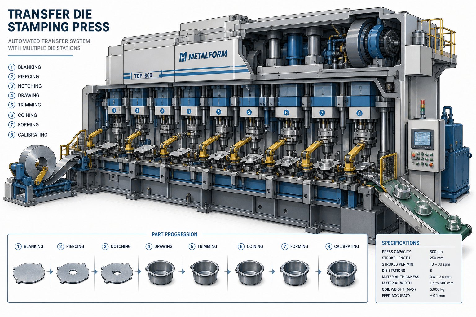
The fundamental distinction between transfer dies and progressive dies comes down to how the workpiece moves through the press. In a progressive setup, the part stays attached to a carrier strip throughout the forming sequence. In transfer stamping, the blank is separated from sheet stock at the first station and then robotically moved between independent die stations using mechanical arms or transfer bars. This is the part-carrier architecture versus the strip-carrier architecture, and it changes everything about what geometries are possible.
Because each station in a transfer die operates on a free-standing blank rather than a tethered strip, you gain several critical capabilities. There's no strip-width limitation dictating maximum part size. The blank can be rotated, flipped, or repositioned between stations, allowing forming on all sides of the part. Deep draws, asymmetric bends, and large structural features that would tear or distort a carrier strip become routine operations. And since robotic transfer ensures consistent part positioning at every station, repeatability stays stable across tens of thousands of cycles.
Transfer press tooling also achieves tolerance control within tight bands. Industry data suggests tolerances can be maintained within ±0.01mm in well-engineered setups, with production efficiency gains of 30-50% compared to single-operation stamping of the same parts.
Ideal Use Cases and Volume Fit
Transfer dies excel in scenarios where the part simply cannot exist on a progressive strip. Think automotive structural components like chassis brackets and cross members, appliance housings requiring deep-drawn forms, and large brackets needing multi-axis bends that no single-plane strip process can deliver. These parts typically exceed 300mm in one or more dimensions or involve depth-to-width ratios that would buckle a carrier strip.
The method also shines when secondary operations, such as in-press tapping, flanging, or trimming, can be consolidated into the transfer sequence, eliminating downstream handling. For manufacturers evaluating transfer stamping dies engineered specifically for multi-station forming with robotic transfer, suppliers like YICHEN focus on stable repeatability for complex parts across high-volume automotive and industrial programs.
Volume-wise, transfer die stamping fits best at production runs of 50,000 pieces and above, where the higher initial tooling investment is offset by consolidated operations and reduced per-part handling costs.
Pros
- Handles complex 3D geometry including deep draws and multi-axis forming
- Robotic transfer ensures consistent part positioning across all stations
- Supports larger blank sizes without strip-width constraints
- Integrates secondary forming and finishing operations in-line
- Stable repeatability over long production runs
Cons
- Higher initial tooling investment compared to progressive dies
- Slower cycle time versus high-speed progressive setups
- Requires a transfer press equipped with robotic or mechanical transfer systems
- More complex setup and changeover procedures
The trade-off is clear: transfer die stamping trades raw speed for geometric freedom. When your part demands that freedom, no amount of progressive-strip engineering can substitute for the architectural advantage of independent station forming. But when the geometry is simpler and volume targets push cycle time to the forefront, the calculus shifts toward a very different process architecture.
Progressive Die Stamping for High-Volume Precision Parts
Where transfer dies trade speed for geometric freedom, progressive dies flip that equation entirely. When parts are smaller, geometries are moderate, and volume demands push into the hundreds of thousands or millions, progressive stamping delivers the fastest path from coil stock to finished component with minimal handling in between.
How Progressive Die Stamping Achieves Speed
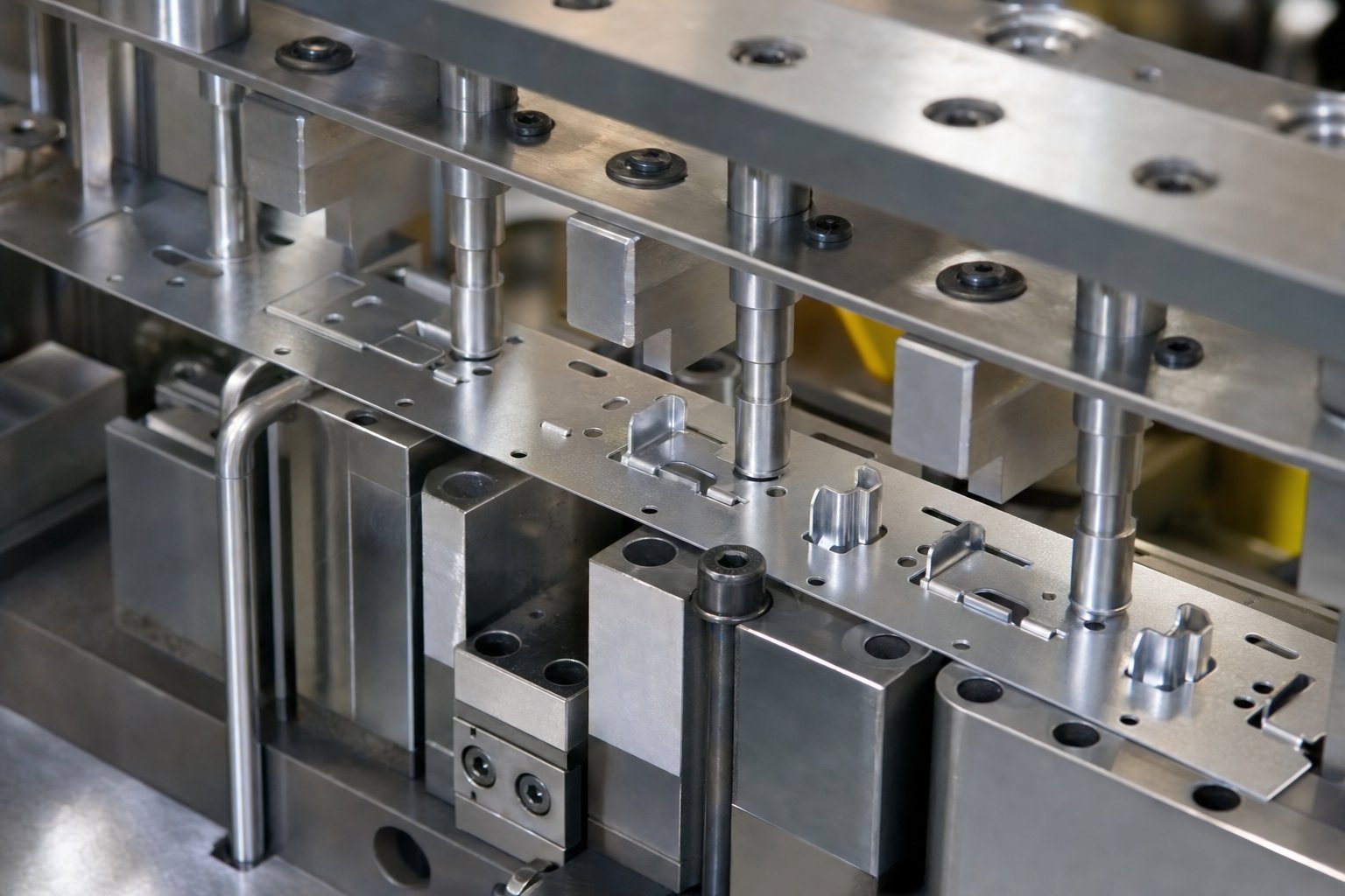
Imagine a continuous metal strip unrolling from a coil and feeding through a single die block that contains multiple stations arranged in sequence. With every stroke of the press, the strip advances one pitch length, and each station performs a different operation: blanking, piercing, forming, coining, or bending. The part takes shape incrementally, station by station, while remaining attached to the carrier strip until the final cutoff station separates it as a finished piece.
What keeps everything aligned across these stations? Pilot holes. Punched into the strip at the first station, these holes engage pilot pins at every subsequent station to lock the strip into exact position before each stroke lands. This mechanism is what gives progressive die metal stamping its positional accuracy, typically holding tolerances within ±0.01mm across the full forming sequence. The pilot-and-advance system also dictates strip utilization: the spacing between parts, bridge material, and pilot hole placement all consume strip width, which is why part size is inherently limited by the coil width the press can accommodate.
Because all operations happen within a single press cycle and the strip feeds continuously, progressive stamping dies can run at stroke rates far exceeding what transfer or compound methods achieve. High-volume production lines commonly sustain 200 to 600 strokes per minute for smaller components, with some configurations pushing beyond 1,000 SPM for simple geometries.
Where Progressive Dies Dominate
Progressive dies own the territory of smaller, repeatable parts produced at scale. Electrical connectors, terminals, spring clips, brackets under 300mm, shielding cans, and battery contacts are all textbook applications. These components share a profile: moderate geometric complexity, tight tolerances on pierced features, and annual volumes that justify the upfront investment in a precision progressive stamping die.
Progressive stamping materials span a wide range. Copper and brass are favorites for electrical components due to their conductivity and ductility. Stainless steel grades handle corrosion-sensitive applications. Carbon and alloy steels at thicknesses from 0.1mm to around 6mm cover structural brackets and automotive clips. Materials with good formability and consistent thickness tolerance perform best because the strip must survive multiple forming stations without cracking or springing out of alignment.
The single-press, continuous-feed architecture also means minimal part handling. No robotic transfer arms, no inter-station loading. The strip enters one end of the die and finished parts drop out the other. That simplicity translates directly into lower labor overhead, reduced handling damage, and fewer quality escapes tied to repositioning errors.
Pros
- Fastest cycle times of any stamping method, often exceeding 300 strokes per minute
- Lower per-part cost at high volumes due to continuous single-press operation
- Minimal part handling reduces labor and quality risk
- Pilot hole system delivers excellent positional repeatability across stations
- Wide material compatibility including copper, brass, stainless steel, and various carbon steels
Cons
- Part size limited to what fits within the strip width and press bed
- Geometry constrained to features that can form while the part remains attached to the carrier strip
- Longer tooling lead times for complex progressive dies with many stations
- Scrap bridge material between parts reduces net material utilization
- Deep draws and multi-axis forming are difficult or impossible without tearing the strip
Progressive metal stamping earns its ranking as the throughput champion for parts that fit its architectural envelope. But what happens when even standard progressive speeds aren't enough, when volumes climb into the tens of millions and part geometries shrink to micro-scale? That's where a specialized subset of this process pushes cycle rates to their mechanical limits.
High-Speed Progressive Die Stamping for Maximum Throughput
Standard progressive dies already outpace transfer and compound methods on cycle time. High speed progressive die stamping takes that advantage and pushes it to its mechanical ceiling, targeting applications where annual volumes reach tens of millions and every fraction of a second per stroke matters to unit economics.
When Standard Progressive Isn't Fast Enough
A typical progressive press runs comfortably between 200 and 600 strokes per minute. High-speed variants operate at 800 to over 1,000 strokes per minute, depending on part size and die complexity. That jump in speed isn't free. It demands engineering concessions across part design, material selection, and tooling durability.
Parts must be geometrically simpler. At elevated stroke rates, complex forming features introduce stress concentrations that cause cracking or dimensional drift before the strip even reaches the cutoff station. Shallow bends, simple piercing patterns, and minimal draw depths are the norm. Material must be thinner, typically under 1.0mm, and more ductile to accommodate rapid deformation without spring-back issues or edge fracturing.
Tooling takes the hardest hit. Punches and die inserts cycle hundreds of millions of times over their service life at these speeds, so they require premium tool steels with precision grinding, advanced coatings, and tighter maintenance intervals. Heat buildup from friction at high stroke rates also accelerates wear, meaning lubrication systems and die cooling become critical infrastructure rather than optional upgrades.
Material and Part Size Constraints
Not every alloy cooperates at high speed. The materials that perform best share two traits: good ductility and tight thickness tolerance across the coil. Copper progressive stamping dominates in electrical applications because copper's inherent softness and conductivity make it ideal for micro-connectors and contact springs stamped at extreme rates. Brass progressive stamping fills a similar niche where slightly higher strength and corrosion resistance are needed, such as precision terminal pins and socket contacts.
Stainless steel progressive stamping is feasible at high speed, though typically limited to thinner austenitic grades (301, 304) where ductility remains adequate. You'll find it in shielding components and spring contacts for electronics where corrosion resistance can't be sacrificed. Steel progressive stamping with low-carbon grades rounds out the material options for cost-sensitive high-volume parts like battery tabs and automotive micro-brackets.
Typical components produced at high speed include micro-connectors for consumer electronics, spring contacts in relay assemblies, EMI shielding cans, battery tabs for lithium-ion cells, and lead frames for semiconductor packages. These parts share a profile: small footprint, minimal forming depth, and production demands measured in millions per month.
Pros
- Maximum throughput, often exceeding 1,000 parts per minute
- Lowest achievable cost-per-part at extreme production volumes
- Ideal for thin-gauge conductive materials like copper and brass
- Automated continuous-feed operation minimizes labor input
Cons
- Very limited geometry complexity; deep draws and multi-axis bends are not viable
- Higher tooling wear rates demand more frequent maintenance and replacement
- Requires premium press equipment with precision feed systems and die protection sensors
- Restricted to thinner materials, typically under 1.0mm
- Heat management and lubrication systems add infrastructure cost
High-speed progressive stamping occupies a narrow but highly profitable lane: simple parts, extreme volumes, thin ductile materials. Step outside those boundaries and the method's limitations become liabilities rather than trade-offs. For parts that need exceptional edge quality or tight concentricity on flat blanks without any forming at all, an entirely different single-stroke approach offers advantages that neither progressive nor transfer methods can match.
Compound Die Stamping for Flat High-Precision Components
Not every stamped part needs multi-station forming or high-speed strip feeding. Some components are geometrically flat, yet demand dimensional accuracy that progressive or transfer processes struggle to guarantee on every edge simultaneously. That's where compound die stamping enters the picture, offering single-stroke precision that solves a very specific problem better than any multi-station alternative.
Single-Stroke Precision for Flat Parts
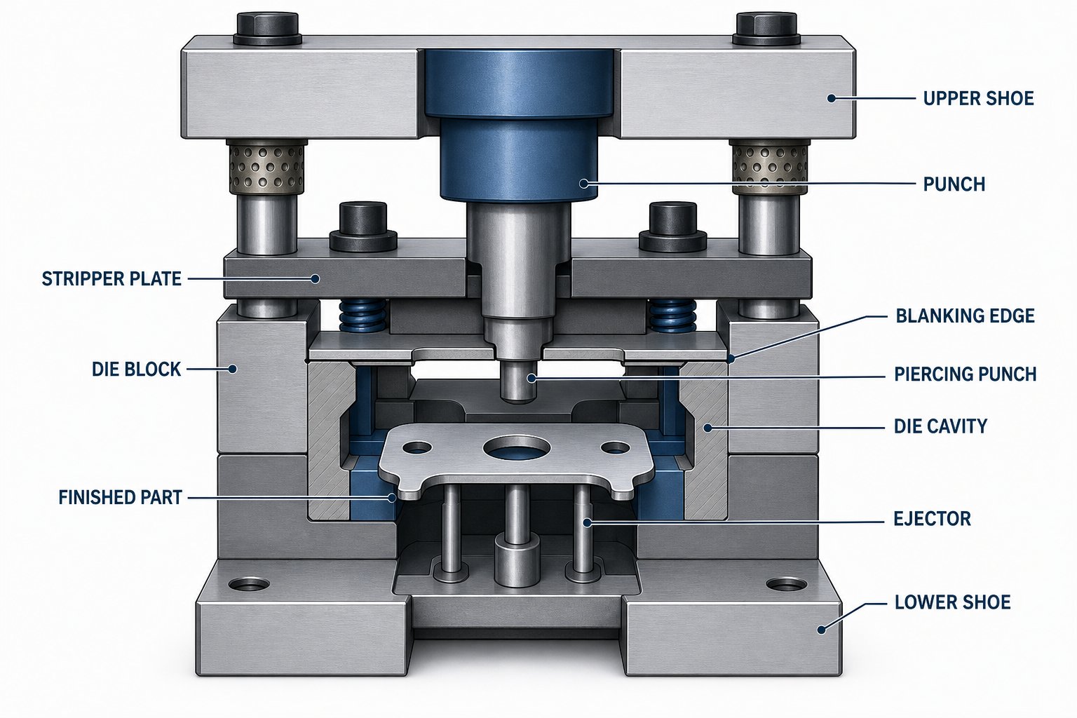
A compound die performs blanking and piercing in one press stroke. Picture this: the punch descends, the outer profile is blanked, and all internal holes are pierced at the same instant. Because every cut happens simultaneously within a single die stamping press cycle, there's no strip advancement between operations, no cumulative positioning error, and no opportunity for the workpiece to shift between stations.
The result is superior flatness and edge concentricity compared to progressive methods. In a progressive die, the strip advances between stations, and even with pilot holes providing alignment, small positional variations can accumulate. A compound die eliminates that variable entirely. The relationship between each pierced hole and the outer blank edge is locked in by the tool geometry itself, not by strip registration.
There's another advantage that often goes unmentioned. Because the part is cut from both sides simultaneously, with the punch acting from above and the die applying counter-pressure from below, burr-side inconsistency is eliminated. Progressive blanking produces a burr on one side of each cut that alternates depending on whether the operation is a punch-through or a trim. Compound dies produce a consistent edge condition across the entire part perimeter, reducing or removing the need for secondary deburring.
When Compound Dies Beat Progressive and Transfer
Compound die stamping earns its spot when parts are geometrically simple but demand exceptional dimensional accuracy on all features relative to the blank edge. Typical applications include:
- Washers and shims requiring tight ID-to-OD concentricity
- Flat terminals and bus bars with precise hole-to-edge relationships
- Laminations for electric motors where stacking accuracy depends on per-piece flatness
- Gaskets and sealing rings needing uniform edge quality
- Precision shims with thickness and planarity requirements beyond what progressive methods reliably deliver
From a cost perspective, compound die tooling is less expensive to develop than complex progressive die tooling because there are fewer stations and no strip-feed mechanism to engineer. For medium-volume production of simple flat parts, this cost difference is significant. You get precision die stamping performance without the capital outlay associated with multi-station tooling or transfer press infrastructure.
Volume fit sits in the medium range. Compound dies produce one part per stroke, so they can't match progressive throughput rates. But for runs of 10,000 to 500,000 pieces where the geometry is flat and tolerances are demanding, the math often favors a compound die over a progressive setup that's overbuilt for the part's actual complexity.
Pros
- Excellent flatness and concentricity from simultaneous cutting on all features
- Lower tooling cost than progressive dies for geometrically simple parts
- Consistent edge quality without burr-side variation
- High degree of repeatability for single-die operation
- Well suited for medium production volumes where per-part cost and precision both matter
Cons
- Limited to flat geometry with no forming, bending, or drawing capability
- One part per stroke limits throughput compared to progressive strip feeding
- Not suitable for 3D features or multi-axis forming
- Larger parts slow cycle time as blanks take longer to clear the die
Compound dies occupy a focused niche: flat parts, tight tolerances, moderate volumes, minimal tooling investment. They won't replace progressive or transfer dies for complex geometry, but for the right application they deliver precision that multi-station processes can only approximate. Of course, real-world manufacturing rarely fits neatly into a single-method box. Many programs require elements from more than one process, which opens the door to hybrid strategies that blend the strengths of different approaches.
Hybrid and Alternative Stamping Approaches Worth Considering
Sometimes the part on your screen doesn't cooperate with any single process. The geometry is too complex for a compound die, too flat for deep drawing, too thick for high-speed progressive, and too small to justify a full transfer press setup. That's not a failure of analysis. It's a signal that a hybrid or alternative approach deserves a serious look.
When to Consider Fine Blanking or Deep Drawing Instead
Fine blanking fills a gap that progressive and compound dies leave open: parts needing full-shear edge quality across the entire cut surface without secondary machining. Where a standard progressive die stamping process produces a cut edge with roughly 25-60% shear and the remainder fracture zone, fine blanking squeezes the part from the strip in a cold-extrusion-like action that yields smooth, square edges with minimal fracture. Think gears, levers, and locking components in automotive transmissions where edge condition is critical to function.
Deep drawing enters the conversation when your part's depth-to-diameter ratio exceeds what transfer die stations can form in a reasonable number of operations. Cylindrical housings, cup-shaped enclosures, and containers where depth equals or exceeds the part's diameter push beyond transfer die capabilities and into territory governed by material flow physics rather than station count. The limiting draw ratio, typically 1.8 to 2.0 for a first draw, sets a hard boundary that no amount of tooling sophistication can override.
Combining Methods for Optimal Results
Real production floors rarely run a single process in isolation. Manufacturers routinely combine a progressive stamping process for pre-forming, piercing, and partial blanking with a die transfer operation that finishes the part across independent stations. This progressive-to-transfer handoff is common in automotive programs where a flat blank needs high-speed piercing followed by deep multi-axis forming that would destroy a carrier strip.
Progressive stamping and fabrication workflows offer another practical bridge. A progressive die handles the high-speed portion, stamping features that benefit from strip-based efficiency, and then parts move to downstream fabrication cells for welding, tapping, or assembly operations that no in-die process can replicate economically. This approach works especially well when existing press equipment supports progressive tooling but the facility lacks a transfer press, or when floor space constraints make a dedicated transfer line impractical.
The decision triggers that point toward alternative or hybrid approaches tend to be specific and measurable:
- Edge condition specifications require full-shear quality across all cut surfaces (fine blanking territory)
- Depth-to-diameter ratio exceeds 1:1, making deep drawing mandatory regardless of volume
- Part requires both high-speed piercing and multi-axis forming that no single die architecture handles efficiently
- Existing press equipment doesn't support the ideal single-method solution, and capital budget won't cover new machinery
- Floor space or operator skill constraints rule out adding a transfer press line
- Volume is too low to justify full progressive or transfer tooling, but part complexity exceeds compound die capability
Hybrid strategies aren't a compromise. They're an engineering optimization. When you stop forcing a part into a single-method box and instead map each feature to the process that forms it best, total cost of ownership often drops even though the workflow appears more complex on paper. The key is knowing when that complexity pays for itself, which requires a structured side-by-side comparison of every method against your actual production variables.
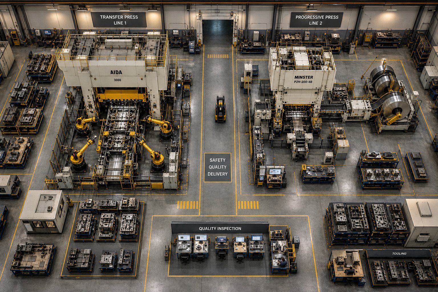
Complete Stamping Method Comparison at a Glance
You've seen each method evaluated individually. The strengths, trade-offs, and ideal scenarios are clear in isolation, but real selection decisions don't happen in isolation. They happen when you're staring at a part drawing and asking which column this component falls into across multiple criteria simultaneously. A side-by-side view compresses that decision into something you can reference in minutes rather than re-reading five separate evaluations.
Side-by-Side Feature Comparison
The table below scores all five stamping methods across the seven criteria used throughout this evaluation. Whether you're sizing up a progressive die press for high-volume connectors or weighing a transfer stamping press for structural components, this is the consolidated view that aligns part requirements to process capability in one place.
| Criteria | Transfer Die Stamping | Standard Progressive Die Stamping | High-Speed Progressive Die Stamping | Compound Die Stamping | Hybrid / Alternative |
|---|---|---|---|---|---|
| Part Size Range | Medium to very large; no strip-width limitation | Small to medium; constrained by strip width and press bed | Very small to small; micro-components dominate | Small to medium flat parts | Varies by combined methods used |
| Geometry Complexity | High: deep draws, multi-axis forming, asymmetric shapes | Low to moderate: bends, piercing, shallow forms on carrier strip | Very low: simple piercing, shallow bends only | Low: flat blanking and piercing, no 3D forming | High: leverages best method per feature |
| Production Speed | Moderate: 20-80 strokes/min typical | Fast: 200-600 strokes/min | Very fast: 800-1,500+ strokes/min | Moderate: one part per stroke | Varies; often moderate overall |
| Tooling Investment | High: multiple independent die stations plus transfer mechanism | Medium to high: multi-station single die block | High: precision-ground tooling with advanced coatings | Low to medium: single-station die | Medium to high: multiple tool sets required |
| Ideal Volume Range | 50,000 to 1,000,000+ parts/year | 100,000 to 10,000,000+ parts/year | 1,000,000 to 100,000,000+ parts/year | 10,000 to 500,000 parts/year | Depends on configuration; typically medium-high |
| Material Versatility | Broad: steel, aluminum, stainless, copper alloys at varied thicknesses | Broad: 0.1mm-6mm; steel, copper, brass, stainless | Narrow: thin ductile materials under 1.0mm | Moderate: sheet metals suitable for flat blanking | Broad: each stage matched to optimal material handling |
| Tolerance Capability | Tight: ±0.01mm achievable with robotic positioning | Tight: ±0.01mm via pilot hole registration | Good: ±0.02-0.05mm; speed limits precision ceiling | Very tight: simultaneous cutting eliminates cumulative error | Depends on process combination; can achieve very tight |
A few patterns stand out. If your priority is geometric freedom, the table pushes you left toward transfer dies. If speed and per-part economics dominate, you drift right toward progressive die and stamping variants. Compound dies carve out a specific lane for flat precision work where multi-station complexity is overkill. And hybrid approaches cover the cases where no single column satisfies all seven rows.
Decision Matrix by Application Scenario
The feature comparison tells you what each method can do. The decision matrix below tells you which method to reach for based on what you're actually making. Match your application scenario to the recommended process:
| Application Scenario | Recommended Method | Why It Fits |
|---|---|---|
| Automotive structural parts (brackets, cross members, large housings) | Transfer Die Stamping | Multi-axis forming on large blanks; integrates secondary ops in-press |
| High-volume electrical connectors, terminals, micro-contacts | High-Speed Progressive Die Stamping | Maximum strokes/min for simple thin-gauge parts at extreme volumes |
| Flat precision laminations, washers, shims, gaskets | Compound Die Stamping | Single-stroke concentricity and flatness without cumulative error |
| Medium-complexity brackets, clips, shielding cans under 300mm | Standard Progressive Die Stamping | Balanced speed, cost, and moderate geometry on a progressive stamping press |
| Complex parts needing fine-blanked edges or deep draws beyond transfer limits | Hybrid / Alternative Approach | No single method handles full feature set; progressive pre-form + secondary finishing |
Notice that the decision matrix doesn't ask "which process is best?" in the abstract. It asks "what are you making, in what quantity, and what tolerances matter?" That reframe is what separates a confident tooling decision from an expensive guess.
Process selection depends on the intersection of part geometry, volume requirements, and total cost of ownership rather than any single factor. A progressive die press wins on speed but loses on geometry. A transfer stamping press wins on complexity but costs more per stroke. The right answer lives where your specific constraints overlap, not in a universal ranking.
These comparison tables give you a reference point, but a reference point only works if you know where your own project sits on each axis. The final step is translating this matrix into a prioritized decision sequence that accounts for the mistakes engineers most commonly make when locking in a stamping method.
Final Recommendations and Common Selection Mistakes
Comparison tables and feature matrices give you clarity, but they don't make the decision for you. What closes the gap between analysis and action is a prioritized sequence, a set of if-then rules that filter your part requirements through the most impactful constraints first. Below is the decision logic that manufacturing engineers and procurement buyers can apply directly to their next tooling program, followed by the mistakes that most commonly derail the selection process.
Match Your Part Requirements to the Right Process
Work through this sequence from top to bottom. The first condition your part satisfies is your starting point for tooling evaluation:
- If the part exceeds strip-width feasibility or requires multi-axis forming - Transfer die stamping is your primary candidate. Parts that need deep draws, rotation between stations, or blank sizes that no coil width can accommodate belong here. Transfer dies eliminate the carrier-strip constraint entirely, giving you geometric freedom that progressive architectures cannot replicate. For engineers evaluating transfer stamping dies for complex multi-station programs, YICHEN's transfer stamping die solutions offer robotic transfer systems designed for stable repeatability across large or asymmetric parts.
- If the part is small with high-volume demand and simple-to-moderate geometry - Progressive die stamping delivers the best per-part economics. Strip-fed continuous operation at 200-600+ strokes per minute makes this the throughput champion for brackets, clips, terminals, and connectors that fit within standard coil widths.
- If the part is flat with tight concentricity requirements and no 3D forming - A compound die gives you simultaneous blanking and piercing in a single stroke, eliminating cumulative positioning error. Washers, laminations, shims, and flat terminals with critical hole-to-edge relationships land here.
- If volume is extreme and geometry is minimal - High-speed progressive die stamping at 800-1,500 strokes per minute targets micro-connectors, battery tabs, and contact springs where unit counts reach tens of millions per year and part features are limited to shallow forms and simple piercing.
- If no single method satisfies all requirements - Hybrid approaches combining progressive pre-forming with transfer finishing, or progressive stamping with downstream fabrication, bridge the gaps. This is the right call when edge-quality specs demand fine blanking, when depth-to-diameter ratios push into deep-draw territory, or when existing equipment constraints rule out the ideal single-method solution.
This hierarchy isn't arbitrary. It's ordered by the constraint that's hardest to engineer around. You can always slow down a process or spend more on tooling, but you cannot force a part that exceeds strip-width limits into a progressive die no matter how much budget you throw at it. Geometry feasibility gates the decision first, volume and economics refine it second.
Common Mistakes to Avoid When Selecting a Stamping Method
Even experienced teams fall into patterns that inflate cost or compromise quality. Here are the misconceptions that surface most often when sourcing progressive die stampings or transfer die programs:
- Assuming progressive is always cheaper. Per-part cost at volume? Often yes. Total program cost? Not necessarily. A progressive die built with 15 stations to approximate geometry that a 6-station transfer die handles cleanly can end up costing more in tooling development, maintenance, and scrap. The strip material wasted on bridge connections and pilot holes adds up quickly on thick or expensive alloys. Transfer dies, as noted by MetalForming Magazine, often achieve better material utilization because they aren't restricted by strip progression layout.
- Overlooking tooling lifecycle costs. Initial die price is one number. Maintenance intervals, sharpening frequency, insert replacement, and eventual rebuilds tell the full story. A high-speed progressive die running at 1,000 SPM wears faster than a standard progressive setup. Progressive die stamping services that quote low piece prices without disclosing expected maintenance cadence can mislead procurement teams comparing proposals from transfer die stampings suppliers on a like-for-like basis.
- Ignoring secondary operation savings. Transfer dies consolidate forming, trimming, tapping, and flanging into a single press cycle. If your current progressive setup produces parts that immediately move to a deburring cell, then a tapping station, then a bending fixture, the labor and handling costs of those secondary steps may exceed the tooling premium of a transfer die that performs them in-line. Always calculate total landed cost, not just stamping cost.
- Selecting based on existing equipment alone. Owning a progressive stamping press doesn't mean every new part should run progressive. If the geometry genuinely demands transfer forming, forcing it into existing equipment leads to compromised tolerances, excess scrap, or a bloated progressive die that's expensive to maintain. Equipment availability should inform the decision, not dictate it.
- Underestimating lead time differences. Complex progressive die metal stamping services typically quote longer tooling lead times than equivalent transfer setups because multi-station strip dies require more iterative tuning during tryout. If time-to-market matters, the simpler die construction of transfer or compound approaches can shave weeks off the launch schedule.
The thread connecting all these mistakes is the same: treating the stamping method decision as a single-variable problem. It's never just about speed, or just about tooling cost, or just about geometry. It's about the intersection of all three, weighted by your specific production reality. Engineers who evaluate that intersection methodically, using the criteria and decision sequence outlined above, avoid the costly rework cycles that come from guessing.
FAQs About Transfer Die Stamping vs Progressive Die Stamping
1. What is the main difference between transfer die stamping and progressive die stamping?
The core difference lies in how the workpiece moves through the press. In progressive die stamping, the part stays attached to a carrier strip and advances through stations with each press stroke. In transfer die stamping, the blank is separated from sheet stock early and robotically moved between independent die stations. This architectural distinction determines what geometries each method can produce. Transfer dies handle larger, more complex 3D parts because the free-standing blank can be rotated, flipped, and formed on all sides. Progressive dies achieve faster cycle times because the continuous strip feed eliminates the need for robotic handling between operations.
2. When should I choose transfer die stamping over progressive die stamping?
Choose transfer die stamping when your part exceeds strip-width feasibility, requires deep draws, multi-axis forming, or asymmetric geometries that cannot form while attached to a carrier strip. Transfer dies are the better fit for automotive structural components, appliance housings, and large brackets over 300mm in any dimension. They also make sense when you can consolidate secondary operations like tapping, flanging, or trimming into the press cycle, reducing downstream handling costs. Suppliers like YICHEN specialize in transfer stamping dies with robotic transfer systems designed for stable repeatability across complex multi-station programs.
3. What production volume justifies progressive die stamping vs transfer die stamping?
Progressive die stamping typically becomes cost-effective at volumes above 100,000 parts per year, with per-part cost advantages growing significantly at volumes exceeding one million annually. Transfer die stamping generally requires volumes above 50,000 pieces per year to offset its higher initial tooling investment. However, volume alone does not determine the right choice. A part that requires multi-axis forming will cost more to force into a progressive die regardless of volume, because the added stations, scrap, and secondary operations erode the per-stroke speed advantage. Total landed cost, including secondary operations and scrap, matters more than piece price alone.
4. What are the tolerance capabilities of progressive and transfer die stamping?
Both methods can achieve tight tolerances of approximately plus or minus 0.01mm in well-engineered setups, though they accomplish this through different mechanisms. Progressive dies maintain positional accuracy via pilot holes punched into the strip at the first station, which engage pilot pins at every subsequent station to lock the strip position before each stroke. Transfer dies rely on robotic or mechanical transfer systems that position the free-standing blank consistently at each independent station. For flat parts requiring the tightest concentricity between pierced features and outer edges, compound dies may outperform both because simultaneous blanking and piercing eliminates cumulative positioning error entirely.
5. Can progressive and transfer die stamping be combined in one production process?
Yes, hybrid approaches that combine progressive pre-forming with transfer finishing are common in real-world manufacturing. Automotive programs frequently use a progressive die for high-speed piercing and initial blanking, then transfer the partially formed blank to independent stations for deep multi-axis forming that would destroy a carrier strip. Progressive stamping paired with downstream fabrication operations like welding, tapping, or assembly is another practical hybrid. These combined workflows make sense when no single die architecture handles the full feature set efficiently, or when existing press equipment supports one method but not the other.


