


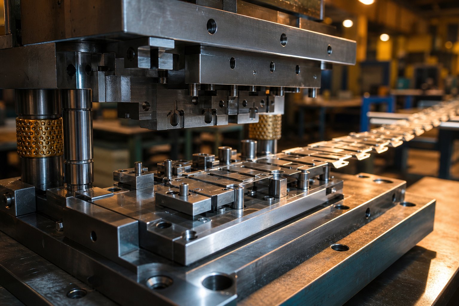
Decide Which Die Type Fits Your Part and Production Volume
Building a metal stamping die starts long before any steel gets cut. You begin with a finished part and work backward, reverse-engineering its geometry into tooling that can reproduce it thousands or millions of times under press load. That reverse-engineering step is the core of die-making, and it begins with one fundamental decision: which type of stamping die matches your part, your volume, and your budget.
So what are dies, exactly? In the simplest terms, a die is a precision tool that shapes sheet metal through cutting, forming, or both during a stamping press stroke. Understanding what is dies in manufacturing helps clarify why the choice of die type matters so much. The wrong choice leads to wasted tooling investment, excessive per-part cost, or quality issues that haunt you through production.
Three primary types of stamping dies cover the vast majority of applications: single-station, compound, and progressive.
Single-Station vs Compound vs Progressive Dies
Each die type occupies a different zone in the complexity-volume-cost landscape. Here is how they compare:
| Die Type | Ideal Part Complexity | Typical Annual Volume | Relative Tooling Cost |
|---|---|---|---|
| Single-Station | Simple (one operation per stroke: blank, pierce, or form) | Low to moderate (prototype through 50K) | Low |
| Compound | Moderate (multiple simultaneous cuts in one stroke, flat parts) | Moderate to high (50K to 500K+) | Medium |
| Progressive | High (multi-step sequences: cut, form, bend across stations) | High (100K to millions) | High |
Single-station metal stamping dies work best when you need one operation per hit, keeping tooling simple and setup fast. Compound dies combine operations like blanking and piercing into a single stroke, delivering tighter tolerances between features because everything is cut simultaneously. Progressive stamping dies feed a metal strip through multiple stations in sequence, producing a completed part with every press cycle at high speed.
Match Your Die Choice to Budget and Equipment Access
Your shop-floor capabilities heavily influence which path makes sense. If you have CNC milling and wire EDM in-house, building a single-station or simple compound die is realistic. Progressive metal stamping dies, with their complex strip layouts and multi-station timing, often require specialized design experience and equipment that pushes teams toward outsourcing specific operations.
This article covers the full spectrum, from hand-fitted prototype dies to production-grade progressive tooling. Whether you plan to machine every component yourself or outsource heat treatment and EDM work, the process of turning a part drawing into a working stamping die follows the same logical sequence. The first variable that shapes every downstream decision is the tool steel you select for each die component.
Select the Right Tool Steel Grades for Punches and Die Blocks
Tool steel is not a one-size-fits-all category. Each component in a stamping die faces different stress profiles: punches endure compressive shock and abrasive wear on every hit, die blocks resist sliding contact along cutting edges, strippers manage cyclic fatigue, and backup plates absorb distributed load. Choosing the right stamping tool material for each role directly controls how long your die runs between regrinds and how consistent your parts remain over a production campaign.
With complex production tooling often requiring investments of USD $100,000 to $500,000, selecting the wrong steel grade is an expensive mistake. You will either burn through budget on premature failures or over-specify material where it is not needed. The goal is matching wear resistance, toughness, and hardness to each component's actual service condition.
Tool Steel Selection Criteria by Die Component
Five steel grades (plus carbide) cover the majority of steel stamping dies in production. Here is how they map to real applications:
| Steel Grade | Typical Hardness (HRC) | Primary Wear Property | Best-Fit Application |
|---|---|---|---|
| D2 | 58-62 | Excellent abrasion resistance | Blanking punches, die sections for mild steel and brass |
| A2 | 57-62 | Balanced wear and toughness | Forming punches, medium-volume piercing, general-purpose die sections |
| S7 | 54-58 | High shock/impact resistance | Heavy forming punches, thick-stock operations, high-impact stations |
| M2 | 62-65 | Hot hardness, edge retention at speed | High-speed progressive stations, small piercing punches |
| Carbide (tungsten) | 70-75+ | Extreme abrasion resistance | Ultra-high-volume inserts (millions of hits), abrasive metal for stamping |
D2 remains the workhorse for general blanking and piercing in metal stamping materials selection. Its high chromium and carbon content delivers exceptional abrasion resistance, but it can chip under severe impact. When a punch faces heavy shock loading, such as piercing thick stainless steel stamping stock, A2 provides better toughness at a slight sacrifice in wear life. S7 takes that trade-off further, absorbing repeated impact where D2 or A2 would fracture. M2, a high-speed steel, retains its hardness even as progressive die stations generate heat at elevated cycle rates.
How Material Choice Affects Die Life and Maintenance Intervals
The relationship between hardness and hit count is not linear. A D2 punch at HRC 60 blanking mild steel might deliver 100,000 to 150,000 hits before burr height signals a needed regrind. That same punch cutting stainless drops to 30,000-50,000 hits due to the work-hardening nature of the sheet metal, which can approach the hardness of the tooling itself. Aluminum stamping presents a different challenge: the softer sheet does not wear edges as fast, but galling (material adhesion to the die surface) becomes the primary failure mode.
This is where coatings change the economics. PVD-applied titanium nitride (TiN) adds a hard, low-friction layer that extends die life significantly for mild steel work. For stainless steel metal stamping and aluminum metal stamping, titanium carbonitride (TiCN) outperforms TiN by reducing the chemical affinity between the sheet and tool surface. Studies on advanced high-strength steels show that PVD-coated tools can produce over 1.2 million parts compared to 50,000 for chrome-plated alternatives under the same conditions.
Imagine running a progressive die at 60 strokes per minute on stainless. Without TiCN coating, you are pulling the die for maintenance every shift. With it, you might run a full week. That difference in uptime often justifies the coating cost many times over, especially when you factor in lost production during die changes.
Powder metallurgy (PM) tool steels offer yet another tier. Their fine, evenly distributed carbide structure delivers both high wear resistance and impact toughness that conventional ingot-cast grades cannot match. In one documented case, switching from D2 to a PM grade at the same hardness increased tool life from 5,000-7,000 cycles to over 40,000 cycles when forming high-strength steel.
Steel grade and coating selection set the foundation. The next challenge is translating your part geometry into the precise punch and die shapes that will produce it, and that work happens in the CAD/CAM environment where clearances, strip layouts, and station sequences all take shape.
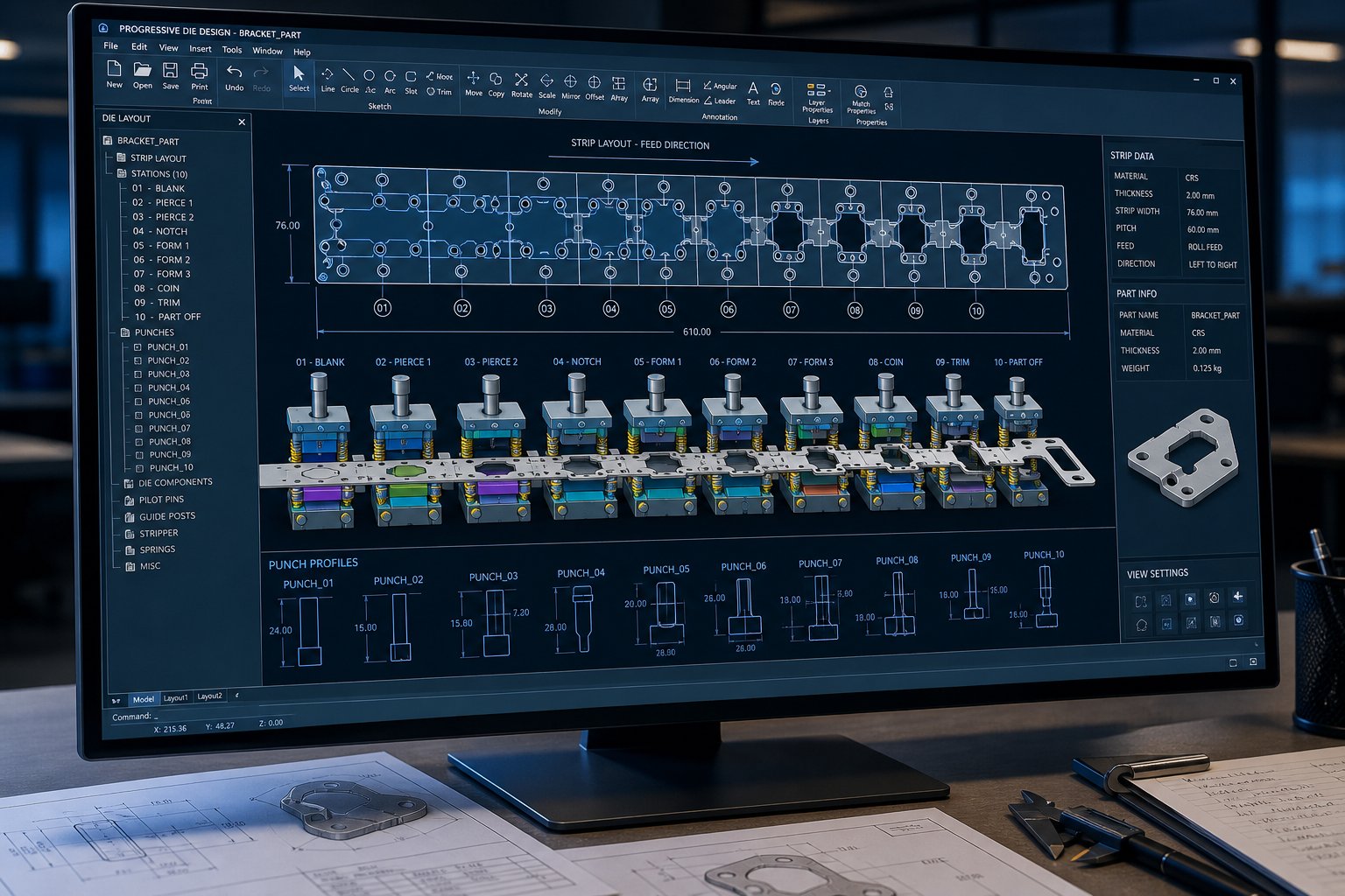
Design Die Geometry and Strip Layout Using CAD-CAM Simulation
You have your tool steels selected. The next question is: what exact shapes do those steels need to become? This is where stamping die design moves from material science into geometry, and it is the step that separates a working die from an expensive paperweight.
The workflow starts with your finished part drawing. You already know the material type and thickness. From those two inputs, you derive the single most critical dimension in any cutting die: punch-to-die clearance.
Clearance is the gap between the punch cutting edge and the die button cutting edge, expressed as a percentage of material thickness per side. Get it right, and you produce clean shear with minimal burr. Get it wrong, and you face excessive burrs, premature punch wear, slug pulling, or even fractured tooling. The recommended clearance varies by material because harder, higher-tensile-strength metals need more room for the fracture planes to align cleanly through the sheet thickness.
Punch-to-Die Clearance Chart for Common Sheet Metals
When planning your metal stamping die design, use these clearance ranges as starting points. Fine-tune based on your specific tolerance requirements and tooling condition.
| Sheet Material | Thickness Range | Recommended Clearance (% per side) | Notes |
|---|---|---|---|
| Mild Steel (low carbon) | 0.5 - 3.0 mm | 8 - 12% | Standard baseline; increase toward 12% for longer tool life |
| Stainless Steel (304/316) | 0.5 - 2.5 mm | 10 - 15% | Work-hardening increases cutting force; tighter clearance raises burr risk |
| Aluminum (5052, 6061) | 0.5 - 3.0 mm | 5 - 8% | Softer material allows smaller gap; watch for galling on die surfaces |
| Brass (C26000) | 0.5 - 2.0 mm | 5 - 8% | Clean shear at lower clearances; forgiving material for prototype dies |
One of the most practical stamping design tips to remember: modern tooling research suggests that running toward the higher end of these ranges (11-20% per side for steel) can significantly reduce tooling strain during piercing and increase operational life, even if it slightly increases burr height. You are trading a minor secondary deburr step for dramatically longer regrind intervals.
For the punch dimension, subtract the clearance from each side when you want to hold a hole size to the die. When you want to hold a blank size, add the clearance to the punch. This is fundamental sheet metal stamping design logic that drives every CAD model you build downstream.
Building Strip Layout and Station Sequence in CAD
For progressive sheet metal stamping dies, the strip layout is your roadmap. It defines how raw coil stock transforms into finished parts station by station. Think of it as a timeline: each station performs one or two operations, and the strip advances a fixed pitch distance between hits.
A solid strip layout addresses five elements:
- Pilot holes - Punched in the first station and used by pilot pins in subsequent stations to register the strip precisely. Without them, cumulative feed error ruins feature-to-feature accuracy.
- Carrier strip width - The material connecting your part to the coil as it travels through the die. Too narrow and it tears; too wide and you waste material.
- Station spacing (pitch) - Must be uniform and account for the largest station footprint plus adequate separation for structural integrity in the die plates.
- Negative and positive bypass notches - In sheet metal stamping dies, these notches relieve material adjacent to bends and forms, preventing interference as the part takes shape while remaining attached to the carrier.
- Scrap optimization - Nesting parts or adjusting strip width to maximize material utilization. Even a 2-3% improvement in yield compounds into major savings at high volumes.
Your CAD system builds this layout as a flat representation first, then each station gets modeled in 3D to verify that punches, lifters, and forming tools do not collide with each other or with the strip as it progresses.
Here is where metal stamping design moves from drafting into engineering validation. CAE simulation using finite element analysis lets you virtually form, bend, and cut your part before any steel is machined. The software predicts material thinning, wrinkling, and springback, flagging problems that would otherwise surface only during costly physical tryouts. Industry best practice follows a systematic strategy: measure springback in simulation, mitigate it through process modifications, control variability, and then compensate die surfaces accordingly. This approach has been proven to significantly reduce tryout iterations and ensure consistent dimensional compliance over a panel's production life.
For teams without in-house FEA capability, simulation services from experienced die makers can accelerate this validation phase considerably. YICHEN's stamping die services, for example, include feasibility analysis and CAE simulation as early-phase offerings, helping engineers validate die geometry and strip layouts before committing to machining. This front-loads problem-solving into the digital phase where changes cost hours instead of weeks.
The payoff of thorough stamping design work in CAD and simulation is straightforward: fewer surprises when hardened steel hits sheet metal for the first time. Every clearance calculated, every station sequenced, and every springback mode predicted in software is one less iteration burned in the tryout press. With geometry validated and strip layout locked, the focus shifts to transforming those digital models into physical die components through precision machining.
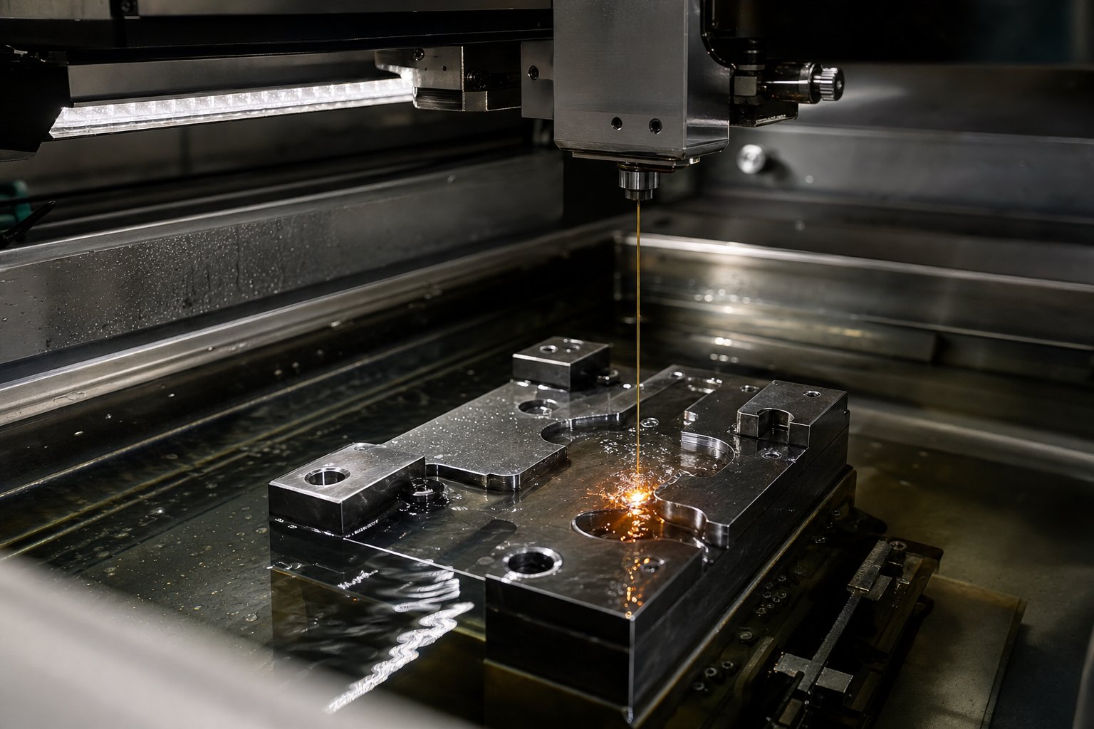
Machine Die Components With CNC Milling and Wire EDM
Your CAD models are locked. Strip layouts are validated. Every clearance is calculated to the hundredth of a millimeter. Steel blanks sit on the shop floor waiting to become precision stamping tooling. This is the phase where digital geometry becomes physical metal, and the sequence you follow determines whether those components fit together with micron-level accuracy or require hours of hand fitting.
The die process for machining follows a deliberate order: rough CNC milling removes bulk material from die blocks and punch holders, precision surface grinding brings critical surfaces to flatness and parallelism, and wire EDM cuts the complex profiles and tight-tolerance openings that define your cutting and forming geometry. Each operation builds on the last, and skipping or reordering steps creates compounding problems downstream.
CNC Milling Strategy for Die Blocks and Punch Profiles
Roughing is about speed, not precision. You are removing as much material as possible per unit time while leaving a controlled stock allowance for finishing passes. Modern high-speed roughing strategies like adaptive milling (also called trochoidal milling) use a small radial engagement at large axial depth, maintaining constant chip load throughout the cut. This approach extends tool life by 50-200% compared to conventional full-width slotting, which matters significantly when you are hogging out hardened tool steel hour after hour.
A critical decision appears early in the stamping machining workflow: do you soft-machine before heat treatment, or hard-mill pre-heat-treated blanks?
- Soft machining first - Mill your die blocks and punch profiles in the annealed state (typically HRC 20-25), where cutting is faster, tool wear is lower, and you can use more aggressive parameters. You then send parts out for heat treatment and return to finish-grind to final dimensions afterward. This is the traditional approach and remains cost-effective for most metal stamping tooling projects.
- Hard milling pre-hardened blanks - Start with blanks already heat-treated to working hardness (HRC 58-62). Modern CNC centers with rigid spindles and ceramic or CBN inserts can rough and finish hardened D2 or A2 directly. This eliminates the dimensional distortion caused by heat treatment, reducing the stock allowance needed for finish grinding. The trade-off is slower material removal rates and higher insert costs during roughing.
Regardless of which path you choose, standard practice calls for leaving 0.010-0.020 inches per side as finish stock after roughing on milled surfaces. This allowance ensures the finishing pass cuts cleanly below the roughed surface's work-hardened layer and any geometric errors from the roughing operation. Going thinner risks the finish tool alternating between cutting and rubbing, degrading both surface quality and dimensional consistency.
For the finishing passes, parameters shift dramatically. Feed rates drop to 30-60% of roughing values, depth of cut shrinks to 0.010-0.030 inches, and cutting speed increases by 10-20%. The goal is no longer material removal rate but rather surface finish and dimensional accuracy. A fresh cutting edge is mandatory for finishing, as a worn insert produces rougher Ra values and introduces dimensional drift that can push tight-tolerance features out of spec.
Pocket features, guide pin bores, dowel holes, and spring pockets all come off the CNC mill. But the defining profiles of a stamping die, the cutting edges, slug openings, and intricate forming contours, demand a different technology entirely.
Wire EDM and Sinker EDM for Complex Die Geometry
Wire EDM transformed tool and die stamping. Before its widespread adoption, die makers relied on jig grinding, hand fitting with files and stones, and hours of bench work to achieve the profiles and clearances that wire EDM now cuts in a single setup. Imagine spending a full shift hand-fitting a complex die opening to match a punch profile, checking with Prussian blue, scraping, re-checking. That same geometry today comes off a wire EDM machine holding tolerances of 0.0001 inches or tighter, with a surface finish that often needs no further work.
Understanding when to use wire EDM versus sinker EDM is essential for efficient tool stamping metal projects:
| Feature | Wire EDM | Sinker EDM |
|---|---|---|
| Best geometry type | Through-profiles, slug openings, 2D contour cuts | Blind cavities, 3D forming surfaces, complex mold shapes |
| Cutting tool | Thin brass or coated wire (as fine as 0.020 mm) | Custom-shaped graphite or copper electrode |
| Typical tolerance | 0.0001 in. (0.0025 mm) or better | 0.0001 in. (0.0025 mm) |
| Surface finish | Smoother; achievable Ra < 0.2 um with skim passes | Slightly rougher; may need post-finishing |
| Setup cost | Lower (wire is a standard consumable) | Higher (custom electrode must be machined first) |
| Ideal die application | Die button openings, punch profiles, stripper inserts | Draw cavities, coining inserts, 3D form punches |
In a typical blanking or piercing die, wire EDM handles the lion's share of precision work. It cuts the die button openings that define part outlines, shapes punch profiles from hardened tool steel blanks, and produces the slug relief openings below cutting edges. Because the wire passes completely through the workpiece, every cut is inherently a through-profile, which aligns perfectly with the through-holes and openings that dominate cutting die geometry.
Sinker EDM earns its place in tool stamping operations that require three-dimensional forming surfaces. A draw punch with compound curves, a coining insert with textured surfaces, or a form cavity with draft angles and radii that cannot be reached by a wire all call for a custom-machined electrode that "sinks" its shape into the die steel. The trade-off is time and cost: each electrode must be CNC-machined (often from graphite), and the electrode itself wears during the process, sometimes requiring multiple electrodes for a single cavity.
Surface finish on die components directly impacts both part quality and die longevity. Rough surfaces create friction that accelerates adhesive wear, particularly when stamping stainless or aluminum. Industry best practice recommends Ra values below 0.2 um (approximately a 600-grit finish) on working die surfaces before applying any coating. For cutting edges, wire EDM skim passes can achieve this level directly. For forming surfaces machined by sinker EDM or CNC milling, additional polishing or lapping brings the finish into the target range. Punches and die sections that will receive PVD coatings demand this surface preparation, as coatings amplify any underlying roughness rather than masking it.
The precision achieved during industrial metal stamping machining sets tight constraints on what comes next. Even the most accurately machined D2 die block is still in its soft or intermediate state if you followed the soft-machining path, and the metallurgical transformation that gives it working hardness introduces its own dimensional shifts. Managing those shifts through controlled heat treatment and post-hardening finishing is the next critical link in the chain.
Heat Treat Die Steels and Apply Protective Coatings
A machined die block sitting on your bench at HRC 20 is not a working die component. It looks right, it measures right, but it lacks the hardness and wear resistance to survive even a few hundred press strokes. Heat treatment is the metallurgical transformation that converts soft, machinable tool steel into a working surface capable of producing hundreds of thousands of stamped steel or stamped aluminum parts without dimensional drift.
The process is straightforward in concept but unforgiving in execution. Every grade has specific temperature windows, quench requirements, and tempering protocols. Deviate, and you get cracking, excessive distortion, or inconsistent hardness that leads to premature die failure.
The full heat treatment cycle follows four stages:
- Stress relief after rough machining - Aggressive material removal during CNC milling introduces internal stresses that can cause warping during austenitizing. Stress relieving at approximately 1200-1250°F (below the steel's critical temperature) relaxes these locked-in stresses before the real transformation begins. This step is especially important for intricate die components or unbalanced cross-sections.
- Austenitizing (high-heat soak) - The steel is brought to its specific austenitizing temperature and held there long enough for the crystal structure to fully transform. A rule of thumb is one-half hour per inch of thickness with a 45-minute minimum. Temperature is the more critical variable here. Never exceed the upper range for any grade, as overheating causes erratic results including low as-quenched hardness and dimensional instability.
- Quenching - The transformed steel must be cooled rapidly enough to form martensite, the hard but brittle structure that gives tool steel its cutting ability. The quench medium is grade-specific and non-negotiable.
- Tempering (multiple passes) - Quenched steel is dangerously brittle. Tempering at controlled temperatures reduces internal stress and balances hardness against toughness. Air-hardening grades like D2 and A2 require a double temper, while high-speed steels like M2 need a triple temper, with the part cooled to approximately 125°F between each cycle.
Heat Treatment Cycles for Common Die Steel Grades
Each steel grade used in stamping steel dies follows its own thermal recipe. Running the wrong cycle on the wrong grade produces unpredictable results, from soft spots that wear prematurely to through-cracking that scraps the entire component.
| Steel Grade | Austenitizing Range | Quench Medium | Tempering Range | Target Working Hardness (HRC) |
|---|---|---|---|---|
| D2 | 1010-1030°C (1850-1890°F) | Air | 200-540°C (400-1000°F) | 58-62 |
| A2 | 940-980°C (1725-1800°F) | Air | 175-540°C (350-1000°F) | 57-62 |
| S7 | 940-955°C (1725-1750°F) | Air (interrupted oil for large sections) | 205-620°C (400-1150°F) | 54-58 |
| O1 | 790-815°C (1450-1500°F) | Oil (heated to 100-125°F) | 175-315°C (350-600°F) | 57-62 |
| M2 | 1190-1230°C (2175-2250°F) | Interrupted oil or salt bath at 540°C | 540-595°C (1000-1100°F), triple temper | 62-65 |
Notice that S7, the shock-resistant grade used for heavy forming punches, will not develop full hardness in larger sections unless given an interrupted oil quench, even though it is classified as air-hardening. This is one of those details that trips up shops without deep heat treatment experience.
Distortion during heat treatment is inevitable. Metallurgical transformation combined with thermal expansion shifts dimensions on every component that passes through the furnace. For die components with tight tolerances, this means you cannot machine to final dimensions before heat treating. The standard practice is to leave 0.005-0.010 inches of grinding stock on all critical surfaces, accepting that post-hardening finish work will bring everything to spec. For carbon steel stamping die components using O1, oil quenching introduces more distortion than the air quench used for D2 or A2, making generous stock allowances even more important.
Surface Coatings and Finishing After Heat Treatment
With hardened die components back from the furnace, the finishing phase restores dimensional precision and adds surface performance that bare tool steel cannot achieve on its own.
Finish grinding is first. Surface grinders bring die block faces back to flatness (typically within 0.0002 inches), while cylindrical grinding returns punch diameters to their target dimensions. Lapping critical mating surfaces, such as die section-to-section joints and stripper faces, ensures the intimate contact needed for even force distribution under press load.
PVD coatings are the final performance layer. Applied in a vacuum chamber at temperatures low enough (around 200-500°C) to avoid softening the heat-treated substrate, these thin-film coatings dramatically change how the die surface interacts with sheet metal:
- TiN (Titanium Nitride) - Gold-colored, approximately 2400 HV surface hardness. Works well for steel stamping operations on mild and low-carbon stock. Reduces friction and adhesive wear in general-purpose blanking and forming.
- TiCN (Titanium Carbonitride) - Higher hardness than TiN (approximately 3000 HV) with lower friction coefficient. The preferred choice for stamping stainless steel and aluminum stampings. Its reduced chemical affinity to these materials combats the galling that destroys uncoated die surfaces, particularly in 316 stainless steel stamping applications where the material's nickel and molybdenum content makes it exceptionally prone to adhesion.
- AlCrN (Aluminum Chromium Nitride) - Exceptional oxidation resistance and thermal stability. Best suited for high-speed progressive operations where die surface temperatures climb during extended production runs.
Coating selection is not about choosing the hardest option. It is about matching the coating's properties to your specific workpiece material. A die producing stamped aluminum parts benefits most from TiCN's anti-galling characteristics, not AlCrN's thermal resistance. A die running carbon steel at moderate speed performs perfectly with standard TiN at a fraction of AlCrN's cost.
One critical requirement: the substrate surface must be polished to Ra 0.2 micrometers or better before coating. PVD coatings are typically 2-5 micrometers thick. They conform to the substrate topology rather than filling or leveling it, so any grinding marks or EDM texture underneath gets amplified, not hidden.
With hardened, ground, and coated components in hand, you hold individual precision parts that must now come together as a unified system. The assembly phase, where tolerances stack, alignment methods prove themselves, and spring pressures get tuned, turns those individual components into a functioning die set ready for the tryout press.
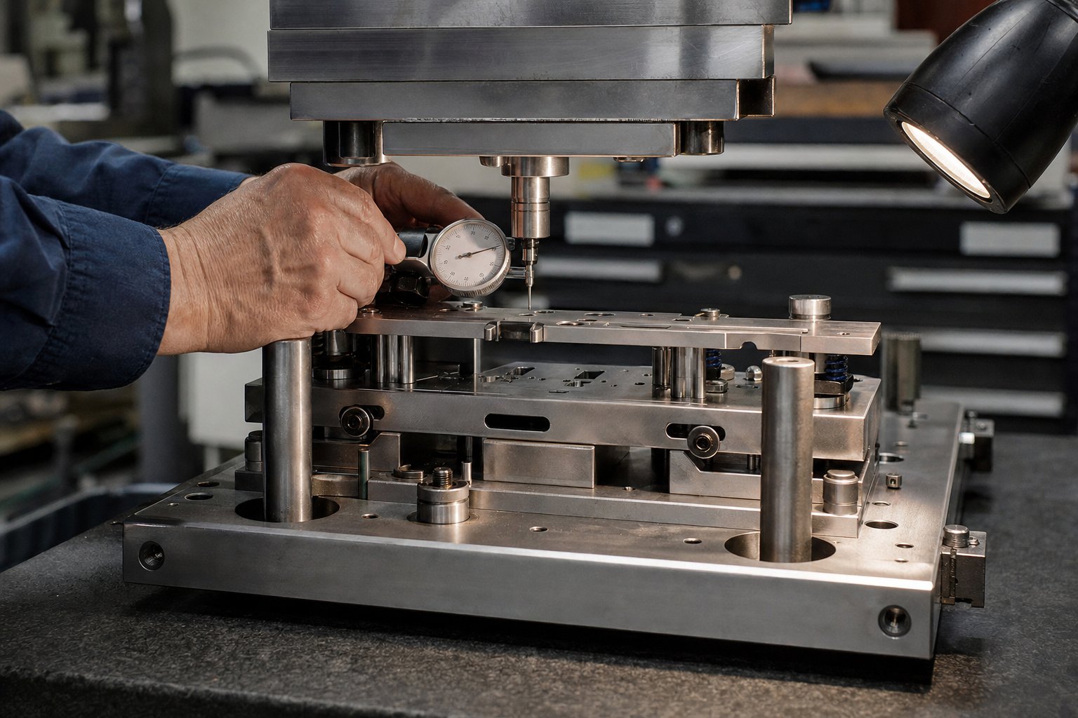
Assemble and Align the Complete Die Set
You now have a collection of hardened, ground, and coated stamping die components sitting on your bench. Each one is dimensionally accurate on its own. The challenge is that individual precision does not guarantee assembled precision. When you bolt twenty or more parts together, every tolerance band stacks, and the cumulative result determines whether your punch edges meet the die openings with the clearance you designed or drift into misalignment that produces scrap on the first hit.
This assembly phase is where experienced metal tool and die professionals separate themselves from shops that simply machine parts. The process demands systematic sequencing, careful measurement at each stage, and techniques that compensate for the reality of tolerance stack-up across multiple components. Even when each individual part is within spec, the combined variation can exceed functional limits if assembly methods do not account for it.
Component Alignment Methods and Tolerance Stack-Up
Imagine five stamping components stacked between the die shoe and die surface, each holding a position tolerance of plus or minus 0.01 mm. In a worst-case scenario, those small variations accumulate to plus or minus 0.05 mm of positional shift at the cutting edge. That is enough to produce uneven burrs, accelerate punch wear on one side, or cause slug pulling.
Controlling this stack-up relies on two primary strategies:
- Match-grinding - Instead of machining each plate independently to an absolute dimension, you grind mating surfaces together or in matched sets. This ensures the interface between two components has near-zero gap regardless of where each part landed within its individual tolerance band. Die sections that share a parting line get ground as a set, guaranteeing coplanarity that independent grinding cannot promise.
- Selective fitting - Measure actual component dimensions after heat treatment and finishing, then pair parts strategically. A punch plate bore that measured slightly toward the high end of tolerance gets paired with a punch shank at the low end, keeping the assembled fit within target clearance. This method trades interchangeability for precision, which is the right trade in dies and stamping applications where performance matters more than part-swapping convenience.
Three structural elements maintain punch-to-die alignment under the dynamic loads of a running press:
- Guide posts and bushings - Precision-ground posts pressed into the lower shoe engage hardened bushings in the upper shoe. Ball-bearing guided post sets hold alignment within 0.005 mm or better, preventing lateral shift even as tonnage climbs. For die and stamping assemblies running at high speed, pre-loaded ball-cage bushings eliminate the play that plain bronze bushings allow.
- Heel blocks - Hardened steel blocks bolted to the die shoe edges absorb the lateral forces generated during cutting and forming operations. Without heel blocks, side-loading from angled cuts or asymmetric strip layouts pushes the upper shoe sideways against the guide posts, accelerating bushing wear and degrading alignment over time.
- Dowel pins - Precision dowels lock each component's position relative to the plate it mounts in. Once a die section is located, two dowel pins fix it against rotation and lateral drift, so removing and reinstalling the section for sharpening returns it to the exact same location every time.
Stripper Design and Spring Pressure Calculations
The stripper plate serves a deceptively critical function in any stamping tool and die assembly. It holds sheet material flat against the die surface during cutting, prevents the strip from lifting with the punches on the return stroke, and guides smaller punches that would otherwise deflect under load. Undersized stripping force causes the material to stick to the punches, producing a violent snap that damages components and creates dimensional variation in your parts. Oversized force wastes press tonnage and accelerates spring fatigue.
Calculating the required stripping force starts with the cutting force itself:
- Cutting force = Perimeter of cut x Material thickness x Shear strength
- Stripping force = 10% to 20% of cutting force
- Design stripping force = Stripping force x 1.3 safety factor (minimum)
For stage tooling and progressive dies that also use the stripper as a clamping surface during forming, double the calculated force for clamping during cutting and triple it for clamping during forming. This ensures the strip cannot shift laterally while work is being done, which is one of the most common sources of dimensional variation in complex progressive tool & die stamping operations.
Spring selection follows from the force requirement:
- Nitrogen gas springs - Deliver two to three times the force of a coil spring in the same footprint. They maintain more consistent force throughout their stroke and are reliable at speeds over 600 strokes per minute. Preferred for production progressive dies where consistent clamping pressure directly impacts part quality.
- Mechanical coil springs - Lower cost and simpler to maintain. Suitable for lower-volume applications and dies where space constraints are minimal. Choose a spring rate that delivers full stripping force within the available deflection travel.
With alignment strategy decided and spring force calculated, the physical assembly follows a specific sequence. Jumping ahead or skipping steps creates problems that cascade through the entire build.
- Inspect and deburr all die shoes, ensuring mounting surfaces are flat within 0.0002 inches and parallel top-to-bottom.
- Press guide posts into the lower shoe (or mount guided post assemblies), verifying perpendicularity to the shoe surface.
- Install heel blocks and secure with socket head cap screws torqued to specification.
- Mount die sections into the lower shoe using dowel pins for location, then bolt down with socket head cap screws. Verify cutting-edge positions relative to guide post centers.
- Install the stripper plate onto the upper shoe with springs at their calculated preload height. Confirm free travel matches the required stripping stroke.
- Mount punches into the punch plate, seating each shank fully against the backup plate. Verify that punch tips extend the correct distance below the stripper face.
- Assemble upper shoe onto guide posts and lower the assembly to check punch entry into die openings. Verify even clearance around all cutting edges using feeler gauges or by examining a light gap.
- Apply final torque to all fasteners in a cross-pattern sequence, re-check critical dimensions, and record the assembled shut height for press setup.
That last dimensional check before the die leaves the bench is your insurance policy. Any misalignment caught here gets corrected in minutes with a shim or a reground surface. The same misalignment discovered during tryout costs hours of press time, disassembly, and rework. With the die set fully assembled and verified on the bench, it is ready for the tryout press where stamped parts reveal whether your design, machining, and assembly decisions actually produce conforming results under real press conditions.
Run Die Tryouts and Debug Until Parts Meet Spec
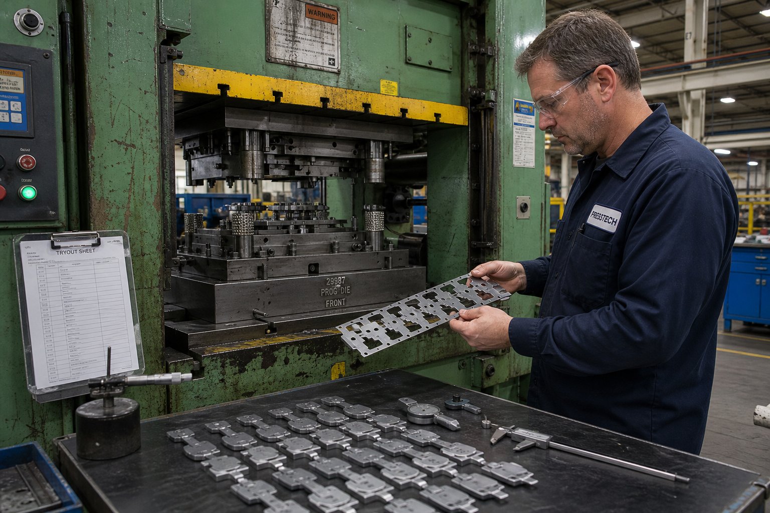
Your die is assembled, inspected on the bench, and measured to print. Everything checks out. So why do most new dies still fail to produce conforming parts on the very first hit? Because a stamping die does not operate in isolation. It operates inside a press, with real material that has property variation, under dynamic loads and speeds that no bench inspection can replicate. The tryout phase is where you discover how your die actually performs under press stamping conditions, and systematically close every gap between design intent and physical reality.
Think of tryout as the final exam for every decision you made during design, material selection, machining, and assembly. The good news: a structured approach to first-hit evaluation and iterative correction gets most dies to spec within a handful of iterations rather than weeks of frustrating guesswork.
Setting Up for First Hits
Die tryout begins with press selection and setup. What is a stamping press in this context? It is a machine that delivers controlled force through a precise linear stroke, closing the die halves together with enough tonnage to cut and form sheet metal. How does a stamping press work during tryout specifically? You set the ram to crawl speed (typically 10-20% of production rate), establish shut height based on the dimension recorded during assembly, and verify that the die sits squarely in the bolster with uniform clamp pressure.
The first hits should always run at reduced speed for three reasons:
- Slower speed gives you time to hear and see problems before they cause damage. A punch hitting a mis-located die section at full speed can shatter tooling. At crawl speed, you feel interference and can stop the press.
- Reduced speed isolates die performance from inertia effects. At production speed, strip dynamics, stripper bounce, and nitrogen spring response all change. Tryout at low speed confirms the die works geometrically before introducing dynamic variables.
- You can safely use soft verification materials. Running lead wire, modeling clay, or soft aluminum shim stock through the die at low speed lets you check shut heights, clearance patterns, and forming depths without risking hardened tool steel.
Feed a short strip of production-grade material (same alloy, same thickness, same temper) through the die for your first sample parts. Never tryout with random scrap stock. Material properties directly affect every aspect of the stamping process, from cutting force and burr formation to springback and draw behavior. Using different material than the production spec guarantees your debugging corrections will be wrong.
First-Hit Inspection and Common Defect Diagnosis
Pull your first sample parts and examine them systematically. Measure burr height with a micrometer or burr gauge. Check feature-to-feature dimensions against the part print. Inspect formed surfaces for splits, wrinkles, and surface marking. Compare left-versus-right and leading-versus-trailing edges for symmetry.
Burr height is your single best indicator of clearance accuracy. A clean-sheared edge with minimal burr (typically under 10% of material thickness) tells you the punch-to-die clearance is correct. Excessive burr on one side of a feature signals uneven clearance, which usually traces back to punch misalignment, die section shift, or press ram tilt rather than incorrect design clearance.
Here is a diagnostic framework for the most common defects you will encounter during precision die stamping tryout:
| Defect | Root Cause | Corrective Action |
|---|---|---|
| Excessive burr (one-sided) | Punch-to-die misalignment; uneven clearance | Re-check guide post alignment; shim punch position; verify die section dowel locations |
| Excessive burr (uniform all around) | Dull cutting edges or insufficient clearance | Sharpen punch and die edges; increase clearance if design was too tight |
| Splits in formed areas | Excessive blank holder force; insufficient material flow; sharp radius | Reduce holding pressure; polish draw radii; increase die entry radius; adjust lubricant |
| Wrinkles in flanges or walls | Insufficient blank holder force; excess material in compression zone | Increase nitrogen spring preload; add or deepen draw beads; modify blank shape |
| Springback (over-bent) | Elastic recovery exceeds compensation; material yield strength higher than nominal | Increase overbend angle; add stiffening bead; increase dwell at bottom of stroke |
| Slug pulling (slugs stick to punch) | Insufficient die-side clearance; vacuum effect; no slug retention features | Add slug retention grooves to die opening; increase clearance slightly; add air blast |
| Hole location out of tolerance | Strip misfeed; pilot pin not engaging; timing error in progressive sequence | Verify feed length; check pilot pin condition and engagement depth; adjust feed release timing |
| Surface scratches or galling | Rough die surfaces; insufficient lubrication; material adhesion to tooling | Polish die surfaces to Ra < 0.2 um; change lubricant type or application; coat die surfaces |
An example of stamping failure diagnosis in practice: you pull a part from a progressive die and notice heavy burr only on the right side of a blanked feature. Your first instinct might be to re-sharpen, but uniform sharpness across the cutting edge rules that out. The real cause is often a 0.01-0.02 mm lateral shift of the punch relative to the die opening. Verifying this with a test cut through soft lead confirms uneven impression depth on opposing sides. The fix is shimming the punch plate or correcting the guide post alignment, not regrinding a still-sharp edge.
Iterative Adjustments and Timing Optimization
No one should expect a new die to run perfectly after a single correction cycle. The stamping process involves too many interacting variables for one-shot perfection. Experienced die makers plan for three to five tryout iterations on a typical production die, and more on complex progressive tools.
Each iteration follows the same loop:
- Run sample parts (minimum 20-30 pieces to see variation, not just a single hit).
- Measure critical dimensions and record results on a data sheet.
- Identify the single largest deviation from spec.
- Diagnose root cause using the defect framework above.
- Implement one correction at a time, then re-run samples to verify the fix worked without introducing new problems.
That last point is critical. Changing multiple variables simultaneously makes it impossible to know what helped and what hurt. This disciplined approach mirrors what stamping experts recommend: understanding how process variables interact and taking a systematic, data-based approach rather than making multiple changes at once and hoping for the best.
Common iterative adjustments during progressive die debugging include:
- Shimming punches - Adding or removing shim stock beneath punch holders to adjust cutting depth and maintain proper die timing after sharpening. As industry practice confirms, always document the exact amount of material removed during grinding and place an equivalent shim under the punch holder. Never exceed three shims before combining into a single replacement shim of the same thickness.
- Adjusting timing in progressive dies - Ensuring that strippers contact the strip before punches engage, and remain in contact until punches fully retract. Pressure-system travel must always exceed work-travel distance to prevent strip lifting and mis-registration between stations.
- Modifying draw beads - Changing bead height, radius, or position to control material flow into draw cavities. Higher beads increase restraining force; lower beads let material flow more freely.
- Tweaking nitrogen spring pressure - Adjusting gas spring preload to change stripping or blank-holding force. Start with calculated values and fine-tune based on actual part quality.
One stamping examples scenario that illustrates the cascade effect: a seemingly simple correction like shimming a punch holder to restore timing after sharpening, if neglected, forces the setup person to lower shut height to achieve a full cut. That lower shut height drives forming stations too deep, generating excessive tonnage that can damage the die or press. The tonnage monitors trip, someone raises the alarm limits, and the die now runs in an abusive condition that shortens its life dramatically. All because one shim was missed.
Two verification techniques help you debug without risking expensive tooling:
- Spot-bluing surfaces - Apply a thin coat of Prussian blue (layout dye) to die or punch surfaces, then close the die on a piece of material or directly (for non-cutting surfaces). The contact pattern revealed by the blue transfer shows exactly where the die is making contact and where gaps exist. Use this to verify forming surface fit, stripper face contact uniformity, and draw pad engagement patterns.
- Soft material impression testing - Run lead wire, modeling clay, or soft aluminum through the die at slow speed. The compressed material reveals shut heights at every station, showing you exactly how much working clearance exists between upper and lower components. This technique is invaluable for verifying that all stations in a progressive die reach proper depth simultaneously without any station bottoming out prematurely or failing to fully form.
High precision metal stamping demands that your tryout results demonstrate not just single-part conformance but consistent repeatability. Run a sequence of fifty or more parts after final corrections and verify that dimensions remain stable without drift. Dimension drift across a short run signals a thermal, wear, or alignment issue that will only worsen at production speed and volume.
The tryout phase ends when your parts consistently meet print dimensions, surface quality passes visual and tactile inspection, and burr heights fall within specification across all cutting stations. At that point, the die is validated for its intended geometry. Transitioning to sustained production, however, introduces a new set of requirements: sensors, speed optimization, documentation, and maintenance planning that keep the die performing at tryout quality over hundreds of thousands of cycles.
Scale From Validated Tooling to Production-Ready Results
A die that passes tryout produces conforming parts at slow speed in short bursts. A production-ready die does the same thing at full cycle rate, shift after shift, while monitoring itself for problems and documenting every quality checkpoint along the way. The gap between those two states is where many teams underestimate the work involved.
Bridging that gap means adding intelligence, speed, and discipline to tooling that already proves geometrically correct. Here is what changes when you move a validated metal stamping die into sustained production.
Sensors, Speed Optimization, and Maintenance Planning
During tryout you watched every stroke. In production, the die runs unattended for hours. Sensors replace your eyes and ears:
- Misfeed detectors - Proximity or photoelectric sensors verify the strip has advanced the correct pitch before the press strokes. A short-feed condition sends a punch into an already-pierced area, damaging tooling instantly.
- Slug sensors - Detect whether slugs are clearing the die opening after each hit. A retained slug stacks under the next blank and can crack a die section or produce a defective part.
- Tonnage monitors - Measure force signatures on each stroke. A gradual increase signals edge dulling; a sudden spike signals a double-hit, misfeed, or foreign material in the die.
- Part-out sensors - Confirm finished metal stamping parts eject cleanly before the next cycle, preventing die crashes on progressive tooling.
With sensors in place, you ramp cycle speed incrementally. Start at 60-70% of target strokes per minute and verify that strip dynamics, stripper timing, and part ejection all behave the same as during tryout. High volume stamping introduces inertia effects that change how the strip lifts, how nitrogen springs respond, and how slugs travel through die openings. Increase speed in 10% increments until you reach the target rate without quality deviation or sensor faults.
Maintenance scheduling locks in the die life gains you designed for. Establish regrind intervals based on tryout data: if burr height reached the reject threshold at 80,000 hits during validation, schedule sharpening at 70,000 as a preventive measure. Document spring replacement intervals, lubrication points, and inspection checkpoints. Structured maintenance programs for press and stamping equipment have been shown to extend tool life by up to 50% and reduce unplanned downtime by 30-45% compared to reactive approaches.
Production Validation and Quality Checkpoints
Industrial metal stamping for regulated industries requires more than parts that look right. You need statistical proof that your process produces conforming sheet metal stamping parts consistently and predictably.
Process capability studies quantify that proof. The Cpk index measures how well your process output centers within the tolerance band. A Cpk value greater than 1.33 is commonly required, corresponding to a defect rate below 64 parts per million. Achieving that number means running a minimum sample size (typically 30-50 consecutive parts from a stable process) and performing dimensional analysis on every critical feature.
For automotive stamping programs, the Production Part Approval Process (PPAP) formalizes these requirements into a structured submission package. PPAP documentation typically includes:
- First-article inspection reports with ballooned drawings
- Process flow diagrams and control plans
- Measurement system analysis (Gage R&R) verifying inspection equipment capability
- Capability studies (Cpk) on critical dimensions
- Material certifications traced to specific coil lots
- FMEA (Failure Mode and Effects Analysis) covering the stamping process
Aerospace programs add their own requirements, often demanding full traceability from raw material heat lot through finished part serialization. The common thread across all regulated industries is that your custom metal stamping die must produce parts within a validated, documented, and repeatable process, not just pass a visual check at the end of a run.
Automotive OEMs and Tier-1 suppliers expect prevention-based quality systems rather than end-of-line sorting. Export-grade automotive stamping dies and the processes built around them typically achieve defect rates in the 50-200 PPM range when operating under proper process controls and maintenance discipline.
When to Partner With an Experienced Die Maker
You now understand the full workflow from part drawing through production validation. Here is the practical reality: most manufacturers benefit from partnering with a specialized die shop for production tooling, particularly for complex progressive dies or high-volume automotive stamping applications where the cost of trial-and-error is measured in six figures.
Building a prototype single-station die in your own shop teaches you the fundamentals. Scaling to a 20-station progressive die running at 400 strokes per minute on an automotive line is a different category of challenge, one that demands specialized equipment, deep process knowledge, and years of iterative experience debugging the kinds of problems this article describes.
The decision to outsource is not a failure. It is an allocation of risk. A dedicated die maker amortizes their investment in simulation software, precision machining centers, tryout presses, and experienced toolmakers across hundreds of projects. You benefit from that concentrated capability without carrying the overhead.
For manufacturers, sourcing managers, and tooling engineers ready to move from understanding the die-making process to requesting quotes on production tooling, YICHEN's stamping die services support the full workflow, from feasibility analysis and CAE simulation through precision machining, trial runs, and final inspection. That end-to-end capability eliminates the coordination risk of splitting work across multiple vendors.
Key criteria for evaluating a die-making partner: in-house CAE simulation and feasibility analysis capability, full CNC machining and wire EDM capacity, dedicated tryout presses for validation before shipment, CMM and optical inspection equipment for dimensional verification, quality system certifications (ISO 9001 minimum, IATF 16949 for automotive programs), and documented maintenance and engineering change support throughout the die's production life.
Whether you build your next stamping die entirely in-house or partner with a specialist for production-grade tooling, the knowledge in this guide gives you the vocabulary, decision frameworks, and technical benchmarks to manage the process with confidence. Every step, from selecting the right die type through heat treatment, assembly, tryout, and production validation, follows a logical chain where informed decisions at each stage compound into a die that hits spec on first tryout and keeps hitting it for the life of the program.
FAQs About Making a Metal Stamping Die
1. How much does it cost to make a metal stamping die?
Metal stamping die costs vary widely based on complexity. Simple single-station dies for prototyping may cost a few thousand dollars, while complex progressive dies for automotive production typically require USD $100,000 to $500,000. Key cost drivers include the number of stations, material selection (D2 vs carbide inserts), tolerance requirements, and whether CAE simulation and multiple tryout iterations are needed. Partnering with an experienced die maker like YICHEN can help control costs through early feasibility analysis and optimized design before committing to machining.
2. What is the best tool steel for stamping dies?
There is no single best tool steel because each die component faces different stresses. D2 (HRC 58-62) is the workhorse for general blanking with excellent abrasion resistance. A2 offers better toughness for forming punches that absorb shock. S7 handles heavy-impact operations on thick stock. M2 retains hardness at high speeds in progressive die stations. Carbide inserts serve ultra-high-volume applications exceeding millions of hits. The right choice depends on your workpiece material, production volume, and acceptable regrind intervals.
3. What is the correct punch-to-die clearance for sheet metal stamping?
Punch-to-die clearance is expressed as a percentage of material thickness per side and varies by sheet metal type. Mild steel requires 8-12% clearance per side, stainless steel needs 10-15% due to work-hardening, and aluminum and brass work best at 5-8%. Running toward the higher end of these ranges reduces tooling strain and extends die life, though it may slightly increase burr height. Always use production-grade material during tryout to validate clearance settings accurately.
4. How many parts can a stamping die produce before it needs maintenance?
Die life between regrinds depends on tool steel grade, workpiece material, and surface coatings. A D2 punch blanking mild steel typically delivers 100,000-150,000 hits before burr height signals regrind. The same punch cutting stainless steel drops to 30,000-50,000 hits. PVD coatings dramatically extend these intervals. TiCN-coated tools stamping high-strength steel have produced over 1.2 million parts versus 50,000 for chrome-plated alternatives. Powder metallurgy tool steels can increase life from 5,000-7,000 cycles to over 40,000 cycles compared to conventional D2.
5. What is the difference between a progressive die and a compound die?
A compound die performs multiple cutting operations (like blanking and piercing) simultaneously in a single press stroke, producing flat parts with tight feature-to-feature tolerances. A progressive die feeds strip material through a sequence of stations, each performing one or two operations, completing a fully formed part with every stroke at high speed. Compound dies suit moderate-to-high volumes of flat parts (50K-500K+ annually), while progressive dies handle complex multi-step parts at high volumes (100K to millions) with bends, forms, and multiple cuts. Progressive dies cost more but deliver lower per-part cost at scale.


