


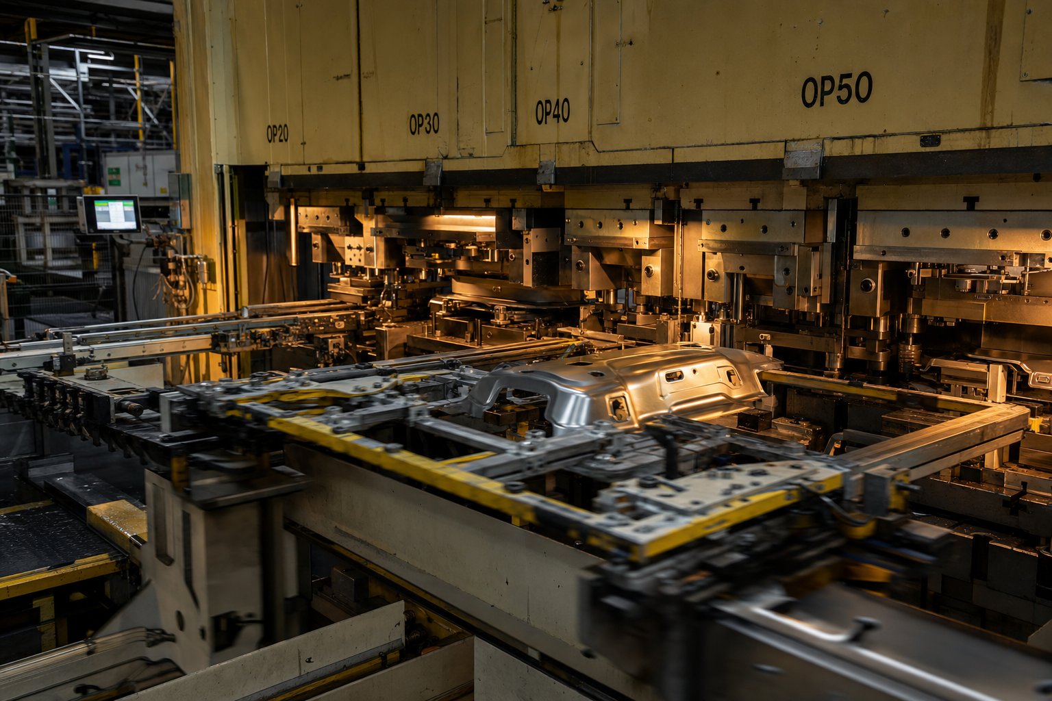
What Is Transfer Die Stamping and Why It Exists
Imagine trying to deep-draw a large automotive oil pan while the workpiece is still tethered to a strip of metal. The carrier strip would buckle, distort, and starve the forming cavity of material. That scenario captures exactly why transfer die stamping exists.
Defining Transfer Die Stamping
Transfer die stamping is a multi-station metal forming process in which a blank is first separated from the raw strip, then moved through a series of independent die stations by a mechanical or robotic transfer system, with each station performing a dedicated forming operation on the free-floating workpiece.
The key phrase here is "separated from the strip." In progressive die stamping, the part stays attached to a carrier strip as it advances through stations. In transfer stamping, the blank becomes a free agent the moment it is cut. A coordinated system of rails, grippers, or fingers picks up that blank and shuttles it from one station to the next with high positional accuracy.
Why Blank Separation Matters
When a workpiece remains connected to its parent material, every forming operation is constrained. Draw depth is limited because material can only flow from the sides still attached to the strip. Large part geometries risk warping the carrier. Multi-axis forming becomes nearly impossible.
Separating the blank removes all of those restrictions. Material can flow freely into the die cavity from every direction, enabling deep draws with uniform wall thickness and complex 3D contours. You gain the freedom to lift, rotate, and reposition the part between stations, which opens up geometries that dies and stamping configurations tied to a strip simply cannot achieve.
Where Transfer Die Stamping Fits in Metal Forming
Transfer die stamping occupies the space between progressive stamping and dedicated single-operation presses. It handles parts that are too large, too deep, or too geometrically complex for a progressive die, yet still need the repeatability and volume throughput of automated press forming. Think fire extinguisher shells, structural automotive pillars, or appliance drums where depth exceeds diameter and tolerances remain tight.
The trade-off is speed. A transfer stamping press typically runs at 15 to 45 strokes per minute compared to 100-plus for a progressive setup. But the geometric freedom and material savings often make that slower cycle the more economical choice overall.
Understanding what a transfer die can and cannot do starts with understanding how the transfer mechanism itself works, because the motion profile of those grippers dictates everything from station layout to press timing.
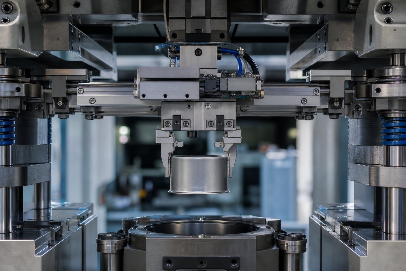
How the Transfer System Physically Moves Parts Between Stations
The transfer mechanism is the heart of any transfer stamping press. It dictates cycle time, part accuracy, and which geometries you can produce. Yet most descriptions of the process gloss over it with a single sentence. Here is what actually happens between the die faces.
Types of Transfer Mechanisms
Transfer systems fall into three categories based on the axes of motion they provide. The right choice depends on part complexity, weight, and target speed.
A two-axis system moves in a single plane, typically lift and advance (X-Z). Two rails running the length of the die rise to lift the part off the lower die, advance it one pitch to the next station, and lower it onto locators. Because the motion is simple, two-axis transfer tooling supports higher stroke rates, but it cannot clamp or orient parts that might shift during travel.
A three-axis system adds a clamping motion. The rails lift, clamp inward onto the part, advance, lower, and release. This three-axis movement in the X-Y-Z planes allows the workpiece to be lifted sufficiently high off the die and placed precisely within perimeter-gauge boundaries at the next station. Three-axis systems are commonly plate-mounted or press-mounted, with finger tooling designed to clear lower-die steels, cams, and guide components on the return path.
Robotic transfer replaces mechanical rails with articulated robots positioned between individual presses in a press-to-press arrangement. Each robot uses vacuum cups or magnetic end-effectors to pick, move, and place parts. Typical cycle times range from 1.5 to 3 seconds per transfer, making robotic systems slower but far more flexible for complex repositioning, part rotation, or turnover between stations.
| Transfer Type | Axes of Motion | Typical Speed (SPM) | Best-Fit Part Complexity |
|---|---|---|---|
| Two-Axis | Lift + Advance | 25 - 45 | Flat or shallow-draw parts with stable geometry |
| Three-Axis | Lift + Advance + Clamp | 15 - 30 | Deep-drawn cups, flanged parts, irregular shapes |
| Robotic | 6-Axis Articulated | 8 - 20 | Large panels, turnover required, multi-press lines |
Gripper and Finger Tooling Design
The grippers, or fingers, are the only components that physically contact the workpiece during die transfer. Their design directly affects part quality and transfer reliability.
In a mechanical three-axis system, fingers are mounted to the transfer rails at each station pitch. They are custom-profiled to match the part geometry at that specific stage of forming. A first-station finger gripping a flat blank looks nothing like a fifth-station finger cradling a deep-drawn cup. Designers must ensure fingers provide enough clamping force to secure the part during high-acceleration moves without marking cosmetic surfaces or deforming thin walls.
Positioning after release is equally critical. Two-axis systems rely on spring pins pressed into the lower die to hold orientation until the die closes. Three-axis transfer press tooling uses a combination of part geometry, nesting blocks, and locator pins to maintain location once fingers retract. For robotic systems, vacuum cups or magnets grip the part, requiring the workpiece to float at least 1 mm above the lower die to prevent magnetic force leakage into the die steel.
Pitch length matters too. Longer pitch distances force higher accelerations during the transfer stroke, which can create vibration and unstable part movement, especially with thin-gauge material that lacks stiffness. Heavier workpieces demand stronger rails and fingers with greater mass, increasing inertia loads and often requiring reduced operating speed.
Synchronizing Transfer Motion with Press Stroke
Every transfer motion must complete within the window when the press is open. Picture the timing sequence: the ram reaches top dead center and the die opens. Part lifters raise the workpiece off the lower die surface. The transfer rails close inward, grippers engage the part edges, and the rails lift the blank clear of all die components. The assembly advances one pitch horizontally, lowers the part onto the next station's locators, releases, and retracts to the start position, all before the ram begins its downward working stroke.
This choreography is governed by rotary cam switches or electronic cam profiles that issue signals at precise crank-angle positions. A typical transfer stamping press uses three or more cam signals: press-in-operation, press-at-home-position, and unloader-command. If the transfer cycle cannot complete within the available open time, the press speed must slow down. In practice, transfer time, not forming force, is the factor that caps production rate.
Transfer-motion simulation software helps engineers design motion profiles that balance inertia, vibration, and speed. By optimizing acceleration curves, you can push cycle rates higher without sacrificing positional accuracy or risking part instability during transit.
With the mechanics of part movement understood, the next question becomes what actually happens to the blank at each station it visits, from the initial draw through final ejection.
Step-by-Step Process from Blank Creation to Finished Part
A raw coil of steel enters one end of the press. A finished, dimensionally accurate part exits the other. Between those two points, a tightly choreographed sequence of operations transforms flat sheet into complex three-dimensional geometry, one station at a time. Here is exactly what happens at each stage.
Blank Creation and Strip Processing
Everything starts with a coil, sometimes weighing several tons, mounted on an uncoiler. The strip feeds through a straightener that removes coil set (the curvature memory from being wound) and delivers flat stock to the press. Consistent flatness matters because any residual bow or edge wave will propagate into the blank and compromise forming accuracy downstream.
At the first station inside the press, a blanking die shears the workpiece free from the strip. This is the defining moment of the transfer die stamping process: the part loses its physical connection to the parent material and becomes a free-floating blank. Blank shape is not always a simple circle or rectangle. Engineers often design developed blanks with optimized contours, sometimes scalloped or notched, to control material flow during subsequent draws and minimize trimming waste later.
In some production setups, blanks are produced offline on a separate blanking press, stacked, and then fed into the transfer press through an automated de-stacker. This approach decouples blanking speed from forming speed, which is useful when the blanking operation is faster than the transfer cycle or when multiple blank shapes feed into the same press.
Multi-Station Forming Sequence
Once the blank is created, the transfer mechanism grips it and begins shuttling it through a series of independent die stations. Each station holds its own tooling, performing one or two dedicated operations on the free-floating workpiece. The sequence is designed to shape the part incrementally, never exceeding the material's formability limits in a single hit.
Here is the typical station-by-station progression for a precision die stamping operation:
- Drawing - The blank is forced into a die cavity by a punch, forming the initial cup or shell shape. A blank holder controls material flow and prevents wrinkling at the flange. This station establishes the primary geometry.
- Re-drawing - When the required depth exceeds what a single draw can achieve (generally beyond a 1.5:1 to 2:1 draw ratio), one or more re-draw stations reduce the diameter while increasing depth. Each re-draw progressively deepens the shell without thinning walls beyond acceptable limits.
- Trimming - Excess flange material left from the drawing operation is sheared away. Trim stations produce a clean, dimensionally accurate perimeter. The scrap drops through the die and is conveyed out of the press.
- Piercing - Punches create holes, slots, or other internal features. Piercing is positioned after drawing because holes punched into a flat blank would distort during subsequent forming. Placing it here preserves hole location accuracy.
- Flanging - Edges are bent or rolled to create lips, mounting flanges, or stiffening ribs. Flanging stations use form punches or cam-driven slides to bend material at angles relative to the press stroke direction.
- Coining or Restriking - High-tonnage compression refines critical dimensions, sharpens radii, flattens surfaces, or imprints details. Coining achieves tolerances tighter than standard forming because the material is plastically deformed against rigid die surfaces under extreme pressure.
The number of stations varies based on part complexity. A simple drawn shell might require four or five stations. A complex automotive structural component with multiple hole patterns, flanges at different angles, and tight dimensional callouts could use ten or more. Unlike the progressive die stamping process, where the strip dictates station spacing, transfer die layouts space stations to accommodate the largest part profile at each stage plus clearance for finger tooling.
What makes this sequence powerful is that each station's die and stamping tooling can be optimized independently. A draw station focuses entirely on material flow. A trim station focuses entirely on clean shearing. There is no compromise forced by having the part tethered to neighboring stations through a carrier strip.
Final Operations and Part Ejection
The last stations in the sequence handle finishing work and secondary operations that would otherwise require separate machines and additional handling. This is where transfer die stamping delivers a capability gap that few engineers fully exploit.
In-die secondary operations can include:
- Tapping heads that cut threads directly into pierced holes
- Projection welding units that attach nuts, brackets, or studs
- Automated feeders that insert bushings, seals, or sub-components
- Marking or engraving stations for part identification
Integrating these operations eliminates downstream handling, reduces work-in-progress inventory, and removes the quality risk that comes with transferring parts between separate manufacturing cells. A part that would traditionally require stamping, then transport to a tapping station, then transport to a welding cell, instead exits the press fully finished.
After the final forming or assembly station, the transfer mechanism moves the completed part to an ejection position. From there, a conveyor, stacking mechanism, or robotic pick-and-place system removes the part from the press. Parts may be stacked directly into shipping containers or placed onto inspection conveyors for in-line quality verification.
The entire cycle, from coil feed to final ejection, repeats every 2 to 4 seconds depending on press speed and transfer complexity. Each stroke produces one finished part, and the cadence continues uninterrupted across production runs that can span hundreds of thousands of pieces.
Of course, achieving this level of throughput depends heavily on matching the press itself to the demands of the forming sequence. Tonnage, bed size, stroke length, and cushion systems all need to align with the part geometry and material being formed.
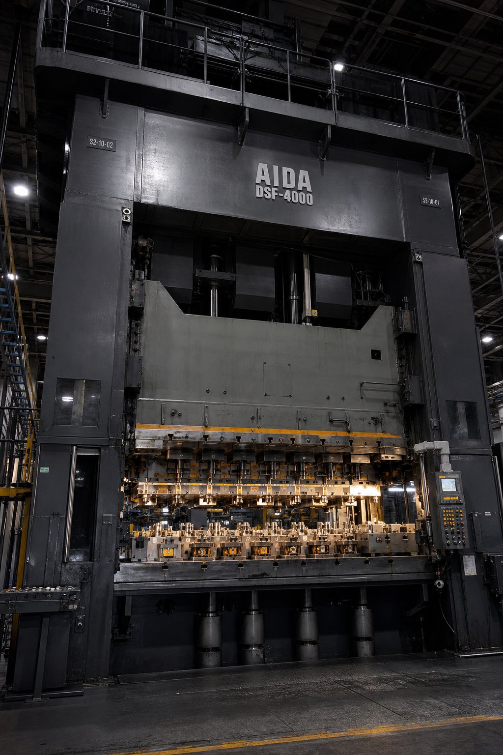
Press Requirements and Material Specifications for Transfer Die Stamping
A forming sequence only performs as well as the press behind it. You can design the perfect station layout, but if the die stamping press lacks tonnage for deep draws, stroke for part clearance, or bed area for rail clearance, the process stalls before the first blank hits a cavity. Specifying the right press is one of the most consequential decisions in any transfer press stamping project, and it is also one of the most commonly under-engineered.
Tonnage and Bed Size Requirements
Transfer die stamping generally demands higher tonnage than a comparable progressive stamping press running similarly sized features. The reason is straightforward: blanks are larger, draws are deeper, and each station's forming load stacks up against the same slide. A progressive die press might handle a family of small features at 200 to 400 tons. A transfer press forming a deep-drawn shell from a thick blank routinely operates in the 600 to 2,000 ton range, with large automotive structural parts pushing into the 2,500 to 3,000 ton territory.
Bed size is equally critical and often overlooked. The bolster must accommodate all independent die stations arranged in sequence, plus clearance on both sides for the transfer rails. A through-the-window transfer system positions rails inside the press window but outside the bolster, consuming window width that could otherwise carry wider coil. Front-and-rear systems keep rails entirely outside the press, allowing the full window width for blanks and tooling. In either case, engineers must account for finger tooling sweep radius, clamp stroke, and the return path clearance between fingers and lower die components when sizing the bed.
As parts grow more complex and OEMs push for fewer components per assembly, expect more stations per die set. That trend points toward larger bolsters and side-by-side multiple-press systems that can operate individually or synchronize into a single long transfer line when extra stations are needed.
Stroke Length and Speed Considerations
Many engineers spec stroke length based solely on forming depth. That is a mistake. The press stroke must also provide enough crank angle for the transfer mechanism to complete its full motion cycle while the die is open. A proven guideline from transfer press specialists is a 4:1 ratio: if a part requires 6 inches of working stroke, specify a press with at least a 24-inch total stroke. That extra travel buys the degrees of crank rotation the transfer needs to lift, advance, lower, and retract without rushing the motion profile.
Speed is where transfer press stamping diverges most sharply from progressive die work. A progressive die press commonly runs 40 to 100-plus strokes per minute because the strip advances a fixed pitch with minimal mechanical complexity. A transfer press typically runs 10 to 30 SPM. The limiting factor is not forming force or material behavior. It is transfer time. The press must hold open until grippers complete their full cycle. With link-motion press drives, the available transfer window shrinks even further because the ram dwells at top dead center for fewer crank degrees than a standard eccentric drive.
Servo-driven presses offer a workaround. Programmable slide motion can dwell at top dead center, giving the transfer system additional milliseconds to complete its movement without reducing overall cycle rate. This flexibility makes servo presses increasingly popular for transfer applications where cycle time is a competitive differentiator.
Cushion Systems and Precision Requirements
Deep-draw stations inside a transfer die rely on hydraulic or nitrogen cushion systems built into the press bolster. These cushions act as blank holders during the draw stroke, applying controlled pressure to the flange of the blank to regulate material flow into the die cavity. Without adequate cushion tonnage, wrinkles form. With too much pressure, the material tears.
Multi-point cushion control is standard on modern transfer presses. Rather than a single uniform force, individual cylinders beneath the die apply different pressures at different locations across the blank. This compensates for asymmetric part geometries where material flow rates vary from one side to another.
Bottom-dead-center (BDC) accuracy is another specification that separates a capable transfer press from an inadequate one. Because each station performs forming to tight tolerances, any variation in ram position at BDC translates directly into dimensional variation on the part. Consistent BDC within plus or minus 0.025 mm is typical for quality transfer work. Thermal expansion of the press frame during long production runs can drift BDC, so hydraulic overload systems and automatic shut-height compensation are standard safeguards.
| Specification | Transfer Die Stamping Press | Progressive Die Press |
|---|---|---|
| Tonnage Range | 600 - 3,000 tons | 100 - 800 tons |
| Typical Speed (SPM) | 10 - 30 | 40 - 100+ |
| Bed Area | 3,000 x 1,500 mm and larger | 1,500 x 800 mm typical |
| Stroke Length | 300 - 600 mm (4:1 rule applied) | 50 - 200 mm |
| Material Thickness | 1.0 - 6.0 mm common | 0.2 - 3.0 mm common |
| Cushion System | Multi-point hydraulic, high tonnage | Single-point or spring-based |
| BDC Accuracy | ± 0.025 mm | ± 0.05 mm |
Material selection ties directly back to press capacity. Transfer die stamping handles thicker gauges, typically 1.0 mm to 6.0 mm, because the free-floating blank and independent station design accommodate the higher forming forces thick stock demands. Mild steel, high-strength low-alloy (HSLA) steel, and stainless steel are the most common substrates. Aluminum alloys in the 5000 and 6000 series work well for deep draws but require careful cushion tuning due to lower ductility margins. Copper and brass see use in electrical housings and heat exchangers where conductivity matters, though their higher material cost pushes engineers toward progressive tooling for smaller copper or brass parts.
Softer tempers, such as annealed or half-hard conditions, suit deep-draw transfer work because they allow greater plastic deformation before fracture. Harder tempers reduce formability and increase springback, often requiring additional restriking stations to hit final dimensions. Matching material temper to the forming sequence early in design prevents costly station additions after die build.
With press and material parameters locked down, the real engineering challenge shifts to part geometry itself: what shapes can you form, how deep can you draw, and what spacing rules keep features intact through the entire station sequence.
Design Rules and Geometric Constraints for Transfer Die Parts
Knowing what the press can deliver is half the equation. The other half is knowing what your part geometry demands, and whether it stays within the formability envelope at every station. The design rules below give engineers concrete thresholds to evaluate early, before tooling steel gets cut and before station counts spiral beyond budget.
Draw Ratios and Depth Limits
Draw ratio, the relationship between blank diameter and punch diameter, is the single most critical number in any deep-draw transfer die design. Exceed the material's limit and the cup fractures at the punch radius. Stay well inside it and you waste stations on unnecessary conservatism.
For a single draw operation, maximum draw ratios depend heavily on the substrate. Published DFM guidelines provide these limits under optimal lubrication and blank holder force:
| Material | Max Draw Ratio (Single Draw) | Max Draw Ratio (With Redraws) |
|---|---|---|
| CRS DC04 (Deep Draw Steel) | 2.0:1 | 3.5:1 |
| Stainless 304 | 1.8:1 | 3.0:1 |
| Aluminum 5052-O | 1.8:1 | 3.2:1 |
| Copper C11000 | 2.1:1 | 4.0:1 |
| Brass C26000 | 2.0:1 | 3.5:1 |
When draw depth exceeds roughly 1.5 times the punch diameter, plan for at least one re-draw station. Each subsequent reduction should not exceed 20-25% of the previous shell diameter for draw-quality steel. Thinner gauges and harder tempers reduce those percentages further. As deep-draw design principles emphasize, all material needed for the final part shape must be present in the first draw, so blank sizing is committed up front and cannot change after that initial station.
Wall thinning during drawing follows a predictable pattern. The mid-wall stretches 5-15% thinner than the original blank. The bottom corner at the punch radius thins up to 20%, making it the critical failure zone. Meanwhile, the flange area thickens 10-20% from circumferential compression. Specify a minimum wall thickness on drawings rather than a nominal to reflect how drawn parts actually behave.
Feature Spacing and Web Width Rules
Holes, slots, and cutouts cannot go just anywhere on a transfer-die part. Features placed too close to edges or to each other compromise the web of material that holds everything together, especially during the high-acceleration transfer moves between stations where grippers exert clamping force on the part walls.
Here are the spacing rules engineers should apply:
- Hole-to-edge distance: Minimum 2.0 times material thickness for stock up to 3.0 mm; increase to 2.5t for thicker gauges. Rectangular features need 2.5t to 3.0t due to higher stress concentration at corners.
- Hole-to-hole spacing: Minimum center-to-center distance of 2.0 times material thickness with standard tooling; 1.5t with precision-guided punches. Closer spacing risks web collapse during piercing.
- Hole-to-bend distance: At least 2.0t plus the inside bend radius (2.0t + R) for mild steel; increase to 2.5t + R for stainless. Holes closer than this distort, ovalize, or develop edge cracks during flanging.
- Minimum hole diameter: 1.0 times material thickness with standard tooling. Below that threshold, punch life drops 3-5x and guidance requirements increase substantially.
- Minimum flange length: 4 times material thickness. Shorter flanges cannot be reliably formed without special cam tooling.
- Gripper contact zones: Maintain at least 5 mm of flat, unformed surface at part edges where transfer fingers will grip. Features in the grip zone create handling instability and surface marking.
These values apply broadly across the types of stamping dies used in transfer work. Keep in mind that progressive stamping materials like thin-gauge brass or copper strip often use tighter spacing rules because the carrier strip provides structural support that a free-floating blank lacks. In copper progressive stamping or brass progressive stamping, parts remain tethered, so web integrity during transfer is not a concern. Transfer die parts must be self-supporting at every stage, which makes conservative feature spacing non-negotiable.
How Geometry Drives Station Count
Every geometric feature on your part maps to at least one station in the die. Understanding that relationship lets you estimate tooling cost and press size before detailed die design even begins.
A few rules of thumb for die stamping support for large parts:
- Each draw reduction adds one station. A part with a 3.5:1 final draw ratio in DC04 steel needs the initial draw plus two re-draw stations at minimum.
- Piercing after forming adds one station per hole pattern group. Holes at different orientations or elevations may require separate stations or cam-driven units.
- Each unique bend angle or flange direction adds one station unless multiple flanges can be formed simultaneously by a compound slide.
- Trimming typically requires one station, though complex trim lines split across two hits reduce cutting force and improve edge quality.
- Coining or restriking for tight tolerances adds one station. Any dimension held below ±0.08 mm on a formed surface likely needs a dedicated restrike.
A simple drawn cup with a trimmed flange and four pierced holes might need five stations. A structural automotive bracket with two draw reductions, asymmetric flanges, multiple hole patterns at different elevations, and a coin station could require ten or more. In steel progressive stamping, many of these operations happen on the same strip with minimal pitch, but the geometry constraints of a carrier strip cap draw depth and part size, pushing complex and large parts squarely into transfer territory.
These geometric rules establish whether a part belongs in a transfer die. The next step is understanding how transfer die stamping compares head-to-head with progressive stamping across the full range of decision factors, from volume and speed to cost and complexity.
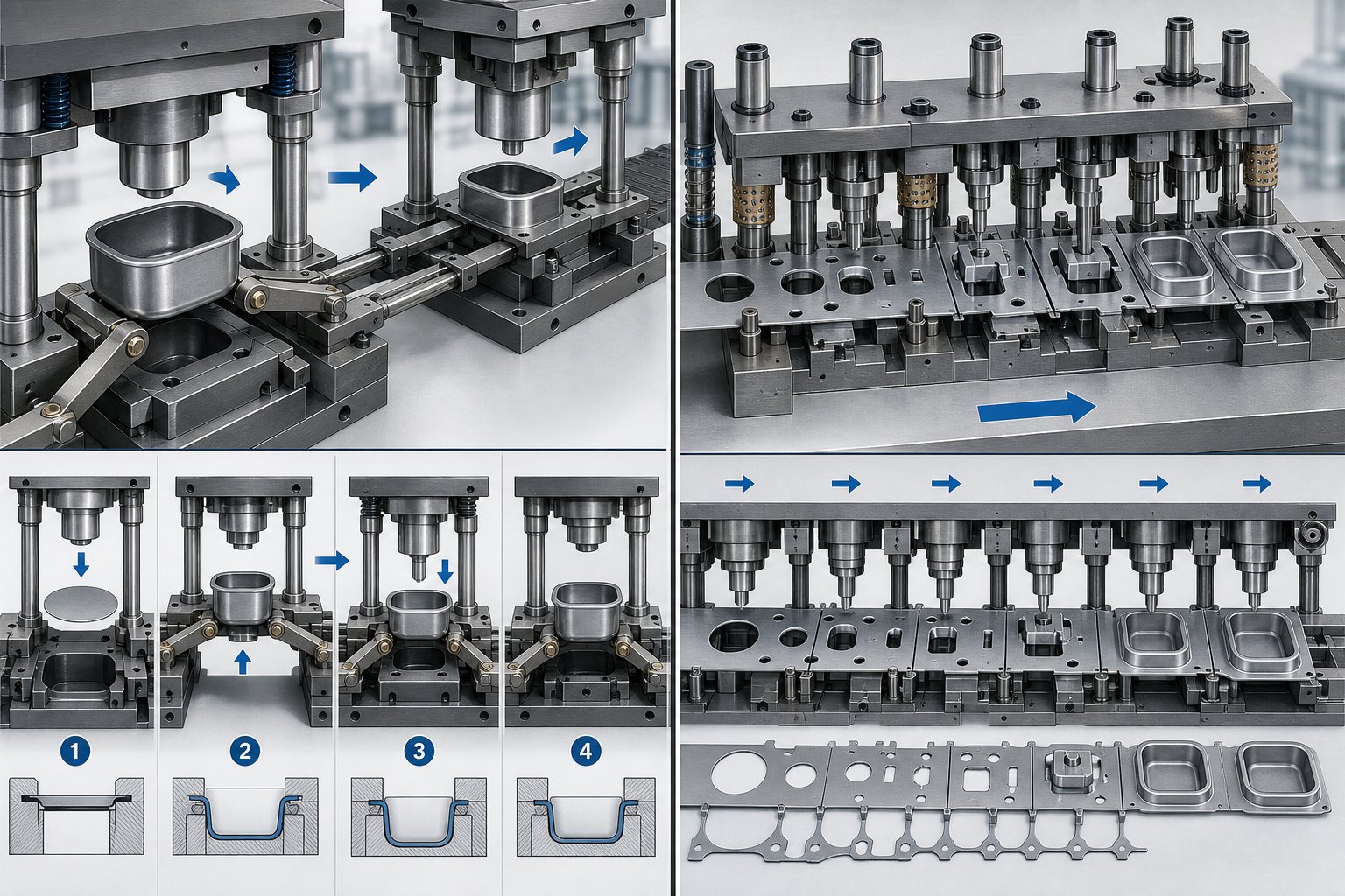
Transfer Die vs Progressive Die Stamping
Geometric design rules tell you whether a part can be formed in a transfer die. But the more common question engineers face is not "can it be formed" but "should it be formed in a transfer die or a progressive die?" The answer depends on how geometry, volume, speed, and cost interact for your specific part. Here is a comparison that moves past the generalities and into the decision logic that actually drives tooling strategy.
Geometry and Size Constraints Compared
What is a progressive die? It is a single die block containing multiple integrated stations through which a continuous strip of metal advances one pitch per press stroke, with every feature added sequentially while the part remains attached to a carrier strip. That carrier strip is both the strength and the limitation of progressive die stamping. It provides a built-in transport mechanism, which is why progressive stamping delivers extreme speed. But it also constrains every forming operation to what the attached web can tolerate without buckling, tearing, or distorting adjacent stations.
Transfer die stamping removes that constraint entirely. Because the blank is free-floating, each station can apply forming force from any direction, at any depth, without worrying about how that force propagates through a carrier strip into neighboring parts. This distinction creates a clear geometry divide:
- Draw depth: Progressive dies typically limit draw depth to 1.0-1.5 times the punch diameter before the strip becomes unstable. Transfer dies routinely achieve 3.5:1 or deeper with re-draw stations.
- Part size: Progressive metal stamping works best for parts that fit within a strip width of roughly 25 mm to 500 mm. Transfer dies handle blanks from 150 mm up to 1,500 mm or larger.
- Multi-axis forming: Progressive dies form primarily in the press stroke direction. Transfer dies allow rotation, flipping, and cam-driven side actions at every station because nothing connects the part to the strip.
- Feature access: Progressive stamping die designs must keep all features accessible from above or below relative to the strip plane. Transfer setups can form features on all sides of the workpiece, including undercuts that would be impossible with a tethered blank.
A practical rule from experienced tooling engineers: if the part can be economically nested in strip form and does not exceed moderate draw depths, progressive dies usually win. If the part demands full 360-degree forming freedom, deep cups, or a footprint that cannot fit a strip layout efficiently, transfer is the viable route.
Speed and Volume Tradeoffs
Production speed is where progressive stamping holds its clearest advantage. A progressive stamping process runs continuously because the strip feeds automatically with every press stroke. There is no mechanical transfer to wait for, no gripper engagement, no lift-and-advance cycle consuming crank angle. The result is stroke rates of 40 to 100-plus SPM for typical progressive dies, with high-speed progressive configurations pushing beyond 200 SPM for small connector parts.
Transfer die stamping operates in the 10 to 30 SPM range for most applications. The bottleneck is not forming force but transfer time: the press must hold open until grippers complete their full motion cycle. Even with servo-driven presses that dwell at top dead center, the mechanical reality of moving a free-floating part through space limits how fast the system can cycle.
That speed gap narrows as parts grow larger. A progressive die running a large bracket at 300 mm strip width might achieve only 30-40 SPM because the feed length per stroke is substantial and the tonnage demands slow the press. A transfer die running the same part at 20-25 SPM with deeper forming capability might actually produce more usable parts per hour once you account for the secondary operations the progressive version would need downstream.
Volume thresholds also factor in. Progressive stamping dies justify their higher upfront engineering complexity when annual volumes reach 500,000 pieces or more. Transfer dies make economic sense at lower volumes, sometimes as low as 50,000 to 100,000 annually, because their tooling is modular and individual stations cost less to modify when design changes arise.
Cost and Tooling Investment Differences
Tooling cost is not a simple "one is cheaper" comparison. The cost structure differs fundamentally between the two approaches.
Progressive dies concentrate all operations into a single integrated die block. This makes the tool itself complex to design and build, requiring tight alignment across all stations, intricate strip layouts, and precision piloting. Initial tooling cost for a progressive stamping die is typically higher because any error in one station can compromise the entire tool. However, once built and validated, the per-part cost drops dramatically at scale because cycle times are fast and labor content per piece is minimal.
Transfer dies use separate, independent die sets at each station. Each station's tooling is simpler in isolation, but the total investment includes multiple die sets plus the transfer mechanism and finger tooling. The combined cost often exceeds a progressive die for equivalent part complexity. The trade-off is flexibility: if one station needs modification, you change only that station without touching the rest. Engineering changes after production starts cost less in a transfer setup because the modularity contains the impact.
Material utilization is another cost lever. Progressive dies generate a carrier strip skeleton that becomes scrap after parts are cut free. Depending on part geometry, skeleton waste can consume 30-50% of incoming material. Transfer dies blank the workpiece with optimized contours that can nest tightly on the strip, often achieving 75-85% material utilization for round or near-round parts. When material cost dominates (stainless steel, nickel alloys, thick gauge stock), that utilization advantage can offset the higher tooling investment.
| Decision Factor | Transfer Die Stamping | Progressive Die Stamping |
|---|---|---|
| Part Size Range | 150 mm to 1,500+ mm | 25 mm to 500 mm typical |
| Draw Depth Capability | Up to 3.5:1 or deeper (with redraws) | Limited to 1.0-1.5:1 by carrier strip |
| Production Speed (SPM) | 10 - 30 | 40 - 100+ (200+ for small parts) |
| Tooling Cost (Relative) | Higher total; modular and easier to modify | High upfront; expensive to change once built |
| Material Utilization | 75 - 85% typical for optimized blanks | 50 - 70% (carrier strip becomes scrap) |
| Geometric Complexity | Deep draws, multi-axis, large 3D forms | Moderate draws, primarily planar features |
| Best Volume Range | 50,000 - 500,000+ annually | 500,000 - millions annually |
| Design Change Flexibility | Individual stations modified independently | Changes often require full die rework |
The middle ground exists for parts that could technically work in either process. A moderately deep bracket with standard hole patterns and simple flanges might stamp progressively or in a transfer die. When both are feasible, the tipping factors are annual volume (high volume favors progressive), material cost sensitivity (expensive alloys favor transfer for better utilization), and anticipated design changes (unstable designs favor transfer modularity). A capable stamping engineering team evaluates the print, material, volume, and downstream assembly requirements before recommending one path over the other.
This comparison clarifies which process suits a given part. But choosing the right process is only the beginning. Validating that the chosen transfer die design will actually produce conforming parts, without expensive trial-and-error iterations on hardened tool steel, requires a different set of engineering tools: simulation and prototyping.
Simulation and Prototyping in Transfer Die Design
Choosing the right process and setting geometric constraints on paper is one thing. Proving those choices will produce conforming parts before committing six figures to hardened tool steel is something else entirely. This is where simulation and prototyping bridge the gap between design intent and production reality.
Forming Simulation and FEA Validation
Finite element analysis lets engineers watch material flow digitally, station by station, before any metal gets cut. The software predicts exactly where thinning will approach failure limits, where wrinkles will form under insufficient blank holder pressure, and how much springback the part will exhibit once the press opens.
The workflow follows a logical sequence:
- Import CAD geometry for each station's punch, die, and blank holder surfaces.
- Define material properties including yield strength, work-hardening curves, anisotropy coefficients, and friction values for the specific alloy and lubrication being used.
- Simulate each station sequentially, carrying the stress and strain state from one operation forward as the input condition for the next. This sequential chaining is critical because residual stresses from drawing affect trimming behavior, which in turn affects flanging accuracy.
- Analyze results against forming limit diagrams (FLDs), dimensional targets, and wall-thinning specifications.
Forming simulation platforms designed for stamping processes, like those described by Keysight, provide a virtual press-line environment where any transfer die process can be defined, tested, and optimized long before physical tools are produced. This approach detects defects such as splits, excessive thinning, and dimensional deviation at the concept stage, when changes cost hours of engineering time rather than weeks of die rework. Unlike progressive die tooling where strip continuity adds simulation complexity, transfer die simulation treats each station as an independent forming event on a free blank, making sequential analysis more straightforward.
Physical Prototyping Approaches
Simulation catches the majority of forming issues, but physical validation still matters for confirming surface quality, verifying material behavior at the margins, and building confidence before full production investment. Engineers have several prototyping paths depending on budget and timeline:
- Soft tooling tryouts: Kirksite (zinc alloy) or mild steel dies machined to near-production geometry. These tools survive hundreds to low thousands of hits, enough to validate draw depth, material flow, and overall formability without the lead time or cost of hardened progressive tool and die sets.
- 3D-printed die inserts: Research validated by Asnafi et al. (2019) demonstrated that 3D-printed maraging steel inserts produced via laser-based powder bed fusion survived 50,000 forming strokes and 100,000 trimming strokes on 2 mm DP600 steel with approved surface quality. For form validation and short-run production, 3D-printed inserts cut lead time roughly in half compared to conventional toolmaking while matching performance.
- Incremental forming: For very low volumes or early proof-of-concept work, CNC incremental sheet forming produces representative part geometry without dedicated dies. It cannot replicate production strain paths exactly, but it confirms whether the basic shape is achievable in the chosen material.
Each approach serves a different stage of readiness. Soft tooling confirms the forming sequence works. 3D-printed inserts validate wear behavior and surface finish at near-production conditions. Incremental forming answers the fundamental question of whether the geometry is feasible at all.
Reducing Engineering Changes Through Upfront Analysis
Engineering changes after die build are expensive. A single station modification on hardened tool steel can cost $15,000 to $50,000 and add weeks to a project timeline. Multiply that across several stations in a transfer die, and late-stage changes threaten project viability.
Simulation compresses that risk into the design phase where iterations are cheap. Industry experience confirms that identifying stress concentrations, thermal problems, and fatigue points in the virtual phase enables smoother transitions to manufacturing and limits disruptions downstream. For transfer die stamping specifically, sequential station simulation catches problems like insufficient material in re-draw stages or springback accumulation across multiple hits, issues that only emerge when the full forming sequence runs in order.
Experienced transfer die stampings suppliers understand this validation cycle and build it into their project timelines. YICHEN, for example, supports feasibility analysis and process validation for multi-station forming, helping manufacturing engineers evaluate whether transfer stamping is viable for their specific part geometry before committing to full tooling investment. Their approach to transfer stamping die design emphasizes stable repeatability from simulation through production, which means fewer surprises during physical tryout and a shorter path from concept to validated tool.
For engineers evaluating progressive die metal stamping services versus transfer die approaches, simulation provides objective data to support the decision. Run both configurations digitally, compare material utilization, station count, and predicted defect risk, and let the results guide the tooling investment rather than intuition alone.
Simulation and prototyping de-risk the tooling build. But even a perfectly validated die eventually wears. Understanding how transfer dies degrade over time, and how to manage that degradation proactively, determines whether a tool delivers consistent parts for 200,000 strokes or two million.
Limitations and When NOT to Use Transfer Die Stamping
Simulation can confirm a part will form correctly. It cannot tell you whether transfer die stamping is the most economical way to produce it. Every process has boundaries, and engineers who understand where this one falls short make better tooling investments than those who default to it because the geometry fits.
Production Speed and Volume Limitations
The most tangible limitation is speed. Transfer die stamping typically runs at 10 to 30 strokes per minute. A high speed progressive die stamping setup producing small connectors or brackets operates at 40 to 100-plus SPM, with some configurations exceeding 200 SPM. That gap is not a tuning issue. It is structural. The press must hold open while grippers lift, advance, lower, and retract. No amount of optimization eliminates the physics of moving a free-floating blank through space.
For parts where annual demand exceeds one million pieces and the geometry stays within progressive die limits, the speed penalty makes transfer stamping the wrong choice. You are paying for geometric freedom you do not need while leaving cycle time on the table.
Beyond speed, the broader cost structure stacks up differently than many engineers expect. Transfer presses consume more floor space due to larger bed areas and rail clearance. Controls are more sophisticated because transfer motion must synchronize precisely with press stroke. Maintenance demands increase because you are managing both forming dies and a mechanical transfer system with its own wear items: rails, fingers, cam mechanisms, and servo drives.
When Progressive or Compound Dies Are Better
Not every stamped part needs the forming freedom a transfer die provides. Several common scenarios clearly favor alternative tooling:
- Small flat parts with simple blanking and piercing: A compound die produces these in a single stroke with excellent flatness and concentricity. Compound die stamping eliminates the need for multiple stations entirely, reducing both tooling cost and cycle time for washers, shims, laminations, and similar planar geometries.
- High-volume parts with moderate draw depths: If the part fits on a carrier strip and draw depth stays below 1.5:1, progressive stamping and fabrication delivers lower per-piece cost at volumes above 500,000 annually. The progressive tool handles forming, piercing, and cutoff in one integrated die without transfer mechanisms.
- Parts requiring extremely tight flatness: A compound die applies blanking and forming forces symmetrically in a single hit, producing flatter parts than multi-station transfer where cumulative handling introduces slight distortions.
- Very low annual volumes (under 10,000 pieces): CNC machining, laser cutting with press brake forming, or hydroforming may produce parts more economically because they avoid dedicated die investment entirely.
- Simple symmetric shapes with no secondary features: Deep-drawn cups with no holes, no flanges, and no tight tolerances can run on single-action draw presses with manual loading at a fraction of transfer tooling cost.
The common thread across these scenarios is that the part geometry does not demand multi-axis forming freedom on a free-floating blank. When progressive die stamping services can deliver the required features within strip-based constraints, that route almost always wins on cost per piece at scale.
Setup Time and Changeover Considerations
Transfer die changeovers take longer than progressive die changeovers. Where a progressive tool change might take 30 to 90 minutes on a well-organized press, a transfer die changeover involves swapping multiple independent die stations, re-aligning transfer rails, changing finger tooling at every pitch, and re-synchronizing the transfer motion profile with the new station layout. Total changeover times of 2 to 4 hours are common. Complex multi-station setups can stretch beyond a full shift.
Several factors drive that duration. Each station's die must be individually bolted, shimmed, and aligned. Transfer fingers must be changed to match new part geometry at each forming stage. Rail pitch may need adjustment if the new job uses different station spacing. SMED methodology helps by separating internal and external setup activities: staging next-job dies, pre-assembling finger tooling on a spare rail set, and pre-loading press parameters all happen while the current job runs.
Strategies that reduce changeover impact include standardized die heights across all station tooling to eliminate shut-height adjustments, quick-change clamping systems that replace bolted connections, and programmable press controls that store complete parameter sets for each part number. Manufacturers running frequent changeovers should also consider dedicating presses to product families with similar blank sizes and station counts, minimizing the rail and finger changes that consume the most time.
For shops running progressive stamping and fabrication alongside transfer work, the contrast is stark. A progressive tool is one integrated unit that drops into the press as a single assembly. A transfer die is a system of independent components that must be individually installed and synchronized. That complexity is the price of geometric freedom, and it only makes economic sense when the part genuinely requires it.
These limitations define the boundary conditions for choosing transfer die stamping. But when the process is the right fit, maximizing the return on that tooling investment depends on how well you manage die wear and maintenance over the life of the tool.
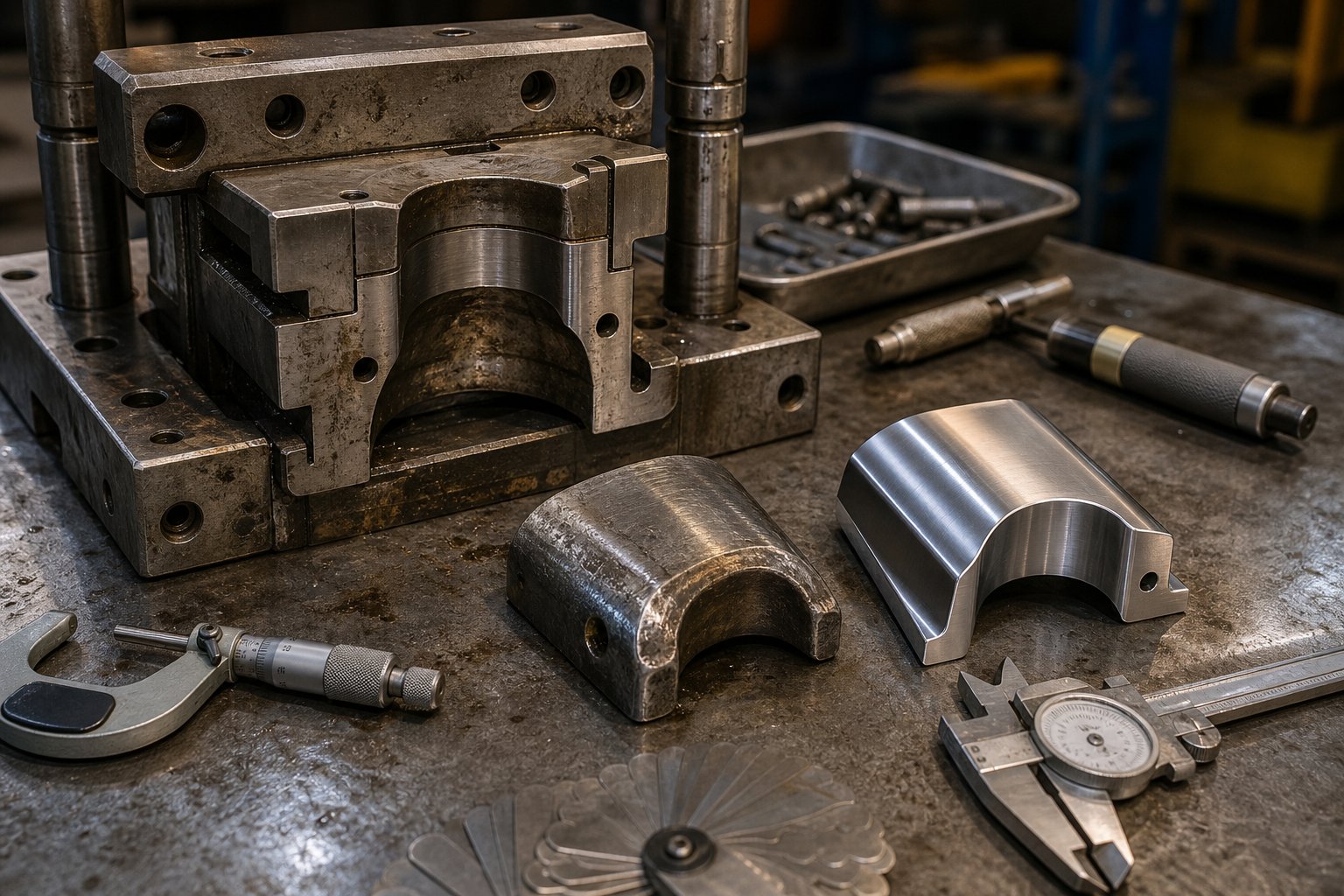
Tooling Maintenance and Die Lifecycle Management
Transfer dies earn their keep over hundreds of thousands, sometimes millions, of strokes. But the geometric freedom that makes them valuable also creates unique wear patterns that differ fundamentally from what you would see in progressive tools running the same materials. Understanding those patterns and managing them proactively is what separates a die that delivers consistent parts for five years from one that drifts out of tolerance within months.
Common Wear Patterns in Transfer Dies
Transfer dies concentrate forming forces at independent stations, each subjected to different stress profiles. The wear signatures follow predictable patterns:
- Draw radii erosion: The entry radius on draw and re-draw stations sees the highest material flow. Abrasive wear gradually rounds the radius profile, changing material flow characteristics and increasing wall thinning. This is typically the first station to need attention.
- Punch edge dulling: Piercing and trimming stations lose their cutting edges progressively. Industry data suggests that over 60% of dimensional defects in stamped parts trace back to tool wear, with cutting-edge degradation being the primary contributor to burr formation.
- Gripper finger wear: Unlike progressive stamping tool setups where the strip provides its own transport, transfer dies rely on fingers that engage the part thousands of times per shift. Contact surfaces wear, clamping force degrades, and positional accuracy drifts. Finger wear is unique to transfer systems and often overlooked during routine die inspection.
- Blank holder surface galling: Draw stations processing stainless steel or aluminum develop adhesive wear on pressure pad surfaces, where workpiece material bonds to the die face and scores subsequent parts.
The structural advantage of transfer dies is that each station wears independently. A draw station processing heavy material flow degrades faster than a downstream piercing station seeing only localized shearing force. You can pull and service a single high-wear station without dismantling the entire tool, something impossible with an integrated progressive stamping machine where all operations share one die block.
Preventive Maintenance Scheduling
Effective scheduling for transfer dies follows stroke-count triggers rather than calendar intervals, because stations wear at different rates depending on the operation they perform. A draw station might need radius inspection every 50,000 strokes while a coining station holds tolerance for 200,000.
- Every production run: Visual check of part quality at each station, gripper engagement verification, and lubrication system confirmation.
- Every 25,000-50,000 strokes: Draw radii measurement against original spec, cutting-edge inspection under magnification, gripper finger clamping force verification, and fastener torque checks on high-shock stations.
- Every 100,000-250,000 strokes: Full station disassembly of high-wear positions, surface regrinding of draw radii, punch replacement at trim and pierce stations, and transfer rail alignment verification.
- Every 500,000+ strokes: Complete teardown of all stations, die shoe resurfacing, guide system replacement, and transfer mechanism overhaul including rail straightness, finger tooling, and cam or servo drive calibration.
Die sensors and in-press monitoring systems accelerate the shift from time-based to condition-based maintenance. Force sensors embedded in draw stations detect tonnage creep that signals radius wear. Proximity sensors on transfer rails flag positional drift before it produces defective parts. Preventive maintenance research confirms that stroke-count-based triggers, calibrated against actual wear data rather than arbitrary intervals, consistently outperform fixed schedules in reducing both unplanned downtime and unnecessary service events.
Extending Die Life Through Proactive Management
Die lifecycle management starts at the design phase, not after the first failure. Engineers who plan for wear from the beginning specify harder tool steels at high-flow stations, apply PVD coatings to draw radii, and design modular inserts that can be replaced without re-machining the entire die block.
Key practices that extend the service life of transfer dies:
- Design replaceable inserts at all draw radii and high-wear contact surfaces so regrinding or replacement does not require full station teardown.
- Specify surface treatments (TiCN, CrN, or nitriding) on stations processing stainless steel or aluminum to resist adhesive wear.
- Maintain dedicated finger tooling sets per job so changeover does not force reuse of worn grippers.
- Track wear data per station independently, building a history that predicts service intervals with increasing accuracy over time.
- Document every maintenance action with stroke count, findings, and corrective steps to create a closed-loop improvement cycle.
Working with an experienced transfer die supplier makes a measurable difference here. YICHEN designs transfer stamping dies with wear management built into the tooling architecture from the start, considering how larger and more complex metal parts requiring robotic transfer will degrade over production life. Their emphasis on stable repeatability means maintenance intervals are predictable rather than reactive, and engineers can plan service windows around production schedules instead of scrambling after unexpected quality drift.
The bottom line: transfer die maintenance is not harder than maintaining progressive tools, but it is different. The modularity that gives you geometric freedom also gives you targeted maintenance capability. Use it. Track wear per station, service the stations that need it, and leave the rest running. That station-level granularity is the lifecycle management advantage that makes transfer dies a long-term production asset rather than a short-lived consumable.
Frequently Asked Questions About Transfer Die Stamping
1. What is the difference between transfer die stamping and progressive die stamping?
The core difference lies in how the workpiece moves through forming stations. In transfer die stamping, the blank is separated from the metal strip and moved by mechanical grippers or robots through independent die stations as a free-floating part. In progressive die stamping, the part remains attached to a carrier strip throughout all operations. This distinction means transfer dies handle deep draws beyond 3.5:1 ratios, parts up to 1,500 mm, and multi-axis forming, while progressive dies offer faster cycle rates of 40-100+ SPM but limit draw depth to roughly 1.0-1.5 times punch diameter.
2. How fast does a transfer die stamping press run compared to other stamping methods?
Transfer die stamping presses typically operate at 10 to 30 strokes per minute (SPM), depending on part size and transfer mechanism type. Two-axis systems reach 25-45 SPM for simpler parts, three-axis systems run 15-30 SPM, and robotic transfer lines operate at 8-20 SPM. The speed bottleneck is not forming force but the time required for grippers to complete their lift-advance-lower-retract cycle. Servo-driven presses can improve this by dwelling at top dead center, giving the transfer system extra milliseconds without reducing overall output.
3. What types of parts are best suited for transfer die stamping?
Transfer die stamping excels with parts that are too large, too deep, or too geometrically complex for progressive dies. Ideal candidates include deep-drawn shells like fire extinguisher bodies, large automotive structural pillars, appliance drums, oil pans, and any component where draw depth exceeds 1.5 times blank diameter. Parts requiring multi-axis forming, rotation between stations, or in-die secondary operations like tapping and welding also benefit. The process handles material thicknesses from 1.0 to 6.0 mm in steels, aluminum, stainless, copper, and brass alloys.
4. What are the main design rules for transfer die stamped parts?
Key design rules include maintaining hole-to-edge distances of at least 2.0 times material thickness, hole-to-hole spacing of 2.0t minimum, and hole-to-bend distances of 2.0t plus the bend radius. Minimum hole diameter should equal material thickness. Flange length needs at least 4t, and gripper contact zones require 5 mm of flat unformed surface at part edges. For draw operations, single-draw ratios max out around 2.0:1 for deep-draw steel, with re-draw stations needed when depth exceeds 1.5 times punch diameter. Each re-draw should reduce diameter by no more than 20-25%.
5. How do you maintain transfer dies to maximize their service life?
Transfer die maintenance follows stroke-count triggers rather than calendar intervals, with each station tracked independently. Draw radii should be inspected every 25,000-50,000 strokes, full station disassembly of high-wear positions occurs at 100,000-250,000 strokes, and complete teardowns happen beyond 500,000 strokes. Critical wear points include draw radii erosion, punch edge dulling, and gripper finger degradation. Designing replaceable inserts at high-wear surfaces, applying PVD coatings for abrasive materials, and using in-press force sensors for condition-based monitoring all extend die life significantly. Suppliers like YICHEN design wear management into the tooling architecture from the start.


