


What Making a Stamping Die Actually Involves
Every metal bracket in your car, every connector in your phone, and every panel on your refrigerator started inside a stamping die. These precision tools are responsible for transforming flat sheet metal into functional components at speeds that no other forming method can match. But what is metal stamping, really, and what does it take to build the tool that makes it happen?
What Is a Stamping Die
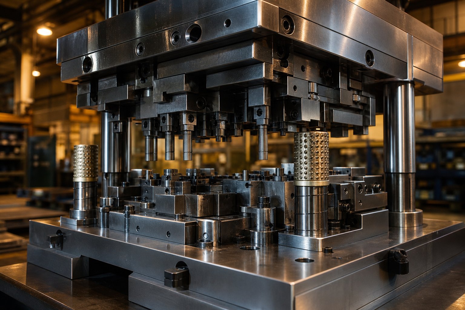
A stamping die is a precision tool consisting of two halves - an upper and lower assembly - mounted inside a press to cut, bend, form, or draw sheet metal into a specific shape through controlled force.
That stamping definition covers the basics, but the reality runs deeper. A die performs four core functions during each press cycle: locating the material, clamping it in place, working it into shape, and releasing the finished piece. The "working" phase is where value gets added - through operations like cutting, bending, piercing, embossing, forming, drawing, stretching, coining, and extruding. Making a stamping die means engineering all of these actions into a single, repeatable tool that can survive millions of press cycles.
Hobbyist vs Professional Die Making
There is a wide gap between stamping DIY projects and professional toolroom work. A hobbyist might shape a simple punch and die block using a drill press, manual mill, and bench grinder. That approach works for low-volume craft projects or prototypes where tolerances are generous.
Professional die making is a different discipline entirely. Toolrooms rely on CNC milling machines for complex cavity profiles, wire EDM for tight-tolerance openings, surface grinders for flatness down to microns, and coordinate measuring machines to verify every dimension. The difference between these two worlds comes down to repeatability - a professional stamping die must produce identical parts at hundreds of strokes per minute without deviation.
Why Precision Matters in Die Construction
Industries like automotive, electronics, and home appliances depend on metal stamping dies to hold tolerances that keep assemblies fitting together across millions of units. A connector terminal that is 0.05 mm out of spec causes electrical failures. A body panel with inconsistent draw depth creates visible ripples after paint. What is dies in manufacturing if not the foundation that every downstream quality standard rests on?
This article covers the complete lifecycle of making a stamping die - from selecting the right die type and designing strip layouts, through machining, heat treatment, and final tryout on the press. No single guide currently walks through every stage in sequence, and that gap leaves engineers piecing together fragments from multiple sources. The sections ahead close that gap, starting with how to choose the right die architecture for your specific part and production volume.
Choosing the Right Die Type for Your Project
Selecting the right die architecture is the first real engineering decision in any die stamping project. The choice shapes everything downstream - tooling cost, cycle time, part quality, and how many operations you can consolidate into a single press setup. Think of it this way: you would not use a progressive die for 500 prototypes, and you would not run a million automotive brackets through a single-station tool. Matching the types of stamping dies to your specific production goals prevents wasted budget and avoids bottlenecks on the shop floor.
| Die Type | Best For | Part Complexity | Volume Range | Relative Cost | Tooling Lead Time |
|---|---|---|---|---|---|
| Single-Station | Prototypes, short runs | Low (one operation) | Under 10,000 | Low | 2–4 weeks |
| Compound | Flat parts needing multiple cuts in one stroke | Low to moderate | 10,000–500,000 | Medium | 4–8 weeks |
| Progressive | High volume stamping of complex parts | Moderate to high | 500,000–10M+ | High | 10–20 weeks |
| Transfer | Large or deep-drawn parts | High | 100,000–5M+ | High | 12–24 weeks |
Single-Station and Compound Dies
A single-station die performs one operation per press stroke - a blank, a pierce, or a single bend. The die process is straightforward: material goes in, one feature gets formed, part comes out. This simplicity translates to low tooling costs (typically 50–70% less than progressive tooling) and fast turnaround, making single-station dies practical for pilot projects, engineering samples, or custom parts with generous tolerances.
Compound dies raise the bar by performing multiple cutting operations simultaneously in a single stroke. Imagine blanking an outer profile and piercing interior holes at the same time - that is what a compound die delivers. Because both operations share the same press cycle, concentricity between features improves significantly, and production time drops by 25–30% compared to running each operation separately. The tradeoff is that compound dies work best for relatively flat parts, typically under 150 mm in diameter, where all operations occur in a single plane.
Progressive Dies for High-Volume Runs
When production volumes climb into the hundreds of thousands or millions, progressive dies become the workhorse. Strip material feeds through a series of stations, each performing a specific operation - piercing, notching, forming, bending - until a finished part separates at the final station. The engineering logic is simple: by eliminating part handling between operations, you cut labor costs by up to 40% and achieve cycle rates that single-station setups cannot touch.
Automotive stamping dies are frequently built as progressive tools for exactly this reason. Connectors, brackets, heat shields, and structural clips all benefit from the high throughput and tight station-to-station registration that progressive dies provide. The higher upfront investment pays back quickly when per-part cost matters more than tooling cost.
Transfer Dies and When They Outperform Progressive Tooling
Transfer stamping uses mechanical grippers or fingers to move individual blanks between independent stations. Unlike progressive dies, there is no continuous strip connecting the part through the tool. This gives transfer dies a distinct advantage for parts that require deep draws, large footprints, or complex three-dimensional forming that would be impractical on a strip.
In automotive stamping, large structural components and body panels often run in transfer dies because the part geometry demands station independence. Each station can host a dedicated forming operation without the constraints of a carrying web. Transfer dies also reduce material waste since there is no connecting strip skeleton to discard - a meaningful cost saving when running expensive alloys or thick-gauge stock.
The decision between progressive and transfer ultimately comes down to part geometry and material utilization. If the part stays connected to a strip without distortion, progressive wins on speed. If the part needs to move freely between heavy forming operations, transfer stamping delivers better results with fewer quality compromises. Matching the die type to these realities is what separates efficient stamping dies from tools that fight their own design.
Stamping Die Components and How They Work Together
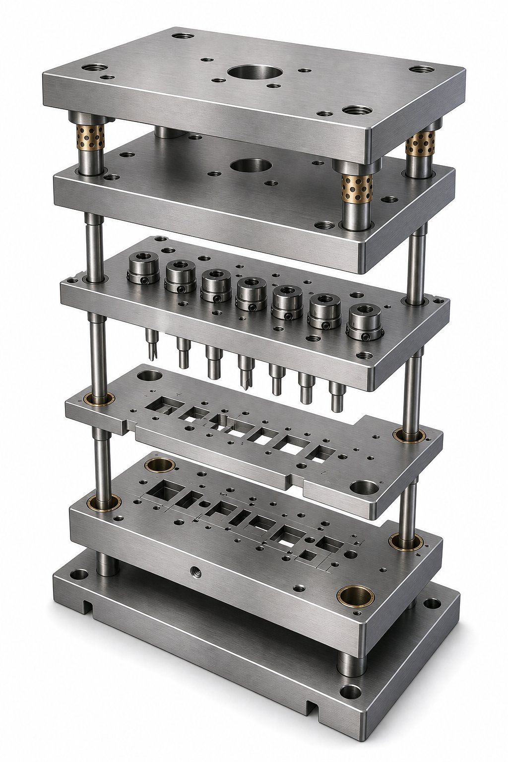
Picking the right die type sets the architecture, but performance lives in the individual stamping die components that fill that architecture. Every piece inside the tool has a job - locating, cutting, forming, stripping, or guiding - and when one element is out of spec, the entire system suffers. Understanding what each part does, and how they interact, is what separates a reliable sheet metal stamping die from one that produces scrap after a few thousand hits.
Here are the core stamping components found in most dies and stamping assemblies:
- Die shoes (upper and lower plates) - The structural foundation that holds every other component in alignment.
- Die block (cavity) - The hardened steel block containing the cutting or forming profile that accepts the punch.
- Punch plate - Holds and positions individual punches in precise locations relative to the die block.
- Backing plate - A hardened plate behind the punch plate that prevents punch heads from embedding into the softer shoe under repeated impact.
- Guide pins and bushings - Align the upper and lower halves with accuracy within tolerances of 0.0001 inches, ensuring consistent registration stroke after stroke.
- Stripper plate - Holds the workpiece flat and strips material off the punches during the return stroke.
- Spring systems - Provide controlled force for stripping, pressure pad actuation, and material clamping.
- Pilots - Precision pins that enter previously pierced holes to locate the strip accurately at each station.
- Fasteners and dowels - Secure and precisely locate all plates relative to each other, preventing shift under load.
Upper and Lower Die Shoe Assemblies
The die shoes form the skeleton of the entire tool. The upper shoe mounts to the press ram, the lower shoe bolts to the press bed, and guide posts connect the two halves to maintain alignment through millions of cycles. You can either buy a standard die set - a pre-machined assembly of shoes, guide posts, and bushings built to catalog dimensions - or design a custom die structure from scratch.
Standard die sets, like those from suppliers such as Anchor Danly, offer interchangeable components and fast delivery. They work well for conventional punching stamping operations where part sizes and press tonnages fall within standard ranges. Custom-built structures become necessary when the die requires non-standard guide post configurations, oversized footprints, or extreme precision - for example, dies stamping thin-gauge materials under 0.010 inches or running above 200 strokes per minute.
The economics are straightforward. Building die shoes in-house ties up high-value CNC machines on relatively low-margin work. For most shops, purchasing a standard set and machining it to accept your specific details saves time and cost compared to fabricating from raw plate.
Punch, Die Block, and Clearance Relationships
The relationship between punch and die block is where cutting quality gets defined. When a punch descends into the die opening, the material shears along narrow bands at both the punch edge and the die edge. The gap between those two cutting edges - the clearance - determines whether you get a clean part or a reject.
For steel workpieces, recommended clearance runs 5-10% of material thickness per side. A 1.0 mm steel sheet, for instance, needs roughly 0.05 to 0.10 mm of space between the punch edge and die button edge on each side. The exact percentage depends on workpiece hardness and tensile strength - softer materials like aluminum sit at the low end, while high-strength steel pushes toward 10% or higher.
Get this wrong and three problems appear:
- Too little clearance - Excessive shear force accelerates punch wear, generates heat, and can fracture tooling outright.
- Too much clearance - The material bends rather than shears cleanly, producing heavy burrs and rollover on part edges.
- Uneven clearance - Misalignment between punch and die block creates tapered cuts and inconsistent burr height, leading to premature wear on one side of the tooling.
Proper clearance also reduces the force required to shear the workpiece, which lowers press energy consumption and extends the intervals between die stamps regrinding. In metal stamping dies designed for high-volume production, even a 1-2% deviation from optimal clearance can cut tool life by 30% or more.
Strippers and Spring Systems
After a punch penetrates the workpiece, the material grips the punch on the return stroke. Without a stripper, the sheet lifts with the punch, misfeeds at the next station, and jams the tool. Strippers solve this by holding the material flat against the die face while the punch withdraws upward.
Two main types exist for sheet metal stamping applications. Fixed strippers are bolted rigidly in place with a gap machined to clear the material - simple, durable, but offering no downward clamping pressure. Spring-loaded strippers press the material flat before the punch contacts it and maintain pressure throughout the stroke, improving cut quality and part flatness.
The springs driving these strippers come in two forms. Mechanical die springs - color-coded helical coils - are the standard choice for moderate loads. Nitrogen gas springs deliver higher force in a smaller package and provide more consistent pressure across the full stroke, making them preferred for deep forming and drawing operations where uniform blank holding force is critical.
Selecting the right spring preload and travel matters. Underloaded springs allow the material to lift during punching, creating burrs and slug pulling. Overloaded springs waste press tonnage and accelerate fatigue. The spring system must balance stripping force against the total available press capacity - a calculation that ties directly back to the number of active stations and the combined cutting perimeter across all punches in the tool.
Each of these components gets manufactured from specific tool steel grades, machined to tight tolerances, and then hardened to resist the repetitive impact loads that production stamping demands. The choice of steel - and how it gets treated - is what ultimately determines whether a die survives its target life or wears out prematurely.
Selecting Die Steel and Materials for Longevity
A die built from the wrong steel grade is a die with an expiration date stamped on it from day one. The geometry can be perfect, the clearances dialed in, and the strip layout optimized - but if the tool steel cannot handle the forces, temperatures, and abrasion it faces every stroke, premature wear or catastrophic cracking will shut production down. Choosing the right metal stamping materials is not a secondary decision. It is the single biggest factor in whether a die survives 50,000 hits or 5,000,000.
The challenge is that no single steel grade handles every situation. A blanking punch cutting stainless steel stamping operations needs extreme wear resistance, while a forming station drawing aluminum stampings prioritizes toughness and surface finish over hardness. You need to match the steel to three variables simultaneously: the workpiece material, the operation type, and the expected production volume.
Tool Steel Grades for Different Workpiece Materials
Five tool steel grades cover the majority of stamping die applications. Each occupies a different position on the hardness-versus-toughness spectrum, and understanding where each one excels prevents costly mismatches.
| Steel Grade | Hardness Range (HRC) | Best For | Expected Die Life Range | Relative Cost |
|---|---|---|---|---|
| D2 | 58–62 | Blanking and piercing stamped steel; high-wear cutting operations | 500,000–2,000,000+ hits | Medium |
| A2 | 57–62 | General-purpose cutting and forming; moderate-volume runs | 200,000–1,000,000 hits | Low to medium |
| S7 | 54–58 | Heavy forming, bending, and impact-loaded stations | 100,000–500,000 hits | Medium |
| M2 | 60–65 | High-speed piercing; abrasive workpieces like AHSS | 1,000,000–3,000,000+ hits | High |
| DC53 | 60–62 | Heavy blanking of thick or high-strength materials | 1,000,000–3,000,000 hits | Medium to high |
D2 is the workhorse of stamping die construction. Its high chromium content (approximately 12%) creates abundant carbide structures that resist abrasive wear. For blanking and piercing operations on mild and medium-carbon stamped steel, D2 delivers long service life at a reasonable cost. The tradeoff? Those same large carbide pools that boost wear resistance reduce impact toughness. D2 punches in thin cross-sections or sharp corners are prone to chipping under heavy shock loads.
A2 offers a more forgiving alternative. It is an air-hardening steel with better dimensional stability during heat treatment than D2, and it tolerates moderate impact without cracking. For shops running medium-volume production - roughly 100,000 to 1,000,000 parts - A2 provides an economical balance between performance and cost. It machines more easily before hardening and distorts less afterward, which reduces finish grinding time.
S7 sits at the toughness end of the spectrum. When the die performs heavy forming, deep bending, or any operation where sudden impact loading dominates, S7 absorbs shock energy without fracturing. Forming stations that shape thick-gauge steel or high-strength alloys often specify S7 because it resists the type of cracking that would destroy a harder, more brittle grade. The sacrifice is wear life - S7 wears faster than D2 under abrasive conditions and typically needs more frequent regrinding.
M2 high-speed steel brings extreme hardness (up to 65 HRC) and retains its cutting edge even at elevated temperatures. For piercing operations running at high stroke rates, or when cutting advanced high-strength steel and other abrasive workpiece materials, M2 outlasts conventional cold-work steels by a wide margin. The cost premium is significant, so M2 tends to appear as individual punch inserts rather than full die blocks.
DC53 is a modified cold-work steel developed to address D2's main weakness. It achieves similar hardness (60–62 HRC) with roughly double the toughness of standard D2, thanks to a finer, more uniform carbide distribution. For blanking thick-gauge steel or high-tensile materials where both wear resistance and shock resistance matter, DC53 fills the gap that D2 and S7 leave between them.
The workpiece material drives a large part of the selection logic. Stamping soft materials like aluminum requires less wear resistance but demands excellent surface finish to prevent galling - aluminum metal stamping operations often benefit from polished A2 or coated tool steels rather than raw D2. Stainless steel stamping is the opposite extreme: the material is abrasive, work-hardens rapidly, and generates significant heat, which calls for high-chromium or high-speed steels with robust surface coatings. Mild and low-carbon stamped steel falls in the middle, where D2 handles the vast majority of blanking and piercing work without issue.
Carbide and Powder Metallurgy Alternatives
When production volumes push into the millions, or when the workpiece material is especially abrasive, conventional tool steels reach their practical limits. That is where carbide and powder metallurgy (PM) steels enter the picture.
Tungsten carbide inserts offer wear resistance that extends die life by 500–1,000% compared to traditional tool steels in certain applications. They excel in fine blanking, precision piercing of thick materials, and any station where the punch or die opening experiences continuous abrasive contact. The catch is brittleness - carbide cannot tolerate side loads, misalignment, or heavy impact. A carbide insert in a poorly supported station will fracture instantly where D2 would simply wear.
Powder metallurgy steels like ASP-60, CPM-10V, and Vanadis 4 Extra bridge the gap between conventional tool steels and carbide. The PM manufacturing process produces an extremely fine, uniform carbide distribution throughout the steel matrix, which eliminates the large carbide pools found in conventionally cast grades. The result is a material that combines near-carbide wear resistance with significantly better toughness than solid carbide. PM steels are often specified for progressive die stations that process stainless steel or advanced high-strength materials at production volumes exceeding one million hits.
For aluminium stamping applications running at very high volumes, PM steels with polished and coated surfaces solve both the wear and galling problems simultaneously. The fine microstructure takes a mirror polish more uniformly than D2, and coatings adhere better to the smoother substrate, creating a surface that resists material pickup even without heavy lubrication.
Cost vs Die Life Tradeoffs
Imagine you are quoting a job that requires 200,000 stamped aluminum parts per year. Does it make sense to specify M2 inserts and carbide buttons across every station? Probably not. A2 with a TiN coating handles that volume and operation type at a fraction of the material and machining cost.
The decision framework comes down to production volume thresholds:
- Under 100,000 parts - A2 or equivalent general-purpose steel. The die will likely retire before wear becomes critical, so paying for premium grades wastes budget.
- 100,000 to 1,000,000 parts - D2 or DC53 for cutting stations; S7 for forming stations. This is the volume range where tool steel selection starts paying dividends in reduced regrinding frequency.
- Above 1,000,000 parts - M2 or PM steels for high-wear punches, carbide inserts for the most abrasive stations, and surface coatings across the board. The higher upfront cost pays back through fewer die changes, less downtime, and more consistent part quality across the entire production run.
Cost also depends on machinability. Harder, more alloyed steels take longer to machine, require more expensive wire EDM time, and demand tighter control during heat treatment. A D2 die block costs more to finish than an A2 block of the same size - not just in raw material price, but in every downstream manufacturing step. When you factor in heat treatment distortion, finish grinding allowances, and the risk of cracking during hardening, the true cost gap between grades widens beyond the steel invoice alone.
The smartest approach is to mix grades within a single die. Use premium steels only where the wear or impact demands justify them - typically the cutting punches, die buttons, and forming inserts - while building the supporting structure from less expensive plate like AISI 4140 or 1045 heat-treated to 28–32 HRC. This strategy keeps total tooling cost manageable while concentrating performance where it matters most.
Steel selection sets the potential lifespan of the tool, but reaching that potential depends on how those steel components get shaped, hardened, and finished. The machining processes that transform raw tool steel into precision die geometry - and the sequence in which they happen - determine whether the material actually delivers the performance its grade promises.
Designing the Die with CAD CAM and Simulation
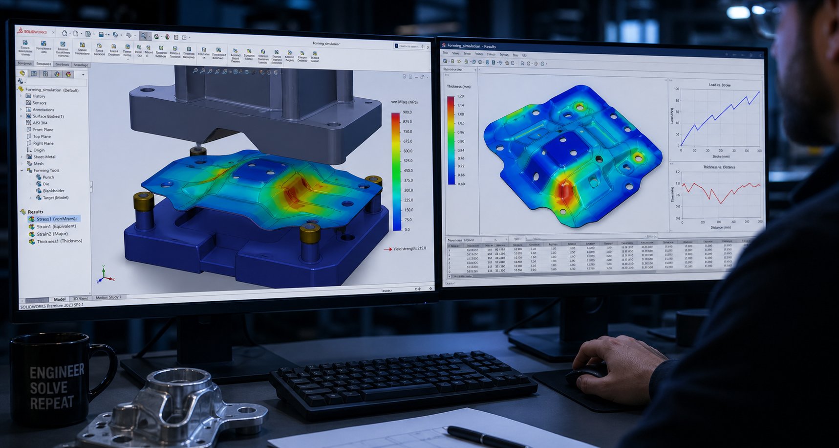
Selecting the right steel is only valuable if the die geometry actually produces a good part. The design phase is where raw intent - a finished part on a drawing - transforms into a set of machining instructions that will shape every punch, die block, and forming insert. Modern stamping die design relies on CAD/CAM software and finite element simulation to make this translation precise, predictable, and far less dependent on trial-and-error at the press.
Imagine trying to sequence twelve forming stations in your head, accounting for material stretch, spring-back, and interference between adjacent punches. That is the problem stamping technology solves digitally before a single block of tool steel gets clamped on a machine. The workflow below outlines how professional toolrooms move from part geometry to machine-ready die models.
- Part analysis - Import the finished part model and evaluate geometry for formability risks: deep draws, sharp radii, thin walls, and features close to edges.
- Process planning - Decide which operations are needed (piercing, notching, forming, trimming, coining) and assign them to categories based on sequence constraints.
- Strip layout development - Determine part orientation, pitch distance, carrier type, and material utilization on the coil strip.
- Station sequencing - Assign each operation to a specific station, balancing forces across the die and respecting forming-before-trimming rules.
- Spring-back compensation - Adjust forming tool geometry to over-bend or over-form features so the part relaxes into its intended shape after unloading.
- Interference and motion checking - Verify that no punches, strippers, lifters, or formed features collide during the press cycle.
- CAE simulation - Run formability analysis to predict thinning, wrinkling, splitting, and spring-back before any machining begins.
- Design iteration - Revise station geometry and strip layout based on simulation results until all forming stations pass acceptance criteria.
- Final die model release - Generate complete 3D die assembly with tolerances, material callouts, and CAM-ready machining geometry.
Strip Layout and Station Sequencing
Strip layout is the blueprint that dictates how the coil material moves through the die. Every decision here - part orientation relative to grain direction, pitch distance between stations, carrier width, and scrap bridge dimensions - directly impacts material utilization, force balance, and part quality over millions of cycles.
A practical sheet metal stamping design tip: orient the part so that bending occurs perpendicular to the rolling direction whenever possible. Bending with the grain creates higher risk of cracking, especially in high-strength materials. Rotating the part even 45 degrees relative to strip feed direction can improve bend ductility significantly, though it may reduce material utilization by a few percentage points.
Station sequencing follows a general logic that piercing and notching happen early - while the strip is still flat and dimensionally stable - followed by forming and bending operations in the middle stations, with final trimming and cutoff at the end. This order prevents formed features from distorting previously pierced holes and keeps the strip flat enough for pilots to register accurately.
Force balancing across stations matters more than most engineers realize. If all heavy blanking operations cluster on one side of the die, the resulting off-center load twists the press ram and causes uneven wear on guide components. Good metal stamping die design distributes cutting and forming forces symmetrically around the die centerline, or introduces idle stations to even out the load path.
Modern die design software, like Logopress DieDesign and similar CAD platforms, automates much of this layout work. Designers can test multiple strip configurations digitally, compare material utilization percentages, and visualize how the strip behaves as it feeds through the tool - all before committing to a final arrangement.
CAE Simulation for Formability and Spring-Back
Sounds complex? It is - and that complexity is exactly why CAE simulation has become non-negotiable in professional stamping design. Finite element analysis predicts what will happen to the sheet metal at every station: where it will thin excessively, where wrinkles will form due to compressive stress, where splits will initiate, and how much the part will spring back after the tooling releases it.
Spring-back prediction alone justifies the investment in simulation. When sheet metal bends, elastic recovery causes the material to partially unbend after the punch withdraws. The amount depends on material strength, bend radius, and thickness - and for advanced high-strength steels, the deviation can exceed several degrees. As research into kinematic hardening models has shown, accurate spring-back prediction requires tension-compression data and unloading modulus measurements that go well beyond basic material cards. Without this data, simulation results diverge significantly from shop-floor reality.
The practical payoff is substantial. Each physical tryout iteration on a progressive die can cost $5,000 to $25,000 in press time, measurement labor, and rework machining. Catching a thinning problem or a wrinkling condition digitally - before the die block is even roughed out - eliminates those iterations. Progressive die simulation tools like ProgSim act as virtual tryout presses, providing formability results including automatic blank development and pad-force optimization through the full press cycle.
Professional die makers like YICHEN integrate feasibility analysis and CAE simulation directly into the design phase, validating formability and spring-back compensation before committing to machining. This full-service workflow - from simulation through tooling production - represents what readers should expect from a specialist partner when evaluating whether to build in-house or outsource the design-to-tryout process.
One of the best stamping design tips for engineers new to simulation: start with a one-step feasibility analysis before running a full incremental simulation. One-step solvers flatten the finished part back to a blank in seconds, highlighting areas of concern. If the one-step results look acceptable, proceed to the computationally heavier incremental analysis that models each station in sequence. This two-stage approach saves hours of solver time on parts that clearly work - and flags problematic geometry before you invest days in detailed station design.
From Digital Model to Machine-Ready Programs
Once simulation confirms that all stations produce acceptable results, the die model transitions from a design tool into a manufacturing document. CAM programming extracts machining geometry directly from the 3D die model - CNC toolpaths for milling die blocks, wire EDM profiles for punch and die openings, and grinding dimensions for flatness and parallelism specifications.
This digital thread matters because it eliminates interpretation errors. The same model that was simulated for formability generates the G-code that cuts the steel. There is no manual translation step where a programmer re-creates geometry from a 2D print. Dimensions, tolerances, and surface finish requirements flow directly from the validated design model into machine instructions.
A metal stamping prototype run - often 50 to 200 pieces - typically follows the first complete build to validate that physical parts match simulation predictions. Discrepancies between simulation and reality feed back into the model, refining material parameters and boundary conditions for future projects. Over time, this feedback loop tightens the correlation between digital predictions and press-floor results, making each successive die project faster and more predictable.
The precision of this digital-to-physical translation depends heavily on the machining processes used to cut, shape, and finish the die components. CNC milling, wire EDM, and precision grinding each play a specific role - and understanding which process handles which feature explains why modern die making produces results that manual methods never could.
Machining and Fabricating Die Components
A validated CAD model and a block of hardened tool steel sit at opposite ends of a manufacturing gap. Closing that gap - turning digital geometry into physical stamping tooling - requires a specific sequence of machining operations, each chosen for what it does best. No single process handles every feature. CNC milling roughs cavities and profiles. Wire EDM cuts punch and die openings to micron-level accuracy. Surface grinding delivers the flatness that keeps plates parallel under load. Together, these processes define modern stamping fabrication and separate professional metal tool and die work from workshop improvisation.
Here is the typical machining sequence for building a complete die assembly:
- Rough CNC milling - Remove bulk material from die blocks, punch plates, and shoe assemblies to within 0.5–1.0 mm of final dimensions.
- Stress relieving - Thermally relax residual machining stresses before finish operations to prevent warpage later.
- Semi-finish CNC milling - Bring cavity profiles, pockets, and mounting features closer to final geometry, leaving 0.1–0.2 mm for grinding or EDM.
- Wire EDM - Cut punch profiles, die openings, and tight-tolerance through-features to final dimensions.
- Sinker EDM - Form complex 3D cavities, ribs, and blind features that wire cannot reach.
- Surface grinding - Achieve flatness and parallelism on all mating surfaces (shoes, backing plates, stripper plates).
- Jig grinding or coordinate grinding - Finish precision bores for guide pins, dowel holes, and locating features.
- Polishing and bench work - Blend transitions, break sharp edges, and finish forming surfaces to required Ra values.
CNC Milling Die Blocks and Plates
CNC milling handles the majority of material removal in stamping tool and die manufacturing. Three-axis machines rough out die block cavities, pocket reliefs, and plate contours from solid tool steel billets. For complex 3D forming surfaces - draw punches, cam drivers, and contoured die inserts - five-axis milling reaches undercuts and compound angles in a single setup, eliminating multiple fixtures and the alignment errors that come with them.
What makes CNC milling indispensable for metal stamping tooling is repeatability. A programmed toolpath produces identical geometry on every die block it touches - whether you are cutting one cavity or twenty replacement inserts over the life of the tool. According to Xometry's machining resources, typical industrial CNC milling achieves tolerances of ±0.01 to ±0.05 mm depending on machine capability and setup conditions. For die components, shops routinely hold ±0.02 mm on milled profiles, with tighter features left for EDM.
Feed rates and cutting strategies differ sharply between roughing and finishing. Roughing prioritizes material removal rate - high-feed face mills and trochoidal toolpaths clear steel quickly while managing heat and tool load. Finishing passes use smaller ball-end or corner-radius cutters at reduced step-overs to achieve scallop heights under 5 microns on forming surfaces. The surface left by the finish mill often goes directly to polishing for forming stations or to grinding for flat reference surfaces.
Wire EDM for Punch and Die Profiles
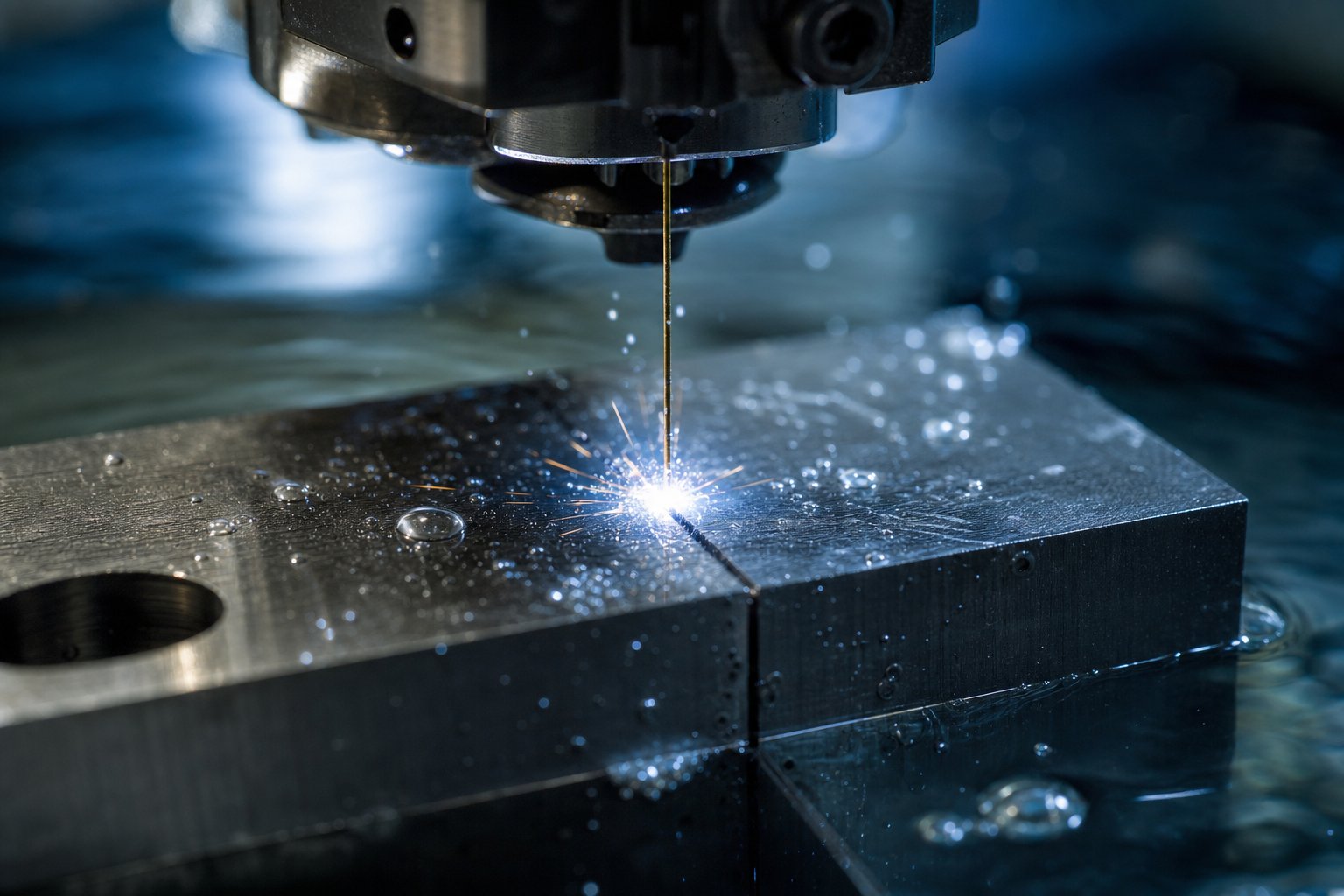
When tolerances drop below what milling can reliably hold - typically below ±0.01 mm - wire EDM takes over. This process uses a thin brass wire (usually 0.20–0.25 mm diameter) as an electrode, cutting through hardened steel with electrical discharges rather than mechanical force. Because there is no physical contact between the tool and the workpiece, wire EDM introduces zero cutting force and therefore zero deflection or distortion.
In tool and die stamping applications, wire EDM handles the features that define part quality: die button openings, punch tip profiles, and clearance relief tapers. The process cuts through fully hardened steel (60+ HRC) just as easily as annealed material - a critical advantage since many die components get machined after heat treatment when conventional cutters struggle.
Wire EDM achieves tolerances as tight as ±0.005 mm on profile cuts, with surface finishes reaching Ra 0.2 µm after multiple skim passes. A comparison from RapidDirect's EDM guide notes that wire EDM can maintain precision around 0.0001 inches (approximately 0.0025 mm), making it the process of choice for features where punch-to-die clearance must be held within a few microns per side.
Sinker EDM complements wire EDM by handling features that a wire cannot access - blind cavities, complex 3D forms, and internal corners with radii smaller than the wire diameter. In stamping machining, sinker EDM appears most often in forming inserts with compound-curved surfaces or in coining stations where a three-dimensional electrode must replicate detailed geometry into hardened steel. The tradeoff is speed: sinker EDM runs significantly slower than wire and requires a custom electrode (typically machined from graphite or copper) for each unique cavity.
Grinding to Final Tolerances
Every plate in a stamping die - upper shoe, lower shoe, backing plate, stripper plate - must be flat and parallel to a degree that milling alone cannot guarantee. Surface grinding removes the last few hundredths of a millimeter from these surfaces, achieving flatness tolerances as tight as 0.005 mm across a full plate and parallelism within 0.01 mm between opposing faces. As AB Precision Grinding notes, maintaining these geometric tolerances requires CNC-controlled grinders with sub-micron accuracy and regular wheel dressing to preserve dimensional consistency.
Surface finish requirements vary by function. Die openings and forming surfaces - where sheet metal slides under pressure - need fine finishes in the Ra 0.2 to 0.8 µm range to reduce drag, prevent galling, and minimize pickup of workpiece material. Non-functional surfaces like mounting pads and spring pockets only need reference flatness and can tolerate Ra values of 1.6 µm or rougher.
Jig grinding handles the precision bores that locate guide pins, dowels, and alignment features. These holes must maintain position accuracy within 0.005 mm and roundness within 0.002 mm to ensure repeatable upper-to-lower alignment over millions of press strokes. Coordinate grinding machines interpolate circular paths with diamond or CBN wheels, producing bore geometry that press-fit pins and bushings seat into without clearance or wobble.
The reliance on industrial metal stamping machining - CNC, EDM, and precision grinding - is what distinguishes professional die building from simplified approaches. Manual fitting with files and hand stones might produce a workable prototype, but it cannot deliver the geometric accuracy or surface consistency that production dies demand. A professional metal tool and die shop sequences these processes so that each operation builds on the precision of the previous one, culminating in components that assemble with minimal hand adjustment.
Machining brings each component to its final shape, but the steel is still in a relatively soft state for much of this work. What happens next - hardening, tempering, and surface treatment - locks in that geometry permanently and determines how well the die resists wear once it starts absorbing the repetitive shock of production stamping.
Heat Treatment and Surface Finishing Procedures
Machined die components look finished - profiles are cut, surfaces are ground, bores are located - but the steel is still relatively soft at this stage. Most tool steels ship in the annealed condition around 20 HRC, which is easy to cut but nowhere near hard enough to survive production stamping. Heat treatment bridges that gap, transforming soft ferrite into the hard martensite structure that resists wear, deformation, and fatigue across millions of press cycles. According to Eastern Tool & Stamping, heat treatment typically accounts for less than 10% of a tool's total cost yet may be the single most important factor in determining its performance.
The process is not forgiving. Skip a step, rush the cooling, or choose the wrong tempering temperature, and you end up with cracked punches, warped die blocks, or steel stamping dies that wear out in a fraction of their expected life. Here is how each phase works and why precision die stamping demands strict control at every stage.
Hardening and Tempering Sequences for Tool Steel
Heat treating tool steel follows a fixed sequence: preheating, austenitizing, quenching, and tempering. Each step triggers a specific metallurgical transformation that the next step depends on.
Preheating brings the steel gradually to an intermediate temperature - typically 1200 to 1250°F (649 to 677°C) for D2 - before the final ramp to hardening temperature. Tool steels have low thermal conductivity, so jumping straight to 1850°F risks thermal shock. If the surface heats much faster than the core, internal stress builds until the part cracks. Preheating equalizes the cross-section and lets the transformation to austenite happen uniformly.
Austenitizing dissolves alloy carbides into the steel matrix. For D2, the typical range is 1795 to 1875°F (980 to 1025°C) with a soak time of 45 to 60 minutes per inch of thickness. Too low a temperature leaves carbides undissolved and hardness low. Too high promotes grain coarsening and excessive retained austenite.
Quenching cools the austenite fast enough to form martensite. D2 and A2 are air-hardening steels - controlled air cooling or gas quenching is sufficient and produces less distortion than oil or water quenching. Lower-alloy grades like S7 may require more aggressive cooling. The steel should reach approximately 125 to 150°F before tempering begins.
Tempering relieves the extreme internal stress of freshly formed martensite. As-quenched D2 can reach 64 HRC but is dangerously brittle. Double tempering at 900 to 960°F (480 to 515°C) brings the hardness to a practical 58 to 60 HRC while improving toughness and dimensional stability. Triple tempering is recommended for high-alloy grades or when maximum control of retained austenite is critical - D2 in precision die stamping applications often receives three temper cycles because its high chromium content traps residual austenite that only converts on subsequent cooling. Each cycle must include cooling completely to room temperature before the next temper begins.
A2 behaves differently. Its lower alloy content means less retained austenite after quenching, which translates to more predictable size change and better dimensional stability than D2. For shops that need tight geometric control without post-hardening surprises, A2 is the safer choice - it requires less aggressive cryogenic intervention and responds well to standard double tempering.
Managing Dimensional Change After Heat Treatment
Every tool steel grows during hardening. The structural transformation from austenite to martensite involves a volume increase - typically 0.0005 to 0.002 inches per inch of original length, depending on grade, austenitizing temperature, and quench method. This is why finish grinding happens after heat treatment, not before. Grinding a component to final tolerance in the soft state and then hardening it guarantees that the part will be oversized and distorted when it comes out of the furnace.
The practical workflow sequences machining and heat treatment like this: rough machine in the annealed state, stress relieve, semi-finish machine leaving grinding stock (typically 0.1 to 0.25 mm per surface), harden and temper, then finish grind to final dimensions. This sequence ensures that every critical tolerance - die opening size, punch profile, flatness, parallelism - gets established on the hardened part where it will remain in service.
Cryogenic treatment adds another tool for controlling retained austenite. Cooling hardened steel down to approximately -196°C forces residual austenite to transform, which improves dimensional stability in service and prevents unexpected growth over time. For high precision metal stamping dies that must hold tolerances across years of production, cryogenic treatment between temper cycles reduces the risk of gradual size drift that throws clearances out of spec.
Design-induced cracking is another hazard. Sharp internal corners, blind holes, and sudden section changes concentrate thermal stress during quenching. Tooling engineers must design die components with heat treatment in mind - adding generous radii, avoiding drastic thickness transitions, and orienting features to promote uniform cooling.
Surface Coatings That Extend Die Life
Heat-treated tool steel provides the hardness foundation, but surface coatings add a final layer of protection that dramatically extends service life - especially for stamping tool material running against abrasive or adhesion-prone workpiece metals. A study published in Micromachines demonstrated that TiAlN PVD coating on D2 stamping dies increased reconditioning intervals from 80,000 cycles to an estimated 500,000 cycles - a lifetime gain exceeding 500%.
The coating choice depends on the workpiece material and the dominant wear mechanism:
- TiN (Titanium Nitride) - General-purpose coating for carbon steel stamping and cold rolled steel stamping operations. Hardness around 2,300 HV. Reduces adhesive wear and provides a low-friction gold surface. Best for blanking and piercing mild steel at moderate volumes.
- TiCN (Titanium Carbonitride) - Higher hardness than TiN (approximately 3,000 HV) with better abrasion resistance. Suits stainless stamping and higher-strength workpiece materials where sliding wear dominates.
- TiAlN (Titanium Aluminum Nitride) - Excellent performance at elevated temperatures due to aluminum oxide formation on the surface during use. The PVD study cited above measured a friction coefficient of just 0.18 for TiAlN versus 0.74 for uncoated steel against tinplate. Ideal for high-speed operations and stainless steel metal stamping where heat buildup accelerates wear.
- Nitriding - A diffusion process that hardens the surface layer to 65–70 HRC without adding a discrete coating. Creates a hard case 0.1 to 0.3 mm deep. Works well for forming and bending stations where coating adhesion under deformation loading is a concern.
- Hard chrome plating - Low friction and excellent release properties make chrome ideal for drawing dies where sheet metal must slide smoothly over large radii without galling. Commonly specified for stainless stamping and aluminum drawing operations.
One engineering detail that trips up less experienced shops: the tempering temperature of the base steel must exceed the coating deposition temperature. PVD coatings deposit at approximately 400 to 500°C. If the die was tempered below that range, the coating process itself will over-temper the substrate, softening it and destroying the hardness you worked so hard to achieve. For D2 double-tempered at 480 to 515°C, standard PVD deposition temperatures are compatible - but this must be verified before sending parts to the coater.
Surface treatment is the final step before assembly. With hardened, ground, and coated components in hand, the die is ready to be bolted together for its first trial run on the press - where the real proof of every material choice, every tolerance, and every heat treatment decision reveals itself in the quality of the stamped parts it produces.
Die Tryout and Troubleshooting After Assembly
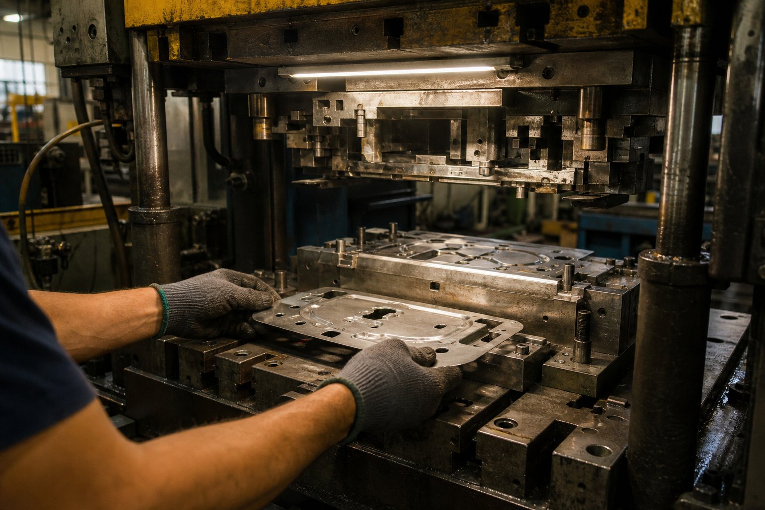
Every design assumption, material choice, and machining tolerance gets tested the moment a die closes inside a stamping machine for the first time. Tryout is where theory meets metal - and where problems that no simulation fully predicted reveal themselves in the form of burrs, splits, wrinkles, or parts that refuse to hold dimension. It is also the phase most commonly glossed over in die-making literature, despite being the single most expensive and time-sensitive stage of any tooling project.
How does a stamping press work during tryout? The same way it works in production - the ram descends, the upper die closes onto the lower, force is applied, and the material deforms or shears - but at reduced speed and with careful observation between each stroke. The goal is to bring the die from "first contact" to "production-ready" with as few iterations as possible.
Setting Up the Die for First Trial Runs
Before the press cycles even once, setup determines whether the tryout proceeds smoothly or fights alignment problems from the start. Here is the sequence experienced toolmakers follow when loading a die onto a die stamping press for its initial run:
- Press selection and tonnage verification - Confirm the press has adequate tonnage (typically 20-30% above the calculated cutting and forming force), sufficient shut height, and a bed area that supports the full die footprint without overhang.
- Die loading and clamping - Lift the die onto the press bed using crane or bolster, center it under the ram, and bolt the lower shoe securely. Clamp the upper shoe to the ram with T-slot bolts or hydraulic clamps.
- Shut height adjustment - Set the press shut height so the die closes to its designed position without bottoming out. Use feeler gauges or dial indicators between the upper and lower shoes at all four corners to verify uniform closure.
- Shimming and alignment check - Place a soft material like brass shim stock between the punch faces and die openings, then inch the press through a slow stroke. The impression pattern reveals whether alignment is uniform or skewed. Uneven impressions indicate that the die needs shimming under one side or that guide pin preload requires adjustment.
- Feed system setup - For progressive dies, thread coil stock through the feeder and set pilot release timing, feed length, and loop control. Verify that pilots engage cleanly without dragging or bending the strip.
- First hit at reduced speed - Run the press in single-stroke mode at reduced tonnage. Inspect the first piece visually before proceeding to consecutive hits.
The shimming step deserves extra attention. Even with precision-ground die shoes and guide posts held to microns, the press itself introduces variables - ram parallelism, bolster deflection under load, and thermal growth during warm-up all contribute to alignment deviation. Shimming compensates for the combined stack-up of press and die tolerances that no amount of bench assembly can eliminate.
Measuring and Evaluating Stamped Parts
After the first few hits produce visible parts, measurement begins immediately. You are not looking for perfection at this stage - you are identifying which stations perform correctly and which need adjustment. A systematic evaluation catches problems early before they compound across subsequent stations.
For each metal stamped part coming off the tryout press, evaluate against these criteria:
- Burr height - Measure with a micrometer or optical comparator. Acceptable burr height for most applications is under 10% of material thickness. Burrs exceeding this threshold indicate clearance or alignment issues.
- Dimensional accuracy - Check hole positions, edge distances, bend angles, and overall profile against the part print using CMM, height gauges, or optical measurement systems.
- Surface condition - Inspect for scoring, galling, die marks, or material pickup on formed surfaces. These indicate lubrication problems or insufficient die surface finish.
- Spring-back deviation - Measure bend angles and compare to nominal. Record the deviation magnitude and direction to determine how much overbend correction is needed.
- Material thinning - For draw and stretch operations, measure wall thickness at critical points. Thinning beyond 20-25% of original thickness signals a risk of splitting in production.
- Flatness and twist - Place parts on a surface plate to check for bow, twist, or oil-canning that develops after the part leaves the die.
Experienced die makers run five to ten consecutive parts and compare measurements across the set. A single part might look acceptable by coincidence, but variation across a short run exposes instability - a forming station that drifts, a pilot that does not locate consistently, or a stripper that releases unevenly.
Press stamping at production speed introduces additional variables that low-speed tryout cannot replicate. Thermal expansion, dynamic deflection, and strip feeding behavior all change at full speed. Most tryout schedules include a gradual speed ramp - starting at 10-20 strokes per minute during initial hits, increasing to 50%, then 75%, and finally full production speed - with measurement checkpoints at each stage.
Troubleshooting Common Die Problems
Even well-designed dies rarely produce perfect parts on the first hit. Tryout is fundamentally a troubleshooting exercise, and knowing the relationship between symptoms and root causes saves days of trial-and-error. The table below covers the most frequent issues encountered during stamp press tryout and the corrections that resolve them.
| Problem | Likely Cause | Correction |
|---|---|---|
| Excessive burrs on cut edges | Punch-to-die clearance too large, or cutting edges dulled from misalignment during initial hits | Verify and correct clearance per side; resharpen edges if damaged; check guide pin wear |
| Splitting at draw or form stations | Insufficient material flow due to excessive blank holder pressure, sharp die radii, or inadequate lubrication | Reduce blank holder force; increase die entry radii; apply heavier or different lubricant |
| Wrinkling on flanges or walls | Too little blank holder pressure, excessive clearance between punch and cavity, or material too thin for draw depth | Increase blank holder force; add draw beads; reduce blank size to limit excess material |
| Dimensional drift after short runs | Thermal expansion of die components, inconsistent strip feed length, or press ram deflection under load | Allow press and die to reach thermal equilibrium; recalibrate feeder; verify tonnage distribution |
| Slug pulling (slugs stick to punch face) | Insufficient angular clearance below die opening, vacuum effect on punch face, or oil film pulling slug upward | Add taper relief to die opening; install vacuum-break grooves on punch face; apply ejector pins or positive slug retention features |
| Parts sticking in die cavity | Insufficient draft angle on form surfaces, galling from poor surface finish, or inadequate knockout force | Polish die surfaces; add coating (TiN or chrome); increase knockout spring force or add air blast |
| Uneven shear band on cut edges | Die misalignment causing tapered clearance from one side to the other | Reshim die in press; inspect guide pins and bushings for wear; verify die shoe parallelism |
Slug pulling, as noted in The Fabricator's coverage of cutting problems, is one of the most persistent issues in piercing operations. When a slug rides back up with the punch, it can land on the strip surface and get stamped into the next part - creating a raised defect that ruins the piece and potentially damages the die. The fix often involves modifying the die button geometry: replacing step-relief buttons with tapered matrices that maintain positive slug control, or adding angular shear to the punch face to break vacuum.
Each correction during tryout should be documented along with the measurement data that prompted it. This record becomes invaluable later - both for reproducing the setup after maintenance and for refining the design of future dies running similar materials and geometries.
Die Maintenance and Regrinding Schedules
Tryout ends when the die consistently produces parts within specification at production speed. But the work does not stop there. A stamping machine running at 100 to 400 strokes per minute subjects the die to relentless cyclic loading, and even the hardest tool steels degrade over time. Establishing a maintenance cadence before production begins - rather than reacting to quality failures - is what separates shops that hit target die life from those that fight constant unplanned downtime.
A practical maintenance schedule follows a tiered structure based on production stroke counts and measurable quality indicators:
- Every shift - Visual inspection for cracked or chipped punches, chip buildup in die openings, lubrication verification, and scrap path clearance. These quick checks take minutes and catch failures before they cascade.
- Every 50,000 to 100,000 strokes - Measure burr height, check guide clearance, inspect stripper plate condition, and verify spring force. If burr height exceeds spec, schedule regrinding.
- Every 100,000 to 300,000 strokes - Full service including regrinding all cutting edges, replacing worn springs, checking plate flatness, and verifying die alignment with indicators. For high-volume lines or when processing high-hardness materials, shorten this interval.
- At 70-80% of expected die life - Preventive overhaul. Complete teardown, dimensional audit of all wear components, replacement of guide bushings, and evaluation of whether critical stations need insert replacement or coating renewal.
Regrinding deserves specific attention because it directly affects how long a die remains in service. Each time a cutting edge dulls beyond the acceptable burr threshold, a surface grinder removes a thin layer - typically 0.05 to 0.15 mm - from the punch face and die surface to restore sharpness. The die block and punch must be ground equally to maintain proper shut height, and shims must be added beneath the punch to compensate for the material removed.
How many regrinds can a die tolerate? That depends on the original design. Most dies include a die life allowance - extra material height built into punches and die blocks specifically to accommodate regrinding. A typical allowance ranges from 3 to 6 mm total, which translates to 20 to 60 regrind cycles before the tooling reaches its dimensional limit and requires insert replacement or full rebuild.
Monitoring quality indicators like burr height, shear band width, and force trends (rising press load often signals dulling) provides data-driven triggers for maintenance rather than relying on arbitrary calendar schedules. SPC charts tracking critical dimensions across production runs reveal gradual drift long before parts fall out of tolerance - giving you time to schedule maintenance during planned downtime rather than scrambling after a quality escape.
A die that runs through tryout successfully and enters production with a defined maintenance plan is a die positioned to reach its full design life. But not every organization has the press capacity, toolroom equipment, or experienced personnel to manage this entire process internally - which raises a practical question about when it makes sense to build in-house versus partnering with a specialist who handles the complete lifecycle from feasibility through production support.
Deciding Whether to Build or Partner for Your Stamping Die
The previous sections covered every stage of making a stamping die - design, machining, heat treatment, and tryout. Completing all of those steps in-house requires a specific combination of equipment, expertise, and bandwidth that not every organization possesses. The build-or-buy decision is not about capability alone; it is about whether your internal resources align with the complexity, timeline, and volume your project demands.
When to Build In-House vs Partner with a Die Maker
Building a custom metal stamping die internally makes sense under a narrow set of conditions. If any of these criteria fall outside your reach, partnering becomes the more reliable path to production-ready tooling.
- Equipment access - Do you have CNC milling, wire EDM, surface grinding, and a tryout press of sufficient tonnage on-site? Missing even one link forces costly outsourcing of individual steps.
- Toolroom expertise - Experienced die makers who understand the full metal stamping process - from strip layout through heat treatment sequencing - take years to develop. A team without this depth will burn time troubleshooting problems a specialist solves routinely.
- Volume and tolerance demands - Low-volume metal stamping parts with generous tolerances can tolerate an iterative in-house approach. High-volume metal stamping components requiring tight specs and long die life demand the precision that dedicated toolrooms deliver consistently.
- Timeline pressure - A full-service partner runs design, simulation, machining, and tryout in parallel workflows. In-house builds typically run sequentially, extending lead time by weeks or months.
- Risk tolerance - Every rework cycle during tryout costs press time, labor, and material. Partners who produce metal stamped parts routinely absorb that risk within their quoted scope.
What to Expect from a Full-Service Stamping Die Supplier
A capable stamping manufacturing partner covers the entire lifecycle discussed throughout this article - not just the machining. When evaluating suppliers for metal parts stamping projects, look for these capabilities under one roof:
- Feasibility analysis and DFM feedback before tooling commitment
- In-house CAE simulation validating formability, thinning, and spring-back
- Complete machining capability (CNC, EDM, grinding) with documented tolerances
- Controlled heat treatment and surface coating processes
- Tryout press with measurement and first-article inspection reporting
- Iterative support - adjustments based on trial data until parts meet spec
YICHEN is one example of a partner structured around this full-lifecycle model, covering feasibility and CAE simulation through machining, trial runs, and dimensional inspection - giving manufacturers a single point of contact from initial concept to validated production tooling. For sourcing managers and tooling engineers ready to move beyond research, their stamping die page serves as a direct path to requesting a quote on a custom metal stamping manufacturing project.
Moving from Research to an RFQ-Ready Specification
When you reach the point of requesting quotes, the quality of your specification determines the quality of the responses you receive. A strong RFQ package for a custom metal stamping die includes:
- 3D part model and 2D drawing with GD&T callouts
- Material type, thickness, and grade
- Annual volume and expected die life target
- Critical dimensions and surface finish requirements
- Any secondary operations (tapping, plating, assembly)
Providing this detail upfront allows suppliers to quote accurately, propose the right die type, and identify potential metal stamping manufacturing challenges before tooling begins - rather than discovering them during tryout when changes cost the most. The entire metal stamping process benefits when the engineering conversation starts early and both sides share complete information from the outset.
Frequently Asked Questions About Making a Stamping Die
1. How long does it take to make a stamping die?
Lead time depends on die type and complexity. A simple single-station die can be completed in 2 to 4 weeks, while a compound die typically takes 4 to 8 weeks. Progressive dies for high-volume production require 10 to 20 weeks due to multi-station design, CAE simulation, precision machining, heat treatment, and iterative tryout. Transfer dies for large or deep-drawn parts may take 12 to 24 weeks. Partnering with a full-service supplier like YICHEN can streamline timelines by running design, simulation, and machining in parallel workflows.
2. What materials are used to make stamping dies?
Stamping dies are primarily built from tool steels selected based on the workpiece material and production volume. Common grades include D2 for high-wear blanking operations, A2 for general-purpose cutting and forming, S7 for heavy impact-loaded stations, M2 high-speed steel for abrasive materials, and DC53 for thick or high-strength blanking. For extreme-volume applications exceeding several million hits, tungsten carbide inserts and powder metallurgy steels like CPM-10V provide extended wear resistance. Supporting structures typically use AISI 4140 or 1045 steel heat-treated to 28-32 HRC.
3. What is the difference between a progressive die and a transfer die?
A progressive die keeps the workpiece connected to a continuous strip that feeds through multiple stations, with each station performing a specific operation until the finished part separates at the final station. A transfer die uses mechanical grippers to move individual blanks between independent stations without a connecting strip. Progressive dies excel at high-speed production of smaller, moderately complex parts. Transfer dies are better suited for large parts, deep draws, or complex 3D forming where the part must move freely between heavy forming operations. Transfer dies also reduce material waste since there is no strip skeleton to discard.
4. How much does it cost to make a stamping die?
Cost varies widely based on die type, part complexity, and material requirements. Single-station dies for simple operations represent the lowest investment, while progressive and transfer dies for complex, high-volume parts cost significantly more due to multi-station design, CAE simulation, precision EDM and CNC machining, and extended tryout. Key cost factors include the number of stations, tool steel grade selection, surface coatings, and required tolerances. Mixing premium steels only at high-wear stations while using less expensive plate for structural components is a common strategy to control total tooling cost without sacrificing performance.
5. How do you maintain a stamping die to extend its life?
Effective die maintenance follows a tiered schedule based on stroke counts. Every shift requires visual inspection for cracked punches and chip buildup. Every 50,000 to 100,000 strokes, measure burr height and check guide clearance. Full service including regrinding all cutting edges should occur every 100,000 to 300,000 strokes. A preventive overhaul at 70-80% of expected die life includes complete teardown and dimensional audit. Each regrind removes 0.05 to 0.15 mm from cutting surfaces, and dies typically allow 20 to 60 regrind cycles before requiring insert replacement. Surface coatings like TiN and TiAlN can extend intervals between regrinds by several hundred percent.


