


Stamping and Die Casting Defined for Engineers and Buyers
Search for "stamping die casting" and you'll find these two processes lumped together as if they're interchangeable. They're not. Stamping and die casting are fundamentally different ways to turn raw metal into finished parts, and confusing them is one of the fastest routes to overpaying for tooling that doesn't match your project.
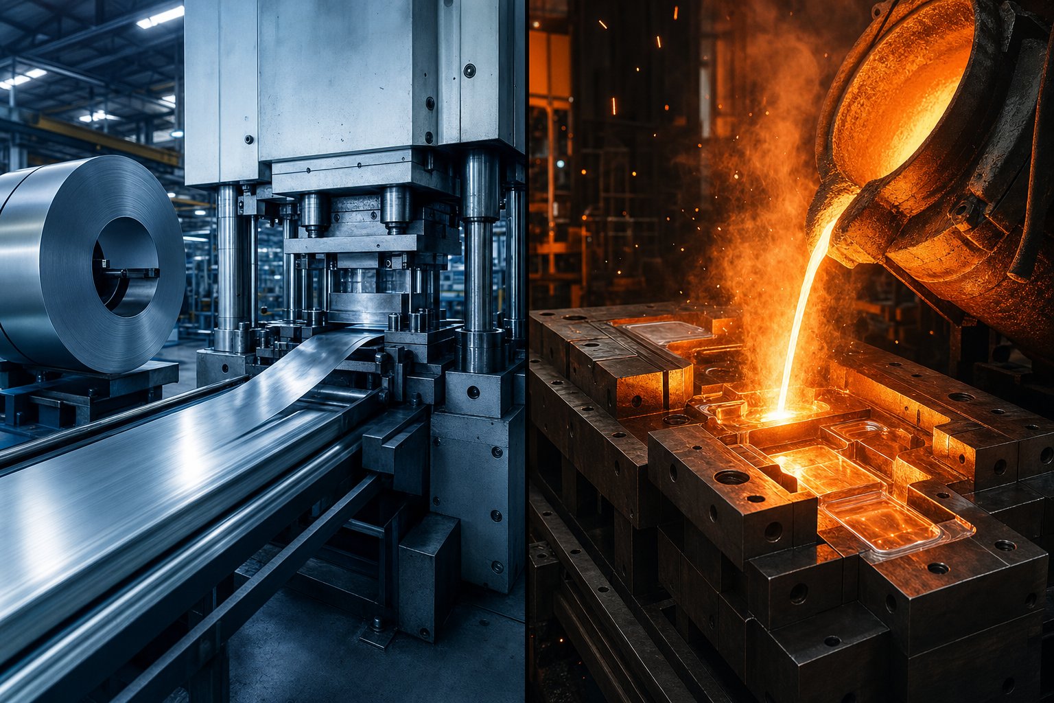
Here's the short version: stamping applies mechanical force to reshape solid sheet metal, while die casting injects molten metal into a reusable steel mold under pressure. Same goal - a precision metal component - but entirely different physics, materials, and cost structures.
What Is Metal Stamping
Metal stamping is a cold-forming process that transforms flat sheets or coils of metal into specific shapes. A punch descends into a die, and the mechanical force between them blanks, bends, draws, or pierces the sheet stock into a finished part. The material stays solid throughout - no melting involved. What is stamped metal, then? It's any component shaped this way: brackets, clips, enclosures, lead frames, or structural panels made from steel, aluminum, copper, or brass sheet.
What Is Die Cast Metal
Die casting works from the opposite direction. Instead of reshaping a solid sheet, it starts with molten alloy - typically aluminum, zinc, or magnesium - injected into a precision steel mold under high pressure. The liquid metal fills every cavity, solidifies rapidly, and emerges as a near-net-shape part with complex three-dimensional geometry. So what is die cast metal? It's any component formed by solidifying a molten alloy inside a reusable die.
Stamping reshapes solid sheet; die casting solidifies liquid metal. Every cost, design, and sourcing decision flows from this single distinction.
Getting this difference right up front determines whether you invest in the correct tooling, select appropriate materials, and hit your per-part cost targets. The sections ahead break down exactly how each process works - starting with what happens inside a stamping press from the moment a coil feeds in.
How the Metal Stamping Process Works
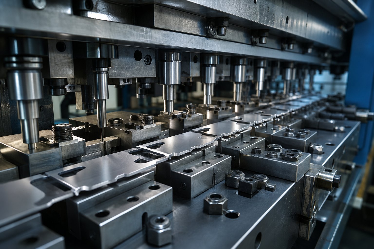
A coil of flat metal enters one end of a press, and finished parts exit the other. Sounds simple, but what happens between those two points involves precise tonnage, carefully sequenced tooling stations, and split-second timing. The die stamping machine - whether mechanical, hydraulic, or servo-driven - delivers anywhere from 20 to 6,000 tons of pressing force, depending on part size and material thickness. That force drives a punch into a die cavity to blank, pierce, bend, draw, or form the sheet stock into its final geometry.
Three core components make this possible: the sheet metal itself, the die (the shaped tooling that defines part geometry), and the press that delivers force. But the way those components interact varies dramatically based on die configuration - and picking the wrong setup can tank your production economics.
Progressive and Transfer Die Configurations
Imagine a metal strip moving through a series of stations, each one performing a different operation - a pierce here, a bend there, a final cutoff at the end. That's a progressive die. The workpiece stays attached to the carrier strip from start to finish, advancing a fixed distance (called the pitch) with each press stroke. Multiple parts are in process simultaneously, each at a different stage. Progressive dies can produce anywhere from seven or eight parts per minute to over 1,500 parts per minute, making them dominant for high-volume production of small to mid-size components with tight tolerances.
Transfer dies take a different approach. The first operation separates the blank from the strip entirely, and mechanical fingers or rails physically move that discrete part from station to station. This die transfer method opens up possibilities that progressive tooling cannot match - deep draws, part rotation between stations, and geometries that require access from multiple angles. Round, axially symmetrical parts like deep cups or shells are common transfer die candidates because the part can be lifted, rotated, and repositioned between operations.
A third option - compound dies - performs multiple cutting and forming operations in a single press stroke. They excel at producing simple flat parts like washers quickly and cost-effectively, with flatter results than progressive dies since everything happens in one hit. However, compound tooling lacks the multi-stage flexibility needed for complex shapes.
When do you choose which? Progressive dies win when you need high-speed, high-volume output of parts with moderate complexity. Transfer dies earn their place on larger parts, deep-drawn components, or anything requiring the blank to be free from the strip during forming. Compound dies suit medium-to-high-volume runs of geometrically simple parts where flatness and low tooling cost matter most.
Sheet Metal Stamping Process Step by Step
Regardless of die type, the sheet metal stamping process follows a predictable sequence. Here's what happens from raw material to finished component:
- Coil loading and straightening - The metal coil mounts on an uncoiler, feeds through a straightener to remove coil set (the natural curvature from being wound), and enters the press.
- Material feeding - A servo or mechanical feeder advances the strip a precise distance (the pitch) into the die with each press cycle. Consistency here directly controls dimensional accuracy downstream.
- Blanking - The press cuts the basic outline shape from the strip. In progressive dies, this may happen at the final station; in transfer dies, it's the first operation.
- Piercing - Punches create holes, slots, or internal features by forcing material through a die opening. The slugs are discarded while the surrounding material becomes the part.
- Forming operations - Bending, drawing, coining, or embossing stations shape the flat blank into three-dimensional geometry. Drawing uses tension to pull material into a cavity for vessel-like shapes; bending creates angular features.
- Part ejection and separation - The finished component is cut free from the carrier strip (progressive) or removed from the final station (transfer) and exits the press via chute, conveyor, or robotic pickup.
Each of these steps relies on stamping mold design - the geometry of punches, die cavities, strippers, and pilots working in concert. Well-engineered tooling delivers tight tolerances repeatedly across millions of cycles. Poorly designed tooling wears prematurely, produces burrs, and drives up scrap rates. The die is where your part quality lives or dies.
Materials commonly run through this process include mild steel, stainless steel, aluminum, copper, and brass. Each behaves differently under forming pressure - aluminum stamps cleanly but can tear during deep draws, copper offers excellent ductility for complex shapes, and stainless demands higher tonnage and more wear-resistant die steels. Specialty alloys like Inconel and titanium are also stampable in the right setup, though they require significantly more robust tooling.
All of this mechanical precision happens at room temperature. The friction between punch and sheet generates heat, but the process itself is cold-forming - a critical distinction when comparing stamping to processes that start with molten metal and an entirely different set of physics.
How the Die Casting Process Works
Stamping reshapes flat stock through brute mechanical force at room temperature. Metal die casting operates on entirely different physics - it begins with an alloy heated past its melting point, then forces that liquid into a precision steel mold under pressures ranging from 10 to 150 MPa. The result is a near-net-shape part with complex three-dimensional geometry that would be impossible to achieve by pressing sheet metal alone.
The process follows five core stages. First, the two-part steel die is prepared - cleaned, lubricated with a release agent, and clamped shut by a machine delivering hundreds or thousands of tons of locking force. Next, molten metal is injected into the die cavity at fill speeds of 10 to 50 m/s. The alloy solidifies rapidly - often in seconds - because the steel die acts as a massive heat sink. Once the part has cooled enough to hold its shape, the die halves separate and ejector pins push the casting free. Finally, the part goes through trimming to remove flash, runners, and overflow wells created during injection.
Cycle times are fast. A zinc part might go from liquid to ejected component in under 15 seconds. Aluminum takes slightly longer due to higher solidification temperatures. Either way, a single die can produce hundreds of parts per hour and survive 100,000 or more cycles before requiring replacement - which is what makes metal die casting economical at scale.
Hot-Chamber vs Cold-Chamber Die Casting
Not all die casting machines work the same way. The distinction between hot-chamber and cold-chamber systems comes down to one question: can the injection mechanism sit inside the molten metal without being destroyed?
In a hot-chamber machine, the gooseneck and plunger are submerged directly in the molten alloy. A valve allows a controlled volume of metal into the injection cylinder, and the plunger forces it through a heated nozzle into the die. Because the injection system stays immersed, cycle times are short and the nozzle remains full of molten metal between shots. Zinc and magnesium are the primary metals processed this way - their melting points (380-650 degrees C) are low enough that they won't erode the submerged steel components.
Cold-chamber machines separate the melting furnace from the injection system entirely. Molten metal is ladled or pumped into a horizontal shot sleeve, then a hydraulic plunger rams it into the die cavity. This extra transfer step adds cycle time, but it's necessary for alloys like aluminum (melting at 580-630 degrees C) and copper-based alloys that would rapidly degrade a hot-chamber gooseneck. Injection pressures in cold-chamber systems typically range from 2,500 PSI up to over 25,000 PSI.
The trade-off is straightforward: hot-chamber systems deliver faster cycles and tighter process control for low-melting alloys, while cold-chamber systems handle the higher-temperature metals that represent the bulk of structural die casting applications.
Metals Used in Die Casting
When people ask "does die cast mean metal?" - the answer is yes, but with an important qualifier. Die casting specifically means metal shaped via pressurized injection into reusable steel molds. It doesn't cover plastics (that's injection molding) and it doesn't cover just any metal. Only alloys with suitable melting points, fluidity, and solidification behavior qualify as practical die casting metals.
Here's how the major alloy families compare:
| Alloy Family | Melting Range | Chamber Type | Typical Applications |
|---|---|---|---|
| Aluminum (A380, A360, ADC12) | 580-630°C | Cold-chamber | Engine blocks, transmission housings, heat sinks, structural brackets |
| Zinc (ZAMAK 3, ZAMAK 5) | 380-420°C | Hot-chamber | Door handles, gears, connectors, decorative hardware |
| Magnesium (AZ91D, AM60) | ~650°C | Hot-chamber or cold-chamber | Laptop frames, steering wheels, camera bodies, aerospace brackets |
| Copper alloys (limited) | 900-1,080°C | Cold-chamber | Electrical components, plumbing fittings, high-conductivity parts |
Aluminum dominates the market by volume - its balance of light weight, strength, corrosion resistance, and thermal conductivity makes it the go-to for automotive and electronics. Zinc excels at intricate, thin-walled parts (wall thicknesses as low as 0.3 mm) with excellent surface finish right out of the die. Magnesium is the lightest structural option, roughly 33% lighter than aluminum, which makes it attractive for handheld electronics and weight-critical automotive components.
What about die cast steel? You'll see the term circulate, but in practice, die casting steel is not feasible with conventional equipment. Steel melts between 1,370 and 1,530 degrees C - temperatures that would rapidly destroy even hardened tool-steel dies. Steel parts requiring mold-based production typically use investment casting or sand casting instead, where expendable molds tolerate the extreme heat. The American Foundry Society reports that 95% of die cast parts use non-ferrous metals, confirming that steel simply doesn't belong in this process category.
Copper alloys occupy a small niche. Their high melting points shorten die life significantly and increase production costs, but when you need electrical conductivity and mechanical strength in a single cast component, copper-based alloys remain the only option within the die casting family.
Each of these alloys carries specific design constraints - minimum wall thicknesses, draft angles, tolerance capabilities - that dictate what's geometrically possible in your part. Those manufacturing rules are where the real process selection decisions get made.
Design Constraints and Manufacturing Guidelines
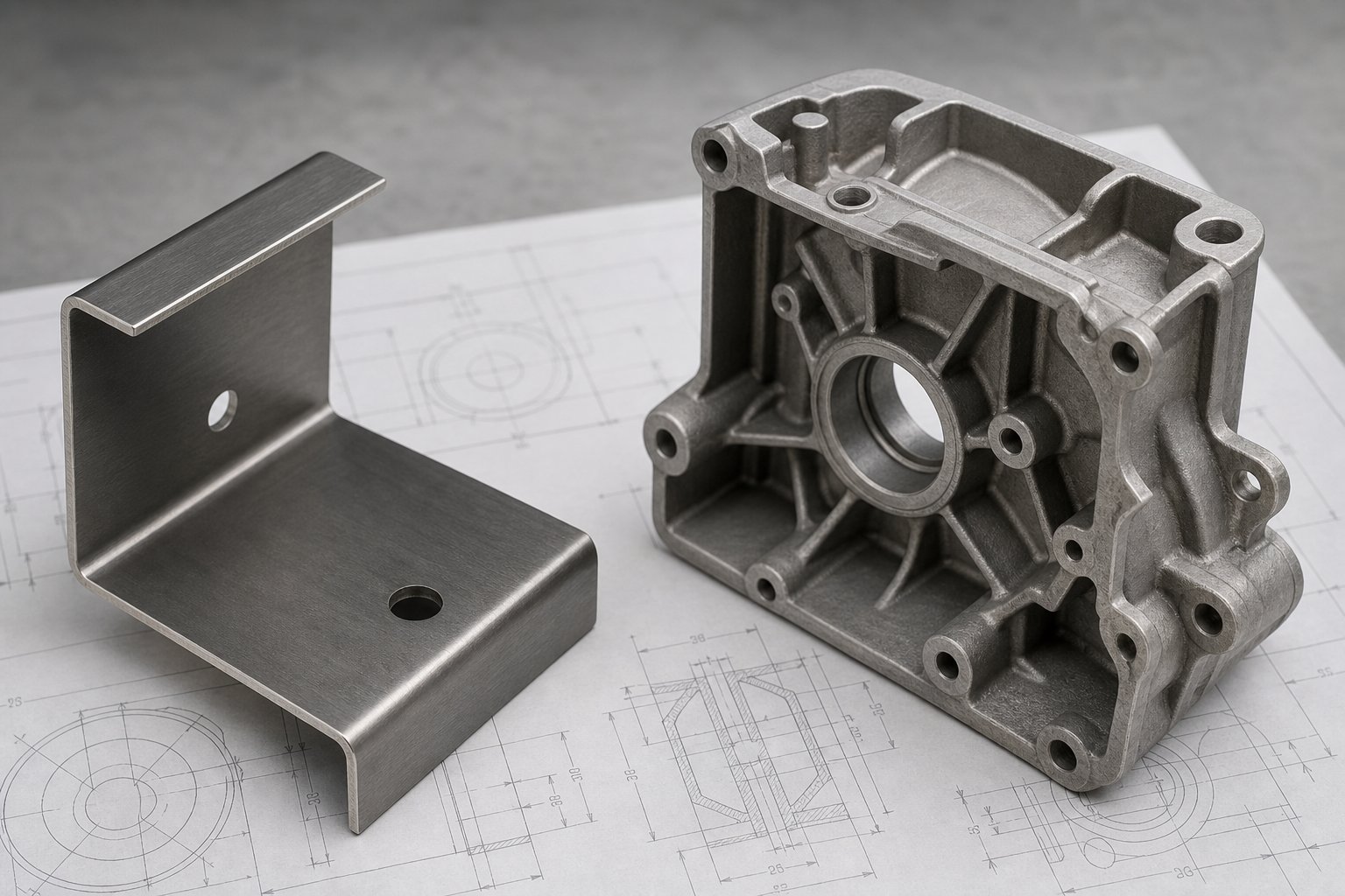
Knowing how each process works is one thing. Designing a part that actually survives production without ballooning your reject rate - that's where most projects succeed or fail. Stamping and die casting each impose strict geometric rules, and violating them doesn't just degrade quality; it can force you into the wrong process entirely. A deep-drawn feature that exceeds stamping limits might push you toward die casting, while a simple bracket designed with unnecessary three-dimensional complexity locks you into expensive casting tooling you never needed.
The practical takeaway: geometry drives process selection as much as volume or material choice. Here are the rules that matter.
Design Rules for Stamped Parts
Stamped sheet metal stays at a relatively uniform thickness throughout the part - you're reshaping a flat blank, not adding or removing material. That single constraint shapes every design decision.
Bend radius minimums. The tightest bend you can form depends directly on material type and thickness. For ductile materials like stamped aluminum sheet, the minimum inside bend radius is typically 1x the material thickness. For stamped steel sheet - especially high-strength or stainless grades - you'll need 1.5x to 2x material thickness to avoid cracking along the bend line. Going tighter than these limits introduces fractures on the outer fiber of the bend, particularly when the bend runs parallel to the material's grain direction. Design bends perpendicular to grain whenever possible.
Hole-to-edge distances. Punched holes placed too close to an edge cause the material web to bulge outward under forming pressure. The safe minimum is at least 2x the material thickness from the nearest edge. For holes near bends, increase that distance to 2.5x material thickness plus the bend radius - otherwise the forming operation distorts the hole geometry.
Draw depth ratios. When stamping draws sheet metal into a cup or cavity shape, the depth-to-diameter ratio governs feasibility. A single-draw operation typically maxes out at a depth equal to the blank diameter (1:1 ratio) for stamped aluminum, and somewhat less for steel. Exceed that limit, and you'll need multiple draw stations or annealing between hits - both of which add cost. Here's the design pivot that many engineers miss: converting a deep-drawn feature into a flanged or bent assembly can bring a part back into stamping territory that would otherwise require die casting.
Tolerances. Stamping holds tight dimensional control on in-plane features - punched holes, blanked profiles, and distances between features typically achieve ±0.1 mm. Formed features like bends carry angular tolerance of approximately ±1 degree, and tolerance stack-up across multiple bends must be accounted for in dimensioning.
Design Rules for Die Cast Parts
Die casting offers far greater three-dimensional freedom than stamped aluminum or steel - internal ribs, bosses, pockets, and complex surfaces all form in a single shot. But that freedom comes with its own constraints rooted in how molten metal flows, solidifies, and releases from a steel die.
Draft angles. Every surface parallel to the die-pull direction needs draft to release cleanly during ejection. The baseline rule: 1 degree of draft per 25 mm of cavity depth for external surfaces, with internal cavities requiring a minimum of 2 degrees. Textured surfaces demand additional draft - roughly 1 degree per 0.1 mm of texture depth - or the part drags against the die and creates surface defects. Zero-draft designs stick, deform during ejection, and shorten die life dramatically.
Uniform wall thickness. Uneven walls cause uneven cooling, leading to sink marks in thick zones and potential short shots in thin areas. Target uniform walls within these ranges:
- Aluminum alloys: 1.5–3.0 mm
- Zinc alloys: 0.75–2.5 mm
- Magnesium alloys: 1.25–2.0 mm
Any transition between thicknesses should be gradual - no sudden jumps exceeding 1.5x the adjacent wall. Thick sections should be cored out and reinforced with ribs rather than left solid.
Fillet radii and sharp corners. Internal corners sharper than 0.75 mm act as stress risers, disrupt metal flow, and accelerate die wear. The working formula: minimum internal radius equals 0.5 times the wall thickness plus 0.25 mm. Sharp corners increase local stress by 2 to 3 times, and can cut tool life by up to 30%.
Ribs and bosses. Rib thickness should stay between 0.5x and 0.7x the adjacent wall thickness - any thicker traps heat and causes sink marks on the opposite face. Rib height shouldn't exceed 2.5x rib thickness, and spacing between ribs needs to be at least 3x rib thickness to allow proper metal flow and cooling.
Undercuts. Features that prevent straight die-pull ejection - holes perpendicular to the parting direction, internal channels, or reverse-draft geometry - require side-actions, slides, or collapsing cores. Each of these mechanisms adds significant tooling cost and potential maintenance complexity. When possible, redesign undercuts as through-holes aligned with the die-pull direction or eliminate them with post-machining.
| Design Parameter | Stamping | Die Casting |
|---|---|---|
| Geometric Complexity | Flat to shallow 3D (bends, draws) | Full 3D with internal features, ribs, bosses |
| Wall Thickness Range | 0.4–6.0 mm (uniform, equals sheet gauge) | 0.75–5.0 mm (varies by alloy) |
| Typical Tolerance (linear) | ±0.1 mm on blanked/pierced features | ±0.2 mm as-cast; ±0.05 mm with post-machining |
| Angular Tolerance | ±1° on bends (springback dependent) | Controlled by draft; minimal springback |
| Minimum Feature Size | Hole diameter ≥ 1.2x material thickness | Hole diameter ≥ 1.5 mm (aluminum) |
| Draft Requirement | Not applicable | 1–3° minimum depending on depth |
| Undercuts | Generally not feasible without secondary ops | Possible with slides/cores (adds cost) |
The pattern here is clear: stamped sheet metal parts trade geometric complexity for tighter in-plane tolerances, faster cycles, and preserved material grain structure. Die casting trades those advantages for three-dimensional freedom and consolidation of multiple stamped components into a single part. Neither is universally better - but applying the wrong design rules to the wrong process is where budgets go sideways. What often tips the final decision isn't geometry alone, but how tooling cost and production volume interact with these constraints.
Production Volume and Cost Economics Compared
Geometry tells you what's possible. Volume economics tell you what's profitable. Two parts might both be feasible as stampings or castings, yet choosing the wrong process at the wrong annual quantity can double your effective per-part cost. The interaction between tooling investment, cycle time, and production volume is where most overpayment happens - and where the title of this article earns its keep.
Tooling Cost and Amortization Thresholds
Both dies and stamping molds represent significant upfront capital. A simple blanking or bending die might run $10,000 to $50,000, while complex progressive dies with multiple stations climb to $50,000–$300,000 or more. Die casting molds land in a similar range - $20,000 for single-cavity aluminum dies up to $200,000+ for complex multi-cavity tooling in H13 hot-work steel.
So where does the cost advantage actually appear? Cycle time. A progressive die stamping press can run at speeds up to 1,500 strokes per minute, producing a finished part with every stroke. Die casting cycle times are measured in seconds to minutes per shot - fast by casting standards, but orders of magnitude slower than high-speed stamping. That difference compounds rapidly across annual volumes.
Imagine you need 500,000 brackets per year. With aluminum stamping dies producing parts at 400 strokes per minute, a single press line covers that volume in days of runtime. The tooling cost - even at $80,000 for a progressive die - amortizes to roughly $0.16 per part. A die casting mold at $60,000 producing the same bracket at 120 shots per hour amortizes similarly in tooling cost, but the per-cycle labor, energy, and machine time push per-part costs significantly higher.
The crossover works in reverse for complex three-dimensional housings. When a part requires five or six stamping stations plus secondary welding to achieve the geometry that a single casting delivers in one shot, the die and stamping tooling advantage evaporates - secondary operations eat your cycle-time savings alive.
| Cost Factor | Metal Stamping | Die Casting |
|---|---|---|
| Tooling Cost Range | $10,000–$300,000+ | $20,000–$200,000+ |
| Typical Cycle Time | 0.04–6 seconds per part (progressive/transfer) | 15–120 seconds per part |
| Tool Life | 500,000–10,000,000+ strokes | 100,000–500,000+ shots |
| Per-Piece Cost Trend | Drops steeply with volume; dominant above 50,000 units/year for flat or shallow parts | Drops moderately with volume; justified when 3D complexity eliminates multi-station stamping |
| Break-Even Volume Guidance | Often economical above 25,000–50,000 parts/year vs. machining alternatives | Typically justified above 5,000–10,000 parts/year vs. machining, but higher per-part floor than stamping at equivalent volumes |
The pattern is consistent: for flat or shallow-formed parts at annual quantities above 50,000 units, stamping almost always wins on per-part economics. Die casting becomes the smarter investment when part complexity would require so many stamping stations - or so much secondary assembly - that the casting's single-operation simplicity offsets its slower cycle time.
Common Buyer Mistakes in Process Selection
Here's where real money gets wasted. Three mistakes show up repeatedly in sourcing decisions:
Over-specifying die casting for simple parts. A flat mounting bracket with two bends and four holes doesn't need a cast aluminum mold. Yet buyers default to casting because someone labeled the part "structural" without considering that stamped steel sheet at 2 mm gauge delivers the same load-bearing capacity at a fraction of the per-part cost. If the geometry is achievable in two or three stamping stations, casting is likely overkill.
Underestimating stamping die maintenance costs. Stamping tooling lasts millions of cycles - but not without upkeep. Punch tips dull, strippers wear, and die sections require periodic sharpening and inspection. Deferred maintenance leads to dimensional drift, increased burrs, and scrap rates that quietly erode the cost advantage you calculated at the quoting stage. Budget 5–10% of original tooling cost annually for maintenance, or your break-even math won't hold.
Ignoring secondary operations that erode initial savings. A stamped part quoted at $0.35 each looks great - until you add deburring, tapping two holes, and zinc plating that pushes the landed cost to $1.10. A die cast version at $0.90 per piece that comes out of the mold with threads and corrosion-resistant surface might actually be cheaper once you account for total cost of ownership. Always compare total landed cost, not just the line item from the stamping or casting supplier.
These mistakes share a common root: making process decisions based on a single variable - usually the initial quote price - rather than evaluating the full picture of tooling amortization, cycle time, secondary ops, and maintenance over the production lifecycle. Getting that calculation right matters most when part volumes are high enough that even small per-piece differences compound into six-figure annual savings or losses.
Cost economics point you toward the right process. But even the cheapest per-part price means nothing if your reject rate is eating margin - which is why understanding process-specific defects and quality control methods is equally critical to the final decision.
Quality Control and Common Defects in Each Process
A low per-part price on a quote sheet doesn't mean much if 8% of your production run ends up in the scrap bin. Stamping and die casting each carry their own signature failure modes - and the defects that plague one process barely exist in the other. Knowing what can go wrong, and how to catch it early, is what separates a profitable production run from one that bleeds margin through rework and rejects.
Here's a practical comparison of the defects you'll encounter in each process, along with root causes and the fixes that actually work on the shop floor.
| Defect | Process | Root Cause | Mitigation Strategy |
|---|---|---|---|
| Springback | Stamping | Elastic recovery after forming pressure releases; worse in high-strength materials | Overbending, coining, restriking, or compensating tool geometry during die design |
| Wrinkling | Stamping | Insufficient blank holder force or draw bead restraint during compression | Optimize blank holder pressure, improve draw bead design, adjust blank shape |
| Tearing / Splitting | Stamping | Tensile strain exceeds material forming limit; small radii or excessive draw depth | Increase forming radii, improve lubrication, divide severe operations into stages |
| Burrs | Stamping | Worn punch edges, incorrect punch-to-die clearance, tool misalignment | Maintain proper clearance (5–8% of thickness for mild steel), sharpen or replace tooling |
| Die wear patterns | Stamping | Repetitive impact and friction; accelerated by hard materials or poor lubrication | Scheduled die maintenance, tool coatings (TiN, TiCN), proper lubricant selection |
| Gas porosity | Die Casting | Trapped air or hydrogen released during solidification; turbulent injection | Vacuum-assisted injection, optimized gate design, clean and dry metal ingots |
| Shrinkage cavities | Die Casting | Uneven solidification from thick wall sections or inadequate cooling | Uniform wall design, chill inserts, optimized gating and riser systems |
| Cold shuts | Die Casting | Two metal fronts meet without fully fusing; low melt temperature or slow injection | Increase mold and metal temperature, optimize injection speed and gate configuration |
| Flash | Die Casting | Excess metal forced between parting-line surfaces; high injection pressure or worn dies | Maintain parting-line surfaces, ensure adequate clamping force, control injection parameters |
| Surface blistering | Die Casting | Subsurface gas pockets expanding under heat treatment or elevated service temperatures | Improve venting, reduce turbulence during fill, control casting parameters precisely |
Notice the pattern: stamping defects relate to mechanical force - too much strain, not enough restraint, or worn tooling edges. Die casting defects relate to thermal behavior - how liquid metal flows, solidifies, and traps gas. A die stamped part fails when the solid sheet can't physically accommodate the shape demanded of it. A cast part fails when the liquid-to-solid transition doesn't happen uniformly.
Tolerance and Dimensional Accuracy by Process
When you're comparing stamped metal sheet components against die cast equivalents, achievable tolerances tell different stories depending on which dimension you're measuring.
Stamping excels at in-plane dimensional accuracy. Blanked profiles, punched holes, and distances between flat features routinely hold ±0.1 mm or tighter with well-maintained tooling. The challenge appears in angular accuracy - springback introduces ±0.5° to ±2° of error on formed bends, and that error compounds across multiple bend stations. High-strength steels are the worst offenders, with springback forcing either tool compensation or secondary restriking operations to hit print dimensions.
Die casting delivers impressive net-shape complexity - ribs, bosses, thin walls, and internal features all formed in a single shot. Linear tolerances of ±0.1 to ±0.2 mm are typical for as-cast features. However, porosity and non-uniform shrinkage (typically 0.4–0.7% for aluminum alloys) limit critical-dimension consistency without secondary machining. If your part has a bore that must hold ±0.025 mm, you're machining it regardless of how good the casting process is. That secondary machining cost needs to factor into your process decision.
The practical rule: if your tightest tolerances live on flat, in-plane features, stamping delivers them inherently. If they live on complex three-dimensional surfaces, die casting gets you close and finish machining gets you there - but you're paying for both operations.
Inspection Methods for Stamped and Cast Parts
Different failure modes demand different detection methods. You can't X-ray a stamped bracket for springback, and you can't measure casting porosity with a caliper.
For stamped parts, the inspection stack typically includes:
- CMM (Coordinate Measuring Machine) - Verifies hole positions, profile dimensions, and bend angles against CAD nominal. Critical for first-article approval and periodic in-process audits.
- SPC charting - Statistical process control tracks dimensional drift over time. When punch wear gradually shifts a hole location or burr height creeps upward, SPC catches the trend before parts go out of tolerance.
- Optical and vision systems - High-speed cameras inspect 100% of parts for burrs, missing features, and dimensional conformance at production speed.
- Go/no-go gauges and check fixtures - Rapid verification of critical dimensions without full CMM measurement cycle.
For die cast parts, the toolbox expands into internal-defect territory:
- X-ray (radiographic inspection) - Reveals internal porosity, shrinkage cavities, and inclusions invisible from the surface. Essential for structural castings in automotive and aerospace applications.
- CT scanning - Full volumetric analysis for complex parts where 2D X-ray can't differentiate overlapping features.
- Pressure testing (leak testing) - Verifies that porosity doesn't create through-wall leak paths on housings and fluid-handling components.
- CMM and 3D scanning - Confirms external dimensions, draft surfaces, and flatness of datum features.
One quality difference that often surprises buyers is surface finish. The contrast between die struck vs die cast surfaces is significant. A stamped part retains the parent-material surface quality - if you start with a mirror-finish stainless sheet, the stamped component keeps that finish on non-contacted surfaces. Cast parts emerge with the texture of the mold cavity, which means visible tool marks, parting lines, and potential flow marks that require shot blasting, tumbling, or machining to achieve a cosmetic surface.
For applications where surface appearance matters - visible consumer hardware, decorative panels, or components that receive plating - stamped metal sheet often arrives closer to final finish with less secondary work. Cast parts offer geometry that stamping can't match, but the surface rarely comes free.
Quality control capabilities and defect risk profiles feed directly into another critical question: which industries actually use each process, and what do real production scenarios look like when both processes serve the same end product?
Industry Applications and Real Project Scenarios
Defects, tolerances, and inspection methods set your quality floor. But what does process selection actually look like when real parts hit real production lines? The clearest way to internalize the stamping-versus-casting decision is to see where each process dominates - and why - across industries that collectively consume billions of metal formed parts every year.
Automotive and Aerospace Applications
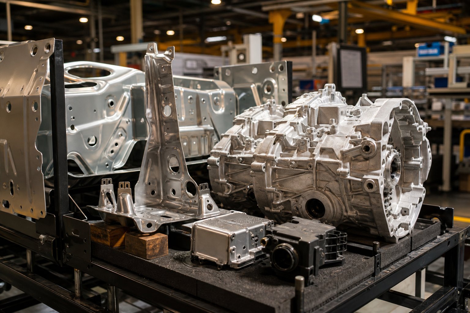
Walk through any car assembly plant and you'll notice a pattern. The body structure - roof panels, door inners, fender reinforcements, floor pans - is almost entirely stamped sheet metal. These parts share common traits: large surface area, shallow depth relative to footprint, uniform gauge thickness, and annual volumes in the hundreds of thousands. Metal forming and stamping dominate body-in-white production because progressive and transfer dies can stamp metal panels at rates no casting process matches.
Specific stamped automotive parts and why they stay in stamping territory:
- Structural B-pillar reinforcements - High-strength steel formed via hot stamping; requires grain-direction control and consistent wall thickness for crash energy absorption.
- EV battery enclosures - Large stamped aluminum sheet trays that need flatness, hermeticity at weld seams, and high-volume throughput to keep pace with battery pack assembly lines.
- Seat brackets and cross-members - Simple bent geometries produced at 300+ strokes per minute; no 3D complexity that would justify casting tooling.
- Brake dust shields - Thin stamped steel with multiple pierced holes; volumes exceed one million per year per vehicle platform.
Die casting occupies a different zone in the same vehicle. Wherever the geometry turns three-dimensional, integrates multiple functions into one part, or demands internal channels and bosses, casting takes over:
- Transmission housings - Complex internal ribbing, bearing bores, and oil passages that would require welding dozens of stamped pieces together.
- Engine blocks and cylinder heads - Internal water jackets and oil galleries impossible to achieve through any sheet metal process.
- Sensor and ECU housings - EMI shielding enclosures with integrated mounting bosses, connector pockets, and thermal management fins cast in a single shot.
- Structural mega-castings - Rear underbody sections consolidating 70+ stamped and welded parts into one aluminum casting, a trend pioneered for EV platforms.
Aerospace follows a similar logic. Stamped titanium and aluminum brackets dominate where flat profiles and light gauge suffice, while cast magnesium and aluminum serve housings, gearbox covers, and avionics enclosures requiring complex internal geometry.
Electronics and Consumer Goods Applications
Shrink the scale and the same principles hold. In electronics, stamped copper lead frames are the backbone of semiconductor packaging - millions of tiny copper alloy frames produced at high speed on progressive dies, connecting microchips to circuit boards in everything from smartphones to automotive ECUs. The process works because lead frames are essentially flat, require extreme dimensional precision, and run at volumes where stamping's speed advantage is unbeatable.
Other electronics and consumer parts where hardware stamping is the clear choice:
- RF shields and EMI cans - Thin stamped stainless or nickel-silver enclosures soldered onto PCBs; simple box geometry at massive volume.
- Battery contacts and spring clips - Stamped copper or beryllium-copper with precise spring geometry; rely on material grain properties for fatigue life.
- USB and connector shells - Progressive-die stamped and formed at thousands of parts per hour; dimensional consistency critical for mating interfaces.
Die casting claims electronics territory when parts need structural rigidity, thermal mass, or cosmetic surfaces across complex 3D shapes:
- Laptop and tablet chassis - Magnesium or aluminum die cast shells providing rigidity and heat spreading across thin, curved profiles.
- Heat sinks for LED lighting and power electronics - Fin arrays and integrated mounting features that stamping cannot produce in a single operation.
- Power tool housings - Die cast aluminum or magnesium bodies with ergonomic contours, threaded bosses, and motor mount features consolidated into one part.
- Camera and drone frames - Magnesium castings delivering minimum weight with maximum stiffness for handheld or airborne applications.
Here's what many engineers overlook: hybrid manufacturing, where both processes serve the same final assembly. Picture a stamped copper connector pin pressed into a die cast aluminum sensor housing. Or an automotive door module where a die cast structural carrier holds stamped steel reinforcement brackets and stamped copper bus bars. Neither process replaces the other - they complement each other within a single product. The stamped parts bring material-specific conductivity, spring properties, and in-plane precision. The cast parts bring three-dimensional integration and structural consolidation.
Recognizing these hybrid scenarios prevents a common sourcing trap: forcing an entire assembly into one process when splitting it across both yields lower total cost and better performance. The real decision framework isn't "stamping or casting" - it's "which features belong in which process, and how do the resulting parts come together?"
How to Choose Between Stamping and Die Casting for Your Project
You've seen the process mechanics, design constraints, cost curves, defect profiles, and real-world applications. The question that remains is practical: when you're staring at a new part design on your screen, how do you decide which process gets your tooling investment?
Forget abstract flowcharts. Think in terms of three real scenarios most engineers encounter repeatedly:
Scenario A: A mounting bracket. It's flat with two 90-degree bends, four pierced holes, made from 1.5 mm stamped steel sheet. Annual volume is 200,000 units. This part has no internal features, no bosses, no ribs - just bent geometry from a flat blank. The answer is stamping, every time. A progressive metal stamping die handles this at hundreds of strokes per minute, and the per-part cost will be a fraction of what casting would deliver.
Scenario B: An electronics enclosure. It has internal ribs for board mounting, integrated snap-fit features, thin walls with draft on all surfaces, and a cosmetic exterior. Annual volume is 30,000 units. This part's three-dimensional complexity - internal bosses, uniform thin walls, and consolidated features - makes die casting the natural fit. Trying to achieve this geometry through stamping sheet metal would require multiple stations, secondary welding, and assembly operations that eliminate any cycle-time advantage.
Scenario C: A connector housing. Moderate 3D geometry, 80,000 units per year, achievable through either a four-station die metal stamping setup or a single-cavity die cast mold. Both work technically. Here's where you compare total landed cost: stamping die plus secondary deburring and tapping versus casting mold with as-cast threads and minimal finishing. Run the numbers on both - including maintenance, scrap rate, and secondary ops - before committing capital.
The decision logic distills to three gates: geometry complexity, production volume, and total cost including secondary operations. If a part clears the first two gates pointing toward the same process, you have your answer. If both processes are technically feasible, the third gate - total landed cost - breaks the tie.
Decision Criteria Checklist for Engineers
Before you request quotes or commit to tooling, answer these questions. They'll prevent the most expensive mistake in metal-forming procurement: choosing your process based on habit or a single variable rather than the full picture.
- Part geometry complexity - Is the part flat or shallow-formed (bends, shallow draws), or does it require full 3D features like ribs, bosses, and internal cavities?
- Annual production volume - Are you above 50,000 units per year where stamping's speed advantage dominates, or in the 5,000–30,000 range where casting's single-operation simplicity may offset slower cycles?
- Material requirements - Do you need ferrous metals (steel, stainless) that rule out die casting? Or non-ferrous alloys (aluminum, zinc, magnesium) where both processes compete?
- Tolerance criticality - Are your tightest dimensions on flat, in-plane features (stamping advantage) or on complex 3D surfaces that require casting plus finish machining?
- Surface finish needs - Does the part need parent-material finish quality (stamping), or is a cast texture with secondary finishing acceptable?
- Secondary operations budget - How much post-processing does each route require? Tapping, deburring, plating, machining - these costs flip the economics faster than most buyers expect.
If your answers point consistently toward one process, your path is clear. If they split - some favoring stamping, others favoring casting - run a total-cost comparison across a minimum two-year production horizon before placing tooling orders.
When Stamping Dies Are the Better Investment
Certain project profiles make a custom metal stamping die the unambiguous winner. You'll recognize these patterns:
High-volume flat or shallow-formed parts. When annual quantities exceed 50,000 units and part geometry stays within bending, blanking, and moderate drawing territory, stamping's cycle-time advantage creates per-part economics that casting simply cannot match. Progressive dies running at 200–600+ strokes per minute produce finished components faster than any mold-filling process.
Parts requiring consistent flatness and dimensional stability. Stamped components maintain the flatness inherent to their parent sheet stock. If your assembly relies on datum surfaces that must mate flush without machining - think shielding panels, base plates, or heat spreader interfaces - stamping sheet metal preserves that surface integrity through the forming process.
Applications where material grain direction matters. Fatigue-critical components like spring contacts, structural reinforcements, and flex circuits depend on grain orientation for cycle life. Stamping preserves and leverages the rolling-direction grain structure of the parent coil, allowing engineers to orient bends perpendicular to grain for maximum ductility and fatigue resistance. Castings have no grain structure - their isotropic microstructure is an advantage in some contexts but a limitation when directional strength matters.
Ferrous material requirements. If your application demands carbon steel, stainless steel, or specialty high-strength alloys, die casting isn't an option. These materials are stamped exclusively in the high-volume forming world.
For engineers and buyers who've worked through this checklist and determined that stamping is their optimal process, the next step is sourcing tooling from a supplier with proven die engineering capability. YICHEN's custom stamping die services offer an entry point for projects requiring engineered metal-forming tooling - whether you need progressive dies for high-speed production, hot stamping dies for structural automotive components, or transfer tooling for deep-drawn geometries. Their in-house die design and manufacturing capability covers the full range of die stamping applications discussed throughout this article.
Selecting the right process is half the equation. The other half - finding a tooling supplier who can actually execute your die design at the quality level your production demands - requires its own set of evaluation criteria and procurement discipline.
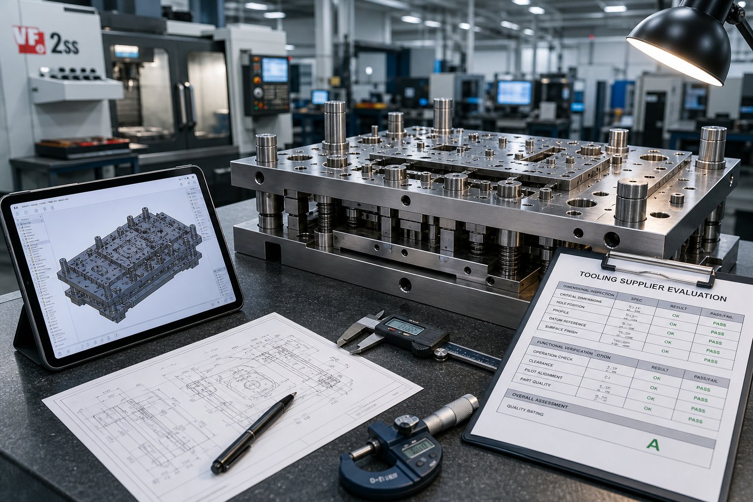
Sourcing Tooling and Evaluating Suppliers for Stamping and Casting Projects
You've identified your process, locked in the geometry, and confirmed the volume economics. The project lives or dies on what happens next: finding a tooling supplier who can translate your CAD file into a production-ready stamping mold or casting die - on time, on budget, and at the quality level your application demands.
This is where many procurement teams stumble. A vague request for quote gets a vague price back. Missing information triggers rounds of back-and-forth that add days or weeks to your timeline. And choosing a supplier based solely on the lowest bid often means discovering capability gaps after you've already committed tooling dollars. Here's how to avoid those traps.
What to Include in a Stamping or Casting RFQ
Think of your RFQ as the single document that determines quote accuracy. Manufacturing suppliers report that incomplete RFQs add one to two days of clarification emails per missing detail - and every assumption a supplier makes to fill gaps introduces pricing risk that lands on your side of the table. A complete RFQ gets you an accurate quote in 24 to 48 hours. An incomplete one gets you a padded estimate that protects the supplier, not you.
Whether you're sourcing a metal die stamp for progressive blanking or a multi-cavity casting mold, include these essentials:
- 3D CAD model (STEP or IGES) plus a dimensioned 2D PDF - The CAD file lets the supplier analyze geometry for manufacturability. The PDF drawing calls out what matters: critical dimensions, GD&T datums, and notes that don't transfer in a neutral file format. A blurry photo or verbal description is not acceptable for tooling quotes.
- Material grade specification - "Aluminum" is not a spec. State the exact alloy and temper: 5052-H32 for a stamped bracket, A380 for a die casting, 1008 CRS for a stamped steel clip. If you're unsure, describe the operating environment and let the supplier recommend - but include that conversation in the RFQ rather than leaving it blank.
- Annual volume projection and order pattern - A stamp die cutter designed for 50,000 parts per year uses different steel grades and construction methods than one built for 5 million cycles. State your immediate quantity, expected annual volume, and whether demand is steady or seasonal. This single data point drives tooling material selection, cavity count decisions, and amortization calculations.
- Critical dimensions and tolerances - Mark which features are functionally critical versus general tolerance. Tighter callouts cost more - a ±0.05 mm bore requires different tooling precision than a ±0.3 mm non-critical edge. Suppliers price to your tightest tolerance, so don't over-specify features that don't need it.
- Surface finish requirements - Specify Ra values for critical surfaces, or state "standard as-stamped" or "as-cast" if cosmetic finish isn't required. If the part receives plating, powder coating, or anodizing downstream, note that - it affects how the supplier approaches burr control and surface preparation.
- Secondary operation needs - Tapping, deburring, heat treatment, plating, assembly - anything beyond the primary forming operation. These details affect whether the supplier quotes the complete landed part or just the stamping/casting step, and they influence tooling design decisions like integrating in-die tapping or designing for minimal post-processing.
- Delivery timeline and shipping terms - State a concrete date or lead-time requirement. "As soon as possible" tells the supplier nothing. "First samples in 6 weeks, production tooling validated by week 10" gives them a schedule to commit to or push back on honestly.
One detail that separates experienced buyers from novices: include the application context. Telling your supplier "this bracket mounts an EV battery module and sees vibration loading" immediately flags material and tolerance considerations they might otherwise miss. Practical RFQ guidance from experienced manufacturers consistently emphasizes that application context helps suppliers catch potential design problems before tooling cuts begin - saving revision cycles and cost downstream.
Evaluating Tooling Suppliers and Lead Times
A complete RFQ attracts accurate quotes. But an accurate quote from an incapable supplier still ends in disaster. Evaluating a stamping mold or casting die vendor requires looking beyond price into operational capability, quality infrastructure, and scalability.
Here's what to assess - and the red flags that should trigger caution:
In-house die design capability. Suppliers who design and build tooling under one roof iterate faster, maintain tighter integration between design intent and manufacturing reality, and own problems without finger-pointing between a design house and a separate fabrication shop. Ask whether they use simulation software (forming analysis for stamping, flow simulation for casting) to validate tooling before cutting steel. If die design is outsourced, understand who owns the design IP and how revision cycles are managed.
Material certifications and traceability. Supplier evaluation frameworks consistently identify material traceability as a non-negotiable criterion. Your supplier should provide mill certifications for both the tooling steel (D2, A2, H13, or carbide inserts) and the production material they'll run through the die. In regulated industries - automotive (IATF 16949), aerospace (AS9100), medical - these certifications aren't optional; they're audit requirements.
Quality management system. ISO 9001 certification is a baseline indicator that the supplier has documented processes for design control, in-process inspection, and corrective action. For automotive stamping, look for IATF 16949 compliance. Beyond the certificate, ask about their SPC implementation, calibration schedules for inspection equipment, and defect tracking systems. A supplier using statistical process control to monitor stamping production catches dimensional drift before it becomes a batch rejection.
Prototype and sample availability. Can they produce soft-tool prototypes or first-article samples before committing to hardened production tooling? This capability reduces risk dramatically - you validate fit, function, and assembly before spending $50,000+ on a hardened progressive die. Suppliers who skip this step or can't offer it are asking you to gamble on first-shot success.
Production scalability. Your initial order might be 20,000 parts per year, but if demand grows to 200,000, can the supplier scale? Assess their press tonnage range, available machine hours, workforce depth, and willingness to build duplicate tooling for multi-press production. A supplier with moderate current capacity but demonstrated agility often outperforms a larger facility with rigid scheduling and long lead-time queues.
Red flags to watch for:
- Quoting without asking technical questions about your part - indicates they're pricing blind rather than engineering a solution.
- No willingness to share sample inspection reports or PPAP documentation from previous projects.
- Lead times quoted without qualification - experienced suppliers distinguish between design completion, tool fabrication, sampling, and production-ready delivery milestones.
- Pricing dramatically below market without clear explanation - usually signals corners cut in tool steel quality, heat treatment, or finish grinding that shorten die life.
For buyers who've worked through this evaluation process and determined that a custom stamping die is their path forward, YICHEN represents a concrete starting point. Their engineering team covers progressive, transfer, and hot stamping die design with in-house fabrication - relevant for projects ranging from high-volume automotive brackets to precision metal die stamp tooling for electronics. They're one qualified option among the criteria discussed here, but their combination of custom die engineering and production-scale manufacturing capability makes them a practical resource for buyers entering the sourcing phase with a clear spec in hand.
Procurement in stamping die casting projects isn't just about finding the cheapest quote. It's about matching your technical requirements to a supplier whose capabilities, quality systems, and production capacity align with your project's full lifecycle - from first prototype through year-five maintenance and resharpening. Get the RFQ right, evaluate against substance rather than price alone, and the tooling investment that follows will deliver returns across millions of production cycles.
Stamping Die Casting: Frequently Asked Questions
1. What is the main difference between stamping and die casting?
Stamping is a cold-forming process that uses mechanical force to reshape solid sheet metal into parts through punches and dies. Die casting is a hot-forming process that injects molten metal (typically aluminum, zinc, or magnesium) into a reusable steel mold under high pressure. The fundamental distinction is that stamping reshapes solid material while die casting solidifies liquid metal. This difference drives all downstream decisions about tooling, materials, achievable geometries, and per-part cost structures.
2. Can steel be die cast?
Steel cannot be die cast using conventional equipment. Steel melts between 1,370 and 1,530 degrees Celsius, temperatures that would rapidly destroy even hardened tool-steel molds. According to industry data, 95% of die cast parts use non-ferrous metals like aluminum, zinc, and magnesium. Steel parts requiring mold-based production are typically made through investment casting or sand casting, where expendable molds tolerate extreme heat. For high-volume steel components with flat or shallow geometry, metal stamping using progressive or transfer dies is the standard production method.
3. When should I choose stamping over die casting for my parts?
Stamping is the better investment when your parts are flat or shallow-formed (bends, blanks, moderate draws), annual volumes exceed 50,000 units, you need ferrous materials like carbon steel or stainless steel, or your tightest tolerances are on in-plane features. Stamping also wins when material grain direction matters for fatigue life, or when consistent flatness is required for mating surfaces. Suppliers like YICHEN (yichen-group.com/stamping-die/) offer custom stamping die engineering for progressive, transfer, and hot stamping applications across these scenarios.
4. What information should I include in a stamping or die casting RFQ?
A complete RFQ should include a 3D CAD model (STEP or IGES) with a dimensioned 2D PDF, exact material grade and temper specification, annual volume projection with order pattern, critical dimensions marked with specific tolerances, surface finish requirements with Ra values, secondary operation needs (tapping, plating, heat treatment), and a concrete delivery timeline. Including application context helps suppliers identify potential design issues before tooling begins. Incomplete RFQs typically add one to two days of clarification per missing detail and result in padded pricing that protects the supplier rather than the buyer.
5. What are the most common defects in stamping and die casting?
Stamping defects relate to mechanical force: springback (elastic recovery after forming), wrinkling (insufficient blank holder force), tearing (strain exceeding material limits), and burrs (worn punch edges or incorrect clearance). Die casting defects relate to thermal behavior: gas porosity (trapped air during injection), shrinkage cavities (uneven solidification), cold shuts (metal fronts failing to fuse), and flash (excess metal at parting lines). Each process requires different inspection methods. Stamped parts use SPC charting and CMM verification, while cast parts need X-ray inspection and pressure testing to detect internal porosity.


