


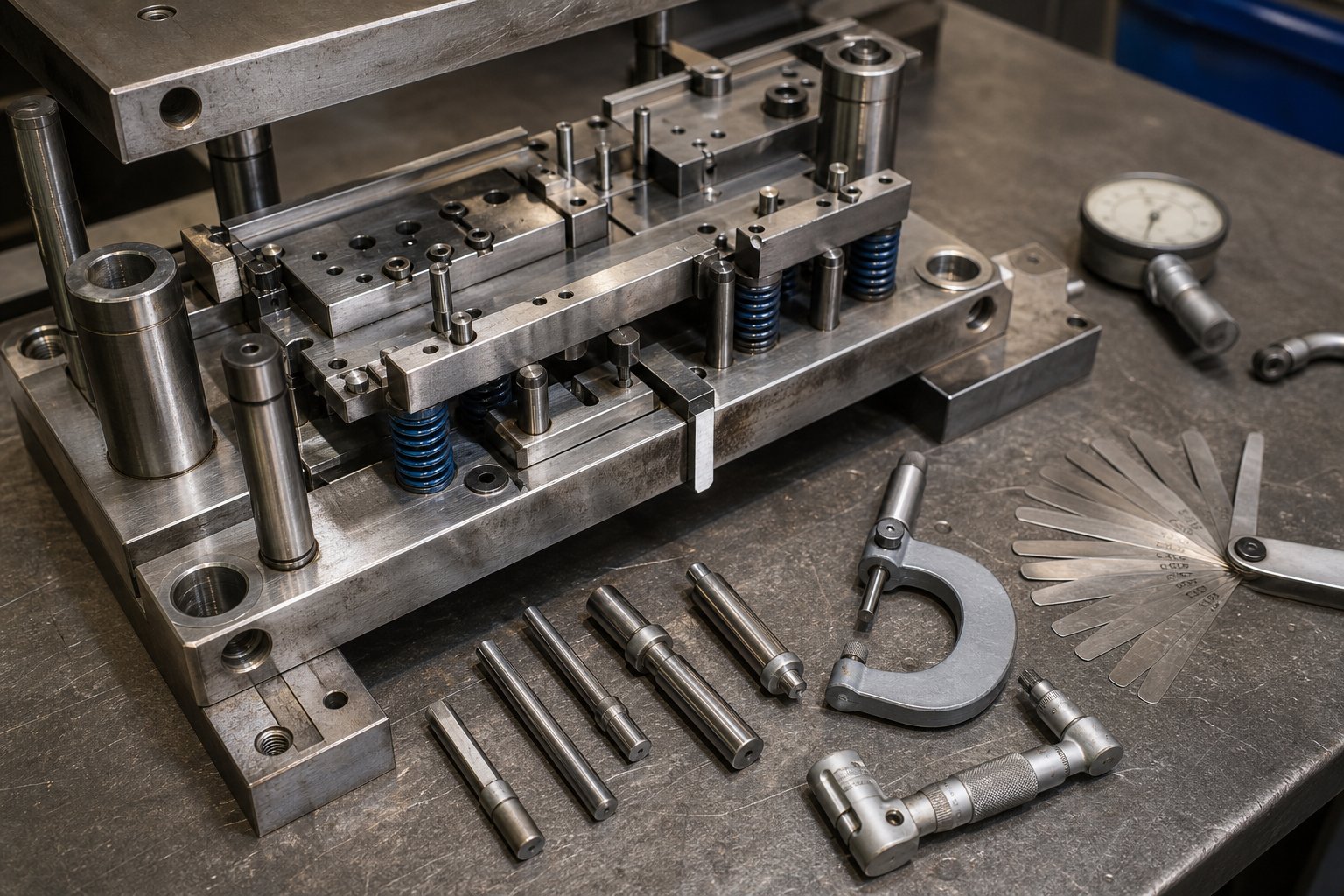
Why a Structured Maintenance Checklist Extends Die Life
A stamping die maintenance checklist is a documented sequence of inspections, measurements, and corrective actions performed on a die at defined intervals to preserve its cutting geometry, alignment, and production capability. It sounds straightforward. Yet this single document is the difference between a die that runs hundreds of thousands of reliable strokes and one that cracks a punch halfway through a Tuesday afternoon production run.
What a Stamping Die Maintenance Checklist Actually Covers
Think of the checklist as four layers of attention mapped to the die's operational cycle. Pre-run checks confirm the die is safe to load and dimensionally correct. In-run checks monitor part quality and strip progression while the press is cycling. Post-run procedures capture end-of-job condition and flag emerging wear. Scheduled teardowns strip the die to individual components for measurement, sharpening, and replacement. Each layer catches issues the others miss, and skipping any one of them leaves a blind spot where small problems compound into expensive failures.
When structured properly, the checklist also functions as a diagnostic tool. Every measurement recorded, every burr height noted, and every spring length logged builds a wear history that reveals patterns over time. That history tells you not just what to fix today, but what will fail next month.
Why Most Shops Operate Without One
Here is the uncomfortable truth: most press shops still rely on tribal knowledge passed between die technicians through word of mouth. The veteran toolmaker knows that Die #47 needs its pilots checked every 30,000 hits because of the tight tolerance on that second-station pierce. But when that technician retires or moves to a different shift, the knowledge walks out the door. Maintenance quality becomes inconsistent, and unplanned downtime creeps upward.
A preventive maintenance framework built around structured procedures replaces guesswork with repeatable discipline. It ensures every technician, regardless of experience level, performs the same critical checks in the same sequence.
Die wear is driven by stroke count, not calendar time. A die sitting on the shelf for six months needs different attention than one that just ran 150,000 hits. Effective maintenance intervals are always anchored to production cycles first and supplemented by time-based triggers only for idle tooling.
This operational-cycle framework, organized around what happens before, during, after, and between production runs, forms the backbone of everything that follows. Each phase demands specific inspections, specific tools, and specific personnel. The gap between shops that control die life and shops that constantly react to die failures almost always traces back to whether these phases are documented or left to memory.
In-Press Quick Checks Versus Off-Press Teardown Procedures
Most stamping operations treat maintenance as one activity. In reality, it splits into two fundamentally different workflows: what the operator does while the die is running in the press, and what the die technician does after the die is pulled and placed on the bench. Confusing these two categories, or worse, skipping the first and overloading the second, is where maintenance programs break down.
In-Press Quick Checks During Production Runs
Imagine you are an operator monitoring a progressive die cycling at 60 strokes per minute. Your stamping die operator inspection during production focuses on sensory cues and quick sampling rather than disassembly. You are watching for visual slug buildup in the scrap chute, listening for abnormal popping or grinding sounds that indicate a punch contacting a stripper plate incorrectly, and verifying that the strip feeds cleanly without hesitation at each progression. At fixed intervals, typically every 500 to 1,000 parts, you pull a sample and check critical dimensions, burr height, and hole quality against the part print.
These in-press die inspection checks for operators require no special tooling beyond a caliper, a burr gauge, and trained attention. Their purpose is early detection. A slug sitting on the die face will damage the next hit. A feed misalignment will snowball into scrap within seconds. Catching these signals in real time prevents cascading failures that turn a minor adjustment into a major repair.
Off-Press Teardown Inspection Procedures
Off-press die teardown procedure steps begin only after the die is safely removed from the press, cleaned of lubricant and debris, and placed on a stable workbench. A die technician then performs full disassembly: pulling punches, removing stripper plates, extracting pilots, and separating upper and lower die halves. Each component is inspected individually for wear, measured against baseline dimensions, sharpened if needed, and replaced when beyond tolerance.
For progressive dies, teardown sequence matters. The progressive die teardown sequence must follow station order, from the first pierce or blank station through to the final cutoff, so that strip progression integrity is preserved during reassembly. Mixing station components or reassembling out of order risks misalignment that only shows up as defective parts once the die is back in the press. Experienced toolmakers recommend saving the last strip from a production run as a reference map when sequencing teardown and rebuilding each station.
| Task Type | Who Performs It | Frequency Trigger | Tools Required |
|---|---|---|---|
| Visual slug and scrap inspection | Press operator | Every 15-30 minutes during run | Flashlight, mirror |
| Part sampling and dimensional check | Press operator | Every 500-1,000 strokes | Caliper, burr gauge, part print |
| Listening for abnormal press sounds | Press operator | Continuous during run | None (trained ear) |
| Strip feed progression monitoring | Press operator | Continuous during run | Visual observation |
| Full die disassembly and cleaning | Die technician | Stroke-count interval or end of job | Hand tools, press, solvent tank |
| Component measurement and inspection | Die technician | Each teardown cycle | Micrometers, pin gauges, height gauge |
| Punch and die section sharpening | Die technician | When burr height exceeds spec | Surface grinder, parallels |
| Spring and pilot replacement | Die technician | When measured beyond tolerance | Calipers, replacement components |
The distinction is simple but critical: operators detect problems, technicians solve them. A well-built stamping die maintenance checklist assigns clear ownership at each level so nothing falls into the gap between production and the toolroom. When both layers function together, emerging wear gets flagged during production and corrected during the next scheduled teardown, long before it causes unplanned downtime or scrap spikes.
Of course, knowing when to perform each type of check is only half the equation. The other half is knowing exactly what to look for on every individual component once that die lands on the bench.
Component-by-Component Maintenance Breakdown
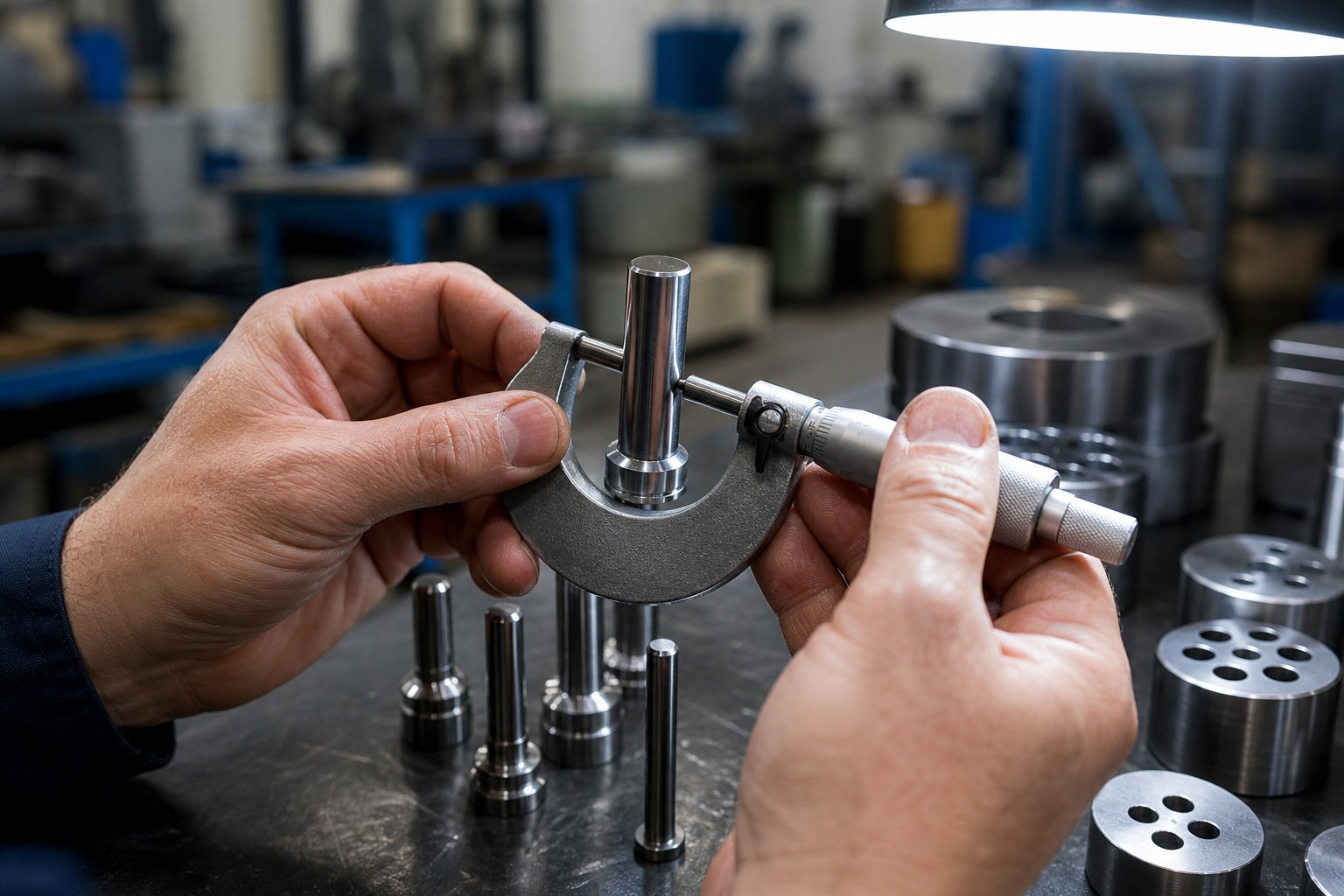
A die is not one thing. It is dozens of individual components working in precise coordination, and each one wears differently, fails differently, and demands its own inspection criteria. Generic checklists that say "inspect die condition" miss the point entirely. You need to know what to measure on each part, what the acceptable limits are, and when a component has crossed the line from serviceable to replacement-ready. Here is where that level of detail lives.
Cutting Components and Edge Inspection
Cutting components do the most violent work in any stamping die. Punches slam through material at high speed, and die sections receive that force on every stroke. Understanding how to inspect die cutting edges for wear starts with knowing the three failure modes: chipping (small pieces breaking from the edge), mushrooming (the top of the punch deforming from repeated impact), and edge rollover (the cutting edge dulling into a radius rather than staying sharp).
- Examine each punch under magnification for micro-chipping along the cutting edge. Any visible chip wider than 0.1 mm warrants sharpening or replacement.
- Check punch heads for mushrooming. A raised lip on the struck end indicates the punch is absorbing excess impact and needs redressing.
- Measure burr height on the last parts produced. Burrs exceeding 10% of material thickness typically signal that cutting clearance has degraded or edges need sharpening.
- Inspect die button cutting edges for scoring marks, slug buildup, or edge breakdown. Verify slug retention features such as angular relief or back-taper are intact.
- Confirm punch-to-die clearance using feeler gauges or test cuts. Proper clearance runs between 5% and 12% of material thickness per side, depending on material type and hardness.
Stamping die punch inspection criteria should always reference the specific material being processed. A clearance that works perfectly for cold-rolled steel will produce excessive burrs on aluminum and premature edge failure on stainless.
Guidance and Stripping System Checks
Guidance and stripping systems keep everything aligned and ensure parts and scrap eject cleanly. When these systems wear, the damage cascades into cutting components, creating secondary failures that look unrelated unless you trace them back to the source.
- Perform guide pin and bushing wear measurement by checking for vertical play. Insert the guide pin into its bushing and feel for lateral movement. Any detectable looseness beyond the original fit class tolerance requires bushing replacement.
- Inspect guide pin surfaces for scoring, galling, or discoloration from heat buildup. Vertical score lines indicate debris contamination or insufficient lubrication.
- Verify pilot pin diameters with a micrometer against their nominal dimension. Pilots worn more than 0.01 mm undersize can no longer hold strip registration accurately.
- Conduct a stripper plate flatness inspection procedure by placing the stripper face-down on a precision surface plate and checking with a feeler gauge. Deviation beyond 0.03 mm across the plate length requires resurfacing.
- Test stripper spring pressure by compressing the assembly and verifying uniform return force. Uneven stripping causes parts to tilt during ejection and damages adjacent punches.
Heel blocks deserve equal attention. These components absorb lateral thrust during cutting operations. Inspect wear surfaces for galling or material transfer, and verify that the heel block-to-heel contact area has not worn into a groove that allows lateral die shift under load.
Springs and Fastener Verification
Springs are the most commonly ignored wear item in a stamping die, mostly because they still "work" right up until the moment they break. A die spring free length tolerance check catches degradation before failure occurs.
- Measure each spring's free length with a caliper and compare against its original specification. Industry practice flags springs for replacement when free length has decreased by more than 10% from nominal, a threshold consistent with DIN 2095 tolerance guidance for compression springs.
- Inspect for cracks, corrosion, or set marks on coil surfaces. Any visible fracture means immediate replacement regardless of length measurement.
- Verify that springs are seated squarely in their pockets without cocking or interference from debris.
- Check all socket head cap screws for proper torque using a calibrated torque wrench. Loose fasteners allow die sections to shift under stamping load.
- Inspect screw threads for stripping, cross-threading, or elongation. Replace any fastener that does not engage with normal resistance.
- Confirm all dowel pins are fully seated and undamaged. A dowel that has backed out even partially compromises the alignment it was designed to hold.
Every measurement and observation from this component-level inspection belongs on the die's maintenance card. Recording actual values rather than simple pass/fail marks creates the wear trend data you need to predict when a component will reach its limit, not just react after it already has. That predictive capability depends on one more variable: how often you perform these inspections in the first place.
Stroke-Count and Calendar-Based Maintenance Intervals
Knowing what to inspect on each component is essential, but frequency determines whether you catch wear before it causes failures or after. The question of how often to service stamping dies has a deceptively simple answer: let the die tell you, measured in strokes rather than days on the calendar.
A die that sits idle on a rack for three months does not wear. A die that runs 200,000 hits in a single week does. Calendar-based scheduling alone, such as "service every 30 days," ignores this reality. It leads to over-maintenance on low-volume tooling and under-maintenance on high-volume dies that accumulate wear far faster than the calendar suggests. The most reliable stroke count based die maintenance schedule uses production cycles as the primary trigger and reserves calendar intervals only for idle dies that need corrosion checks and lubrication refreshes.
Stroke-Count Triggers for Each Maintenance Level
A tiered preventive maintenance structure for progressive dies and transfer tooling assigns escalating levels of intervention based on cumulative stroke count. Each level increases in scope, skill requirement, and time investment.
| Maintenance Level | Typical Stroke-Count Trigger | Tasks Performed | Personnel Responsible |
|---|---|---|---|
| Level 1: Production Run Check | Every run (continuous) | Visual slug inspection, part sampling, sound monitoring, strip feed verification, lubrication confirmation | Press operator |
| Level 2: Technician Inspection | 10,000 - 50,000 strokes | Die removal, cleaning, visual inspection of cutting edges and guidance systems, measurement of critical wear points, spring length verification, minor adjustments | Die maintenance technician |
| Level 3: Full Teardown and Reconditioning | 100,000 - 500,000 strokes | Complete disassembly, all component measurement, sharpening of cutting edges, spring and pilot replacement, clearance restoration, full reassembly and validation | Senior die technician / toolmaker |
These ranges are starting points, not fixed rules. A simple blanking die running mild steel might stretch Level 2 intervals to 50,000 strokes comfortably. A complex progressive die with 20 stations punching stainless steel might need Level 2 attention every 10,000 to 15,000 strokes. The table provides a framework; your wear data refines it.
Adjusting Intervals by Material and Die Complexity
Three variables shift maintenance intervals significantly:
- Material hardness and abrasiveness. High-strength steel, stainless, and silicon steel accelerate edge wear. A die maintenance interval by material thickness must account for both: thicker gauges impose higher cutting forces, while harder alloys abrade edges faster. Expect to halve your baseline intervals when switching from cold-rolled steel to stainless or high-strength low-alloy grades.
- Die complexity. A single-station die has fewer failure points than a 30-station progressive die with cams, lifters, and aerial bends. More stations mean more components wearing simultaneously, and a failure at any one station can cascade into adjacent stations before detection.
- Production speed. Higher strokes per minute generate more heat and reduce the time lubricant has to recoat surfaces between hits. Faster runs compress the effective life between maintenance events even when the stroke count remains the same.
For a new die entering production without historical data, start conservative. Set Level 2 at the lower end of the range and Level 3 at roughly five times that interval. Run the first several maintenance cycles with detailed measurement records, then compare actual wear rates against your initial assumptions. If components show minimal wear at the Level 2 trigger, extend the interval by 10-20% for the next cycle. If you find unexpected edge breakdown or spring fatigue, tighten the schedule accordingly.
This iterative refinement, guided by real measurements rather than guesswork, is what separates a living maintenance program from a static document that nobody trusts. Over three to five maintenance cycles, your intervals will converge on the die's true wear behavior, and the schedule becomes predictive rather than reactive.
Schedule preventive overhauls at roughly 70-80% of a die's expected life between major services to avoid mid-run failures that halt production without warning.
Interval discipline keeps components within serviceable limits. But the single maintenance action that most directly restores cutting performance, sharpening, carries its own set of criteria that determine whether the die returns to production or reaches its engineering end-of-life.
Grinding Criteria and the Sharpen Versus Replace Decision
Sharpening is the single maintenance action that most directly restores a die's ability to produce clean parts. But grinding too little leaves dull edges in service. Grinding too much shortens the die's total life and risks thermal damage that weakens the tool steel from the inside out. Knowing exactly when to sharpen stamping die cutting edges, how much material to remove, and when a component has reached its limit separates disciplined maintenance from expensive guesswork.
When to Sharpen Based on Measurable Edge Condition
You do not sharpen on a calendar. You sharpen based on what the edge and the parts are telling you. Burr height measurement for die maintenance is the most reliable trigger because it gives you a number rather than a subjective opinion. When burr height on stamped parts exceeds 10% of material thickness, the cutting edges have worn enough to require attention. Waiting longer only forces you to remove more material during sharpening, which shortens die life unnecessarily.
Visual inspection supports the measurement. Look at the cutting edge under magnification. A sharp edge shows a clean, defined line where the face meets the relief angle. A worn edge shows a visible radius, often described as a "land" that reflects light when tilted. Industry guidelines recommend sharpening when this worn radius reaches 0.010 inch (0.25 mm). At that threshold, a light touch-up restores the edge with minimal material removal. Waiting until the radius grows larger forces heavier grinding passes that generate more heat and consume more of the punch's usable length.
Other signals that confirm sharpening is due:
- Increased press tonnage or louder-than-normal cutting sounds during production
- Parts showing excessive rollover on the burnish side of pierced holes
- Slug pulling or slugs sticking to punch faces, indicating insufficient shear break
- Visible chipping along the cutting edge that has not yet progressed into the body of the punch
Frequent light sharpening outperforms infrequent heavy grinding every time. Tools last longer, cut cleaner, require less press force, and produce more consistent part quality between services.
The Sequential Grinding Procedure
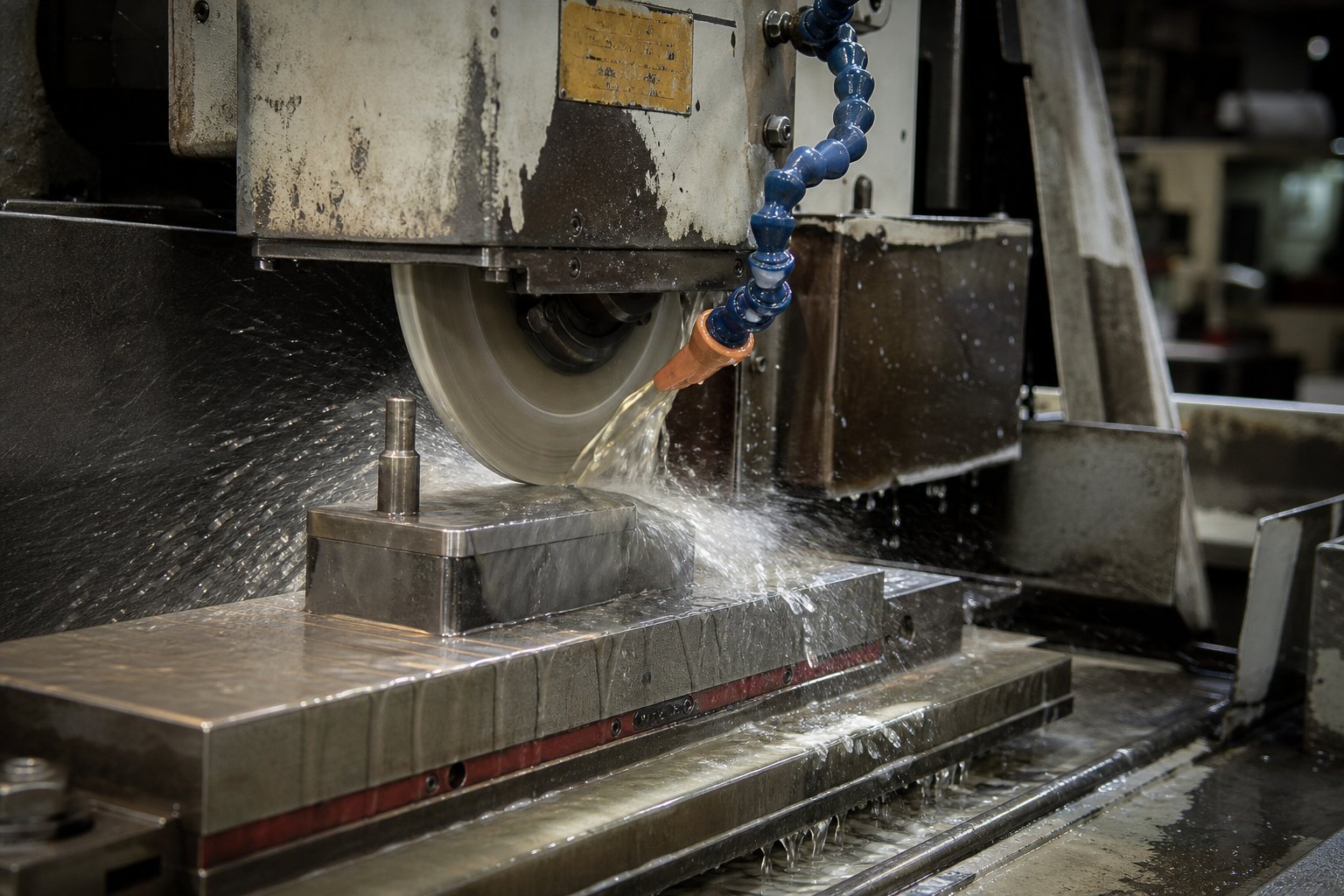
Surface grinders are the backbone of any die maintenance shop for good reason. They provide controlled, repeatable material removal that hand grinding simply cannot replicate. Attempting to sharpen punches with a hand grinder while the die sits in the press might save time in the moment, but it is nearly impossible to control feed rate, maintain flatness, or prevent localized overheating. A proper surface grinder with flood coolant ensures consistent results every pass.
Here is the procedure that protects both the edge and the tool steel behind it:
- Clamp the punch squarely in a V-block on the magnetic chuck of the surface grinder. Verify it sits flat and parallel to the wheel traverse direction.
- Dress the grinding wheel using a single-point or multi-point diamond dresser with a downfeed of 0.0002 to 0.0008 inch (0.005 to 0.020 mm) and a quick crossfeed of 20-30 inches per minute.
- Select a standard vitrified-bond aluminum oxide wheel in the hardness range of D to J with a grain size of 46 to 60. For nitride-coated punches, shift toward the finer end of the range.
- Apply flood coolant directly at the contact zone between wheel and workpiece. Insufficient coolant is the primary cause of thermal damage during sharpening.
- Remove material in passes of only 0.001 to 0.002 inch (0.03 to 0.05 mm) per downfeed. Total material removal for a standard touch-up is typically 0.005 to 0.010 inch (0.13 to 0.25 mm). These die sharpening material removal limits prevent heat buildup that degrades hardness below the surface.
- After grinding, lightly stone the freshly sharpened edges with an India oil stone to leave a 0.001 to 0.002 inch (0.03 to 0.05 mm) radius. This micro-radius distributes cutting stress and prevents the flaking that causes rapid re-dulling.
- Demagnetize the punch completely and apply a light corrosion-preventive oil before returning it to storage or the die.
Thermal damage deserves special emphasis. Research into grinding damage shows that excessive heat causes the outer surface of hardened tool steel to expand faster than the cooler core, creating internal stresses. As the part cools, the surface softens, reducing wear resistance. In severe cases, discoloration, surface cracks, or a "fish scale" pattern appear. Dark discoloration indicates damage that extends below the visible surface and cannot be corrected by simply grinding deeper. That component needs replacement.
Sharpen Versus Replace Decision Framework
Every punch and die section has a finite amount of material available for sharpening. The sharpen versus replace die punch decision comes down to three measurable factors:
- Total cumulative material removed. Each sharpening reduces the punch's working length or the die section's thickness. Track the total amount ground away over the component's life. When cumulative removal approaches the engineering limit specified on the die design, replacement is required regardless of current edge condition.
- Remaining cutting land length. Punches need a minimum length below the punch holder to maintain proper engagement with strippers, pilots, and the die opening. Once sharpening shortens the punch beyond this functional threshold, it can no longer perform reliably.
- Evidence of subsurface damage. If a punch chips repeatedly after sharpening, or if discoloration appeared during a previous grinding cycle, the tool steel may have suffered internal heat damage that compromises its full cross-section. Further sharpening will not restore performance.
For die sections and matrices, the same logic applies but on a slower timeline. Because the matrix wears at roughly one-half to one-third the rate of the mating punch, it requires sharpening less frequently. When the die section is sharpened, verify thickness afterward and add shims to maintain proper shut height.
Progressive dies add one more constraint: all cutting stations must maintain uniform shut height after sharpening. If one station is ground while others are not, the sharpened station sits higher relative to the strip, changing its cutting engagement. Best practice is to sharpen all cutting punches and sections in a progressive die simultaneously, or to shim individual stations precisely to restore uniform height across the full strip progression.
This discipline keeps every station cutting at the correct depth and prevents the subtle dimensional drift that shows up as inconsistent part quality across different stations. It also preserves the strip's feed-line geometry so that pilots engage cleanly and carriers maintain their structural integrity through the final cutoff.
Sharpening restores what wear takes away. But when a stamped part shows defects despite freshly ground edges, the root cause often lies elsewhere in the die. Connecting specific quality problems back to their true maintenance source is where a checklist becomes a diagnostic tool rather than just a schedule.
Troubleshooting Part Defects to Root-Cause Maintenance Failures
A stamped part with a burr on it is not just a quality reject. It is a message from the die telling you exactly which component needs attention. Most stamping die defect troubleshooting guides stop at identifying the defect. The real value comes from mapping that defect backward through the die to a specific maintenance action, turning your checklist from a passive schedule into an active diagnostic tool.
Mapping Part Defects to Maintenance Root Causes
Every recurring part defect traces back to a specific component failure inside the die. Burrs, for example, are the most common signal. The burr caused by die wear root cause is almost always dull cutting edges or punch-to-die clearance that has opened beyond specification. Worn punches and incorrect die clearance remain the top contributors, but poor tool alignment and material thickness variation compound the issue.
Slug pulling follows a similar pattern. When a slug adheres to the punch face during withdrawal instead of dropping through the die opening, you are looking at vacuum effects between the flat punch face and the slug, combined with worn edges that no longer produce a clean shear break. Progressive die failure analysis confirms that increased burr formation raises stripping resistance, which in turn causes slugs to cling to punch surfaces. The slug pulling die maintenance fix involves sharpening the cutting edge to restore clean fracture, adding vacuum-relief features or air-blow systems, and verifying that die buttons still have proper angular relief for slug passage.
Misfeeds and strip hesitation point toward pilot wear or feed-line instability. Pilots worn even 0.01 mm undersize lose their ability to register the strip accurately, causing cumulative positional drift across progressive stations. Short hits, where the punch does not fully separate material, suggest shut-height drift or press timing issues that prevent full punch penetration. Wrinkles in formed areas reveal insufficient blank-holder pressure from worn or fatigued pressure pads. Splits and tearing at draw radii indicate that the forming radius has deteriorated through erosion or galling, concentrating strain beyond the material's forming limit.
Here is the stamping part quality defect to die maintenance mapping laid out as a diagnostic reference:
| Defect Observed | Probable Die Component Failure | Inspection Action | Corrective Maintenance Step |
|---|---|---|---|
| Excessive burrs on cut edges | Dull punch or die cutting edges; clearance opened beyond spec | Measure burr height; check punch-to-die clearance with feeler gauge | Sharpen cutting edges; restore clearance by replacing worn die buttons |
| Slug pulling (slugs on strip or die face) | Worn punch edges; vacuum adhesion; insufficient slug retention in die button | Inspect punch face flatness; verify die button relief angle and back-taper | Sharpen punch; add air-blow or vacuum relief; restore die button geometry |
| Misfeeds or strip registration errors | Worn pilot pins; feed-line wear; guide rail degradation | Measure pilot diameters; check strip guide clearance; verify feed progression | Replace pilots; adjust or replace strip guides; recalibrate feeder |
| Short hits (incomplete cuts) | Shut-height drift; press timing error; punch length lost to repeated sharpening | Verify shut height with gauge blocks; check punch working length against minimum | Reshim die to restore shut height; replace over-shortened punches |
| Wrinkles in formed areas | Pressure pad springs fatigued; blank-holder surface worn | Measure spring free lengths; inspect pad contact surfaces for wear patterns | Replace springs; resurface or replace pressure pads |
| Splits or tearing at draw radii | Draw radius eroded or galled; surface roughness increased | Inspect radius profile with radius gauge; check surface finish visually and by touch | Polish or re-radius draw edges; replace inserts if beyond rework limits |
Using Quality Feedback to Prioritize Maintenance Tasks
This mapping transforms how you use the checklist during every maintenance cycle. Instead of working through inspections in a fixed sequence regardless of what is actually happening in production, you lead with the defects the operator documented during the last run. If the production log shows burr height climbing over the last 5,000 strokes, the technician goes straight to cutting edges first. If slug pulling was flagged, the focus shifts to punch faces and die button relief.
Quality feedback creates a priority filter. It tells you which components are actively degrading right now versus which ones can wait until the next scheduled service. This is especially valuable during time-constrained maintenance windows where the die must return to the press quickly. Rather than performing every check at equal depth, you concentrate effort where the die is actually signaling distress.
In-die sensing technology reinforces this approach. Stripper-level sensors can detect slug pulling within a single stroke by identifying when the stripper plate fails to close to its proper depth. Force-monitoring sensors track punch sharpness in real time by measuring cutting load trends. These signals feed directly into your maintenance priority list, flagging components that need attention before the next scheduled teardown even arrives.
The diagnostic approach also builds institutional knowledge. When technicians consistently record which defect triggered which corrective action and how many strokes the fix lasted, you create a failure-history database for each die. Over time, patterns emerge. You might discover that Die #112 always develops slug pulling at station 4 around 35,000 strokes because of the small-diameter punch and tight slug clearance at that station. That insight becomes a proactive trigger rather than a reactive repair, and it informs decisions about which components to keep on hand for the next service cycle.
Spare Parts Inventory and Replacement Triggers
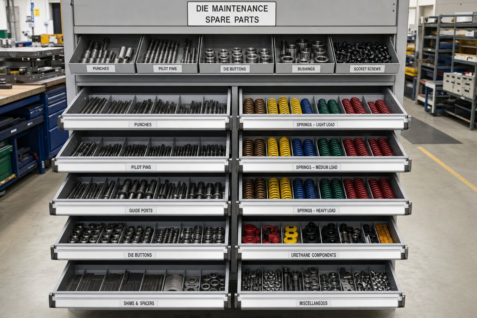
Diagnosing a failure means nothing if the replacement part is not on the shelf when you need it. A technician who identifies a worn pilot during a scheduled teardown but has to wait two weeks for a supplier to ship one has just converted a planned maintenance event into unplanned downtime on the next production run. Knowing which die wear parts to keep in stock, and how many, is the inventory discipline that separates shops running smooth schedules from shops constantly expediting emergency orders.
Critical Spare Components to Stock by Priority
Not every die component wears at the same rate or carries the same lead time risk. Your stamping die spare parts inventory list should be ranked by a simple formula: how fast does it wear multiplied by how long does it take to get a new one. Components that wear quickly and require custom manufacturing sit at the top. Off-the-shelf fasteners that wear slowly sit at the bottom.
- Punches (custom profiles): Highest wear rate of any component. Stock at least one full replacement set per die for high-volume tooling. Replacement trigger: cumulative sharpening depth reaches 70% of engineering limit, or edge chipping recurs within 5,000 strokes of the last grind.
- Die buttons and sections: Wear at roughly one-third the rate of punches but carry longer lead times for custom geometries. Stock one spare per critical station. Replacement trigger: clearance measured at maximum allowable despite re-sharpening, or slug retention features degraded beyond rework.
- Springs: Predictive replacement for stamping die springs relies on free-length tracking. Stock a full set per die. Replacement trigger: free length has decreased 10% from nominal, or spring has completed more than 1 million compression cycles.
- Pilot pins: Small diameter pilots wear fastest due to strip registration forces. Stock two to three spares per die. Replacement trigger: diameter worn 0.01 mm or more undersize.
- Guide pin bushings: Stock one set per die. Replacement trigger: measurable lateral play exceeds original fit class tolerance, or visible scoring on bushing bore.
- Stripper inserts: Stock one spare per high-wear station. Replacement trigger: flatness deviation exceeds 0.03 mm or spring pocket depth has worn beyond specification.
- Fastener kits (socket head cap screws, dowel pins): Low cost, readily available. Stock a general-use kit covering common sizes. Replacement trigger: any thread damage, elongation, or torque-hold failure detected during inspection.
Setting Replacement Triggers on the Maintenance Card
The die component replacement trigger criteria listed above only function if technicians actually document them during routine inspections. Each die's maintenance card should include a field where the technician records cumulative sharpening depth for every cutting component and current free length for every spring. These running totals create predictive signals. When a punch has been ground 2.0 mm total over its life and the engineering limit is 3.0 mm, you know it has roughly two more sharpening cycles remaining. That is the moment to verify a replacement is on the shelf or on order.
Spring compression cycles are harder to count individually, but you can estimate them from stroke-count records. A die that has run 800,000 total strokes with springs rated for 1 million cycles is approaching the replacement window. Recording stroke count at each spring change creates a baseline life expectancy for that specific spring application, which is far more reliable than the manufacturer's generic rating.
Minimum stock quantities depend on two variables: your production volume and your supplier's lead time. A die running weekly with a four-week punch lead time needs at least two spare sets in inventory to cover the gap between ordering and receiving. A die that runs quarterly with a two-week lead time might only need one spare set. The formula is straightforward: stock enough to cover at least one full replacement cycle plus one buffer set for unexpected breakage.
A well-managed die shop management system ties parts inventory directly to maintenance records so reorder signals trigger automatically when tracked measurements cross threshold values. Without that link, spare parts management becomes reactive, and reactive inventory means production waits on the shelf instead of running in the press.
Stocking the right parts and triggering replacements at the right time keeps the die serviceable. But capturing all of this data, the measurements, the replacement history, the cumulative wear values, demands a tracking system that goes beyond handwritten notes on a paper die card.
Digital Tracking and CMMS Documentation for Stamping Dies
Paper die cards worked when a shop ran ten dies and one experienced toolmaker knew every one of them by heart. Scale that to fifty or a hundred active dies across multiple presses and shifts, and handwritten logs become unreadable, incomplete, or buried in a file cabinet nobody opens. A CMMS system for stamping die maintenance tracking replaces that fragility with structured, searchable records that every technician can access, update, and learn from in real time.
The shift is not just about convenience. Digital records enable something paper never could: trend analysis across an entire die population. When you can query every maintenance event for Die #47 over two years and plot cumulative sharpening depth against stroke count, you stop reacting to failures and start predicting them.
Essential Data Fields for Digital Die Records
What you track matters more than what software you use. A die maintenance record that captures only "serviced on Tuesday" tells you almost nothing useful six months later. Effective digital die maintenance record fields give every future technician the context needed to make informed decisions about that die without relying on memory or guesswork.
At minimum, each service event should capture:
- Die number and revision level - links the record to the correct version of the tool, especially critical after engineering changes
- Stroke count at time of service - the single most important scheduling reference; without it, interval-based triggers cannot function
- Maintenance level performed - distinguishes between a Level 1 operator check, a Level 2 technician inspection, and a Level 3 full teardown
- Components serviced or inspected - identifies exactly which punches, die sections, springs, pilots, or strippers were evaluated
- Measurements taken - actual burr heights, spring free lengths, pilot diameters, and clearance readings recorded as numbers rather than pass/fail
- Material removed during grinding - cumulative sharpening depth per component, the key input for predicting remaining life
- Parts replaced - part number, station location, and reason for replacement (wear, breakage, preventive swap)
- Technician notes and observations - anything unusual: unexpected wear patterns, discoloration, tooling modifications, or production issues reported by the operator
- Next-service trigger - the stroke count or calendar date at which the next Level 2 or Level 3 service is due
These fields are die maintenance data tracking best practices because each one supports a future decision. Stroke count drives scheduling. Cumulative grind depth drives replacement timing. Measurement values reveal whether wear is accelerating or stable. Technician notes capture the qualitative context that raw numbers miss.
Using Tracking Data to Predict Maintenance Needs
Reactive maintenance waits for something to break. Preventive maintenance services on a fixed schedule regardless of actual condition. Predictive maintenance scheduling for stamping dies sits above both: it uses accumulated data to forecast when a specific component will reach its limit and schedules intervention just ahead of that point.
Here is how historical data makes this possible. Imagine you have ten service records for Die #112 showing that the Station 4 punch loses 0.005 inch of cutting edge per 25,000 strokes, and the engineering limit allows 0.060 inch total removal. Simple math tells you that punch has approximately 300,000 strokes of life, and your current cumulative removal is at 0.042 inch. You know the next replacement is due within roughly 90,000 strokes, giving you time to confirm a spare is in stock and schedule the swap during a planned window rather than a production emergency.
Multiply that logic across every wear component in every die, and you move from individual part tracking to fleet-level maintenance intelligence. You can identify which dies consume the most maintenance resources, which component types fail earliest, and which production materials drive the fastest wear rates. Industry data shows that manufacturers implementing predictive approaches typically achieve a 25% reduction in maintenance costs and up to 47% reduction in unplanned downtime compared to purely reactive programs.
Die design itself plays a role in how cleanly this data can be captured. Dies engineered with maintainability in mind, such as those from YICHEN, simplify documentation by incorporating consistent component access, standardized wear parts, and clear maintenance reference points directly into the die design. When every punch is easily identifiable by station, every wear component uses cataloged part numbers, and access for measurement does not require full disassembly, technicians capture more accurate data in less time. That design-for-maintainability philosophy reduces the friction that causes tracking systems to fall into disuse.
Whether you use a full CMMS platform, a purpose-built die tracking module, or even a well-structured spreadsheet, the principle is the same: every measurement recorded today is an insight available tomorrow. Shops that commit to consistent data entry across every service event build a maintenance intelligence layer that compounds in value over time, turning each die's history into a roadmap for its future.
Accurate records and predictive signals get the right work done at the right time. But even perfectly scheduled maintenance is only as good as the validation that confirms the die is truly production-ready before it goes back into the press.
Post-Maintenance Validation and Production Readiness
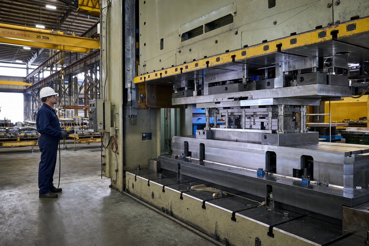
A die that has been sharpened, reassembled, and shimmed is not automatically production-ready. Skipping validation after maintenance is like rebuilding an engine and never starting it before bolting it back into the car. The post-maintenance die tryout validation steps that follow are the final quality gate between the toolroom bench and the production press. They confirm that every component sits where it belongs, engages at the correct depth, and produces parts that meet print.
Step-by-Step Post-Maintenance Validation Sequence
How to verify die after sharpening and reassembly follows a strict sequence. Each step builds on the one before it, and skipping ahead creates blind spots that only reveal themselves as defective parts or damaged tooling once full-speed production begins.
- Visual inspection of all reassembled components. Before the die leaves the bench, verify that every punch is seated fully in its retainer, all fasteners are torqued to specification, springs are installed in the correct pockets without cocking, and no foreign debris remains in the die cavity. Check that all dowel pins are flush and no components protrude beyond their intended surfaces.
- Shut-height verification. Die shut height verification after maintenance confirms the die closes to the correct dimension after sharpening and shimming. Place gauge blocks or a calibrated height gauge across the stop blocks and verify the reading matches the die's documented shut height within 0.001 inch (0.025 mm). Any deviation means shims were miscalculated or a component was not seated properly.
- Safety-strap and fastener check. Confirm all die clamp slots are accessible and undamaged. Verify that safety straps or keeper bolts that prevent the upper die from separating during transport are in place. This protects both the die and the setup technician during press loading.
- Dry-cycle testing without material. Load the die into the press and cycle it slowly, without strip material, through several complete strokes. Watch for interference between punches and strippers, listen for contact where none should exist, and verify that all moving components travel smoothly through their full range. This step catches reassembly errors that visual inspection alone cannot detect.
- Short-run tryout with first-article measurement. Feed material and run 10 to 20 parts at reduced speed. Pull the first complete part and measure all critical dimensions, burr heights, hole locations, and formed features against the part print. Compare these measurements to the last known-good sample from the previous production run. Any deviation beyond tolerance indicates a maintenance or reassembly issue that must be resolved before releasing the die.
- Sign-off and release to production. Once first articles pass inspection, the technician signs off the maintenance record with the validation date, stroke count at release, and a confirmation that all checklist items are complete. This creates accountability and a clear handoff point between the toolroom and the production floor.
For progressive dies, two additional checks are essential. First, verify strip progression by feeding material through all stations and confirming that pilot holes align with pilots at every station without elongation or positional drift. Even 0.005 inch of misalignment at the first pierce station compounds across downstream stations. Second, inspect the last strip produced during tryout for consistent carrier integrity, uniform part separation, and clean scrap shedding at every cutoff point. As die setup experts emphasize, incorrect pilot-release timing after reassembly can cause elongation of pilot holes, bent pilots, and poor part location, problems that only appear once the strip is fully threaded through the tool.
This stamping die production readiness checklist closes the loop on every maintenance cycle. Without it, technicians have no proof the work they performed actually restored the die to a capable state. With it, production inherits a validated tool rather than a hope that things went back together correctly.
Building a Maintenance-Ready Die Program
Validation catches reassembly errors. But the broader question is why some dies require intensive intervention every few weeks while others run reliably for months between services. The answer almost always traces back to how the die was designed and built in the first place.
Die longevity does not start on the maintenance bench. It starts at the engineering stage. Dies built with maintenance accessibility, meaning components that can be removed and measured without full disassembly, reduce the time and skill required for every service event. Durable tool steels selected for the specific material being stamped resist edge wear longer and extend intervals between sharpening. Stable production geometry, features designed to hold tolerance across hundreds of thousands of strokes without drift, keeps parts in spec without constant adjustment.
Consider what makes a die easy to maintain over its full lifecycle:
- Punches retained in quick-change holders rather than press-fit bores allow replacement without pulling the entire upper assembly
- Standardized wear components across multiple dies reduce spare parts complexity and enable cross-die inventory sharing
- Clear station identification markings and reference surfaces give technicians immediate orientation during teardown
- Adequate clearance around springs, pilots, and guide pins so measurements can be taken without removing adjacent components
- Tool steel grades matched to production material hardness, balancing toughness against wear resistance for the specific application
Manufacturers like YICHEN approach custom stamping die manufacturing with this maintainability mindset built in from the start. Their engineering attention pairs durability and stable production performance with practical access for the technicians who will service the die throughout its life. The result is a die program that requires less intensive intervention over the tool's full lifecycle, fewer emergency repairs, more predictable maintenance windows, and longer total service life before major reconditioning becomes necessary.
A well-validated, well-designed die returned to the press after proper maintenance is not just a repaired tool. It is a known quantity: measured, documented, and confirmed ready. That confidence, built on structured procedures rather than assumptions, is exactly what separates shops that control their tooling costs from shops that are controlled by them. Your stamping die maintenance checklist is the document that makes this discipline repeatable, shift after shift, die after die.
Stamping Die Maintenance Checklist FAQs
1. How often should a stamping die be serviced?
Stamping die service frequency depends on stroke count rather than calendar time. A three-tier approach works best: Level 1 operator checks occur every production run, Level 2 technician inspections happen every 10,000 to 50,000 strokes, and Level 3 full teardowns are triggered every 100,000 to 500,000 strokes. Material hardness, die complexity, and production speed all shift these intervals. Harder materials like stainless steel can halve baseline intervals, while simple blanking dies in mild steel may stretch them further. Track actual wear data over several cycles to refine your specific schedule.
2. What causes excessive burrs on stamped parts and how do you fix it?
Excessive burrs on stamped parts are caused primarily by dull cutting edges or punch-to-die clearance that has opened beyond specification. When burr height exceeds 10% of material thickness, sharpening is overdue. The corrective maintenance steps include measuring actual clearance with feeler gauges, sharpening both punch and die section cutting edges on a surface grinder with flood coolant, and replacing worn die buttons if clearance cannot be restored through sharpening alone. Consistent burr monitoring during production runs catches this degradation early before it produces scrap.
3. When should you sharpen a stamping die versus replace the punch?
The sharpen versus replace decision rests on three measurable factors. First, track cumulative material removed from the punch over its lifetime; when total grinding depth approaches the engineering limit documented on the die design, replacement is necessary. Second, check remaining cutting land length, as punches need minimum engagement with strippers and die openings. Third, watch for signs of subsurface thermal damage such as discoloration or repeated chipping after sharpening. If none of these limits are reached, sharpening with light passes of 0.001 to 0.002 inch per downfeed restores the edge effectively.
4. What spare parts should a stamping die shop keep in stock?
Priority spare parts are ranked by wear rate multiplied by supplier lead time. Custom-profile punches top the list because they wear fastest and often require weeks to manufacture. Stock at least one full set per high-volume die. Die buttons, springs, and pilot pins follow closely. Springs should be stocked as complete sets per die with replacement triggered when free length drops 10% from nominal. Pilots worn 0.01 mm undersize need immediate replacement. Guide pin bushings, stripper inserts, and fastener kits round out the inventory. Minimum quantities should cover one full replacement cycle plus a buffer set based on your supplier lead times.
5. How can die design reduce long-term maintenance costs?
Dies engineered with maintainability in mind significantly reduce lifetime maintenance burden. Key design features include quick-change punch holders that allow replacement without full disassembly, standardized wear components that simplify spare parts inventory, clear station identification markings for fast technician orientation, and adequate clearance around springs and pilots for in-place measurement. Manufacturers like YICHEN (https://www.yichen-group.com/stamping-die/) incorporate these principles into custom stamping die manufacturing, pairing durable tool steels matched to production materials with practical access points that make routine service faster and more consistent across technician skill levels.


