


Defining Individual Stamping Die Geometry
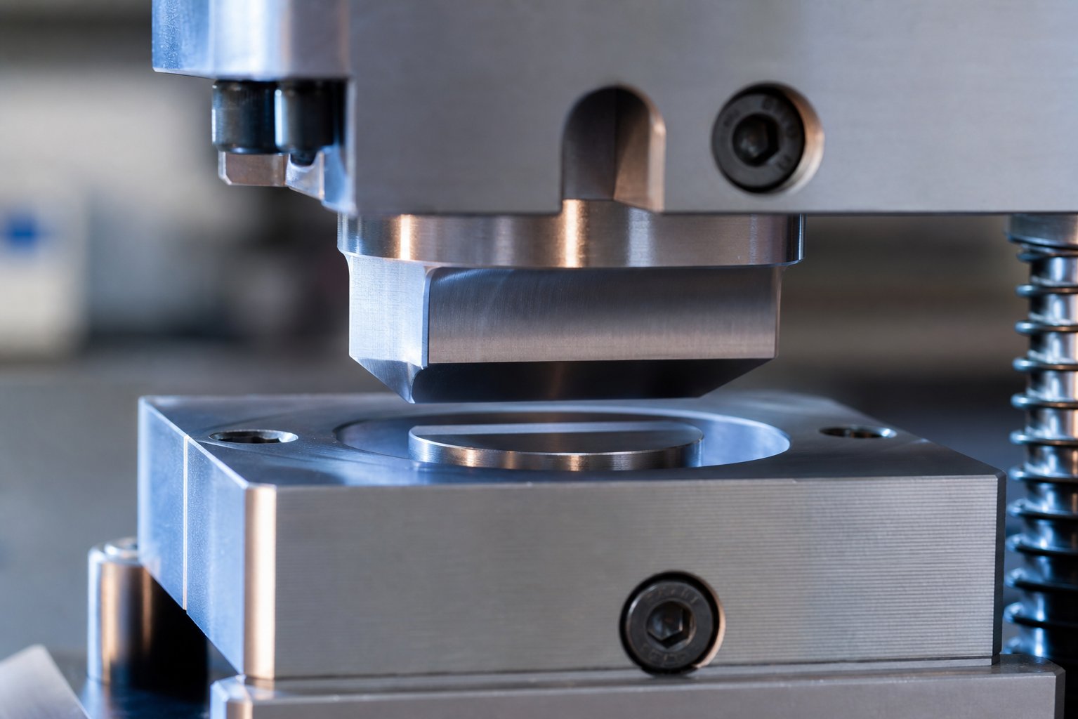
Every stamped part starts as a geometric argument between punch, die button, stripper, and workpiece. The outcome of that argument - whether you get a clean part or a scrap bin full of rejects - depends entirely on the measurable spatial relationships engineered into a single-station die. That collection of dimensional relationships is what we mean by individual stamping die geometry.
Individual stamping die geometry is the complete set of measurable spatial relationships - clearances, radii, angles, and land dimensions - between the punch, die button, stripper, and workpiece within a single-station die optimized to perform one discrete stamping operation.
What Individual Stamping Die Geometry Means in Practice
In practice, this means every geometric feature serves a specific mechanical function. Punch-to-die clearance governs how material fractures. Die land length controls slug behavior. Entry radii dictate material flow. These are not abstract CAD dimensions - they are the physical boundaries that determine whether metal shears cleanly or tears unpredictably. A single-stage die performs one operation per press stroke, and every geometric parameter within it exists to make that single operation repeatable across thousands or millions of cycles.
Why Geometry Matters More Than Die Type Classification
Engineers often classify dies by function - blanking, piercing, bending, drawing. That classification tells you what the die does, not how well it does it. Geometry is the "how well." Two blanking dies with identical layouts but different clearance angles will produce measurably different edge conditions, burr heights, and tool wear rates. Die design decisions at the geometric level are where performance separates from mediocrity.
Individual Dies vs Progressive Die Stations as Geometric Systems
A progressive die design links multiple stations into one strip-fed system - each station handles a different operation, and geometric compromises emerge because stations share a common strip pitch and feed plane. An individual die in manufacturing carries no such constraints. It is a self-contained geometric system where every parameter can be optimized exclusively for its single operation without accommodating adjacent stations. That independence is both its strength and its design responsibility: there is no neighboring station to compensate for a geometric shortfall.
Part quality, die life, press tonnage, strip control - each of these downstream outcomes traces directly back to geometry decisions made at the design stage. The parameters that drive those outcomes deserve more than a passing mention. They deserve a full breakdown.
Core Geometric Parameters Every Die Designer Must Control
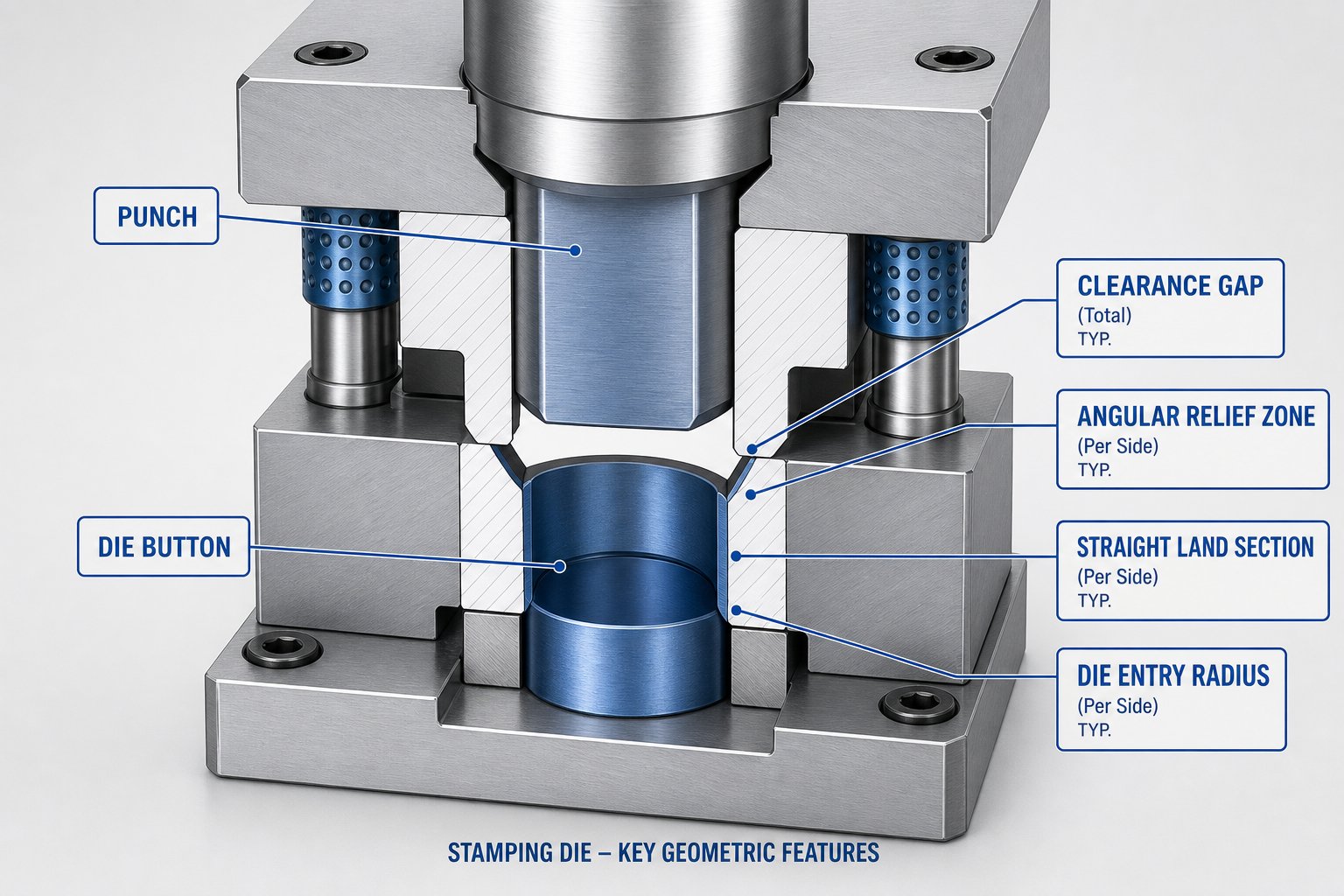
Six measurable parameters define how an individual stamping die behaves under load. Each one has a distinct mechanical role, and each one interacts with the others in ways that can either reinforce performance or quietly undermine it. Treating them as isolated numbers on a drawing is a common mistake - they function as a system. Here is what each parameter actually does and why it matters to your stamping die design.
Punch-to-Die Clearance as a Percentage of Material Thickness
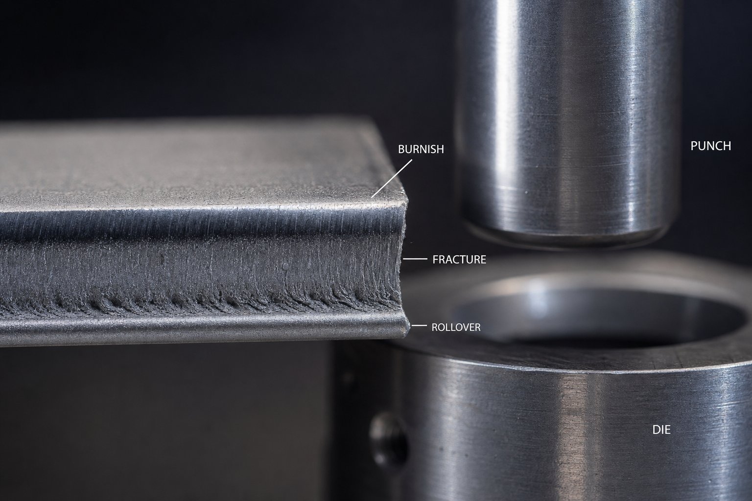
Clearance is the gap between the punch cutting edge and the die button cutting edge, measured per side. You will also hear it called offset or gap - same geometric feature, different measurement conventions. This single value controls how fracture lines propagate through the workpiece. When clearance is correct, the fracture planes initiated at the punch edge and the die edge meet cleanly in the middle of the material thickness, producing a smooth sheared zone with minimal burr.
The standard approach expresses clearance as a percentage of material thickness per side. A general starting point is around 10% per side for mild steel, though modern practice often pushes toward 11-20% to reduce tooling strain and extend operational life. Harder, higher-tensile materials demand increased clearance because they resist plastic deformation before fracture. Softer materials like copper and aluminum work well at tighter percentages. The key point: clearance is not a fixed number - it scales with what you are cutting.
Angular Clearance and Die Land Length Relationships
Angular clearance is the relief angle machined below the die land - the tapered opening that allows slugs or blanks to fall freely after separation. Without it, cut slugs wedge inside the die opening, get dragged back up with the punch on the return stroke, and cause slug pulling. That leads to die damage, part defects, and unplanned downtime.
Die land length is the straight, parallel section at the top of the die opening before the angular relief begins. It serves two purposes: it supports the material during shearing to maintain hole quality, and it provides regrind stock. A longer land improves cut quality but increases the risk of slug retention. A shorter land eases ejection but wears into the relief zone faster, shortening die life between regrinds. These two parameters - land length and relief angle - must be balanced together. You cannot optimize one without considering the other.
Shear Angle Application on Punch and Die Faces
Shear angle is a deliberate slope ground onto the face of the punch or the die block so that cutting does not happen all at once across the full perimeter. Instead, material engages progressively - like scissors versus a guillotine. This reduces peak cutting force significantly, which means lower press tonnage requirements and less shock loading on stamping die components.
The trade-off is lateral thrust. Angled shear creates a side force component that tries to push the punch off-center. It also increases snap-through energy - the sudden release when the punch breaks through - which can cause strip lifting if the stripper system is not designed to handle it. Punch nose radius plays into this as well: the geometry at the punch tip influences how cleanly the punch enters the material and how much strip lifting force develops during retraction. A flat-faced punch grabs the strip more aggressively than one with a slight radius or back-taper.
Die entry radius - the small radius at the top edge of the die opening - controls how material flows into forming cavities and reduces stress concentration at the cutting edge in drawing operations. In cutting dies, a sharp entry edge is essential for clean shear; in forming dies, a generous entry radius prevents material tearing.
| Parameter | Definition | Typical Range | Primary Function |
|---|---|---|---|
| Punch-to-Die Clearance | Gap between punch and die cutting edges, per side | 5-20% of material thickness | Controls fracture plane alignment and edge quality |
| Angular Clearance (Relief) | Taper angle below the die land | 0.5 to 2 degrees per side | Enables slug/blank ejection, prevents slug pulling |
| Die Land Length | Straight parallel section at top of die opening | 2-5 mm depending on application | Supports material during shear, provides regrind allowance |
| Shear Angle | Slope ground on punch or die face | 1-3 degrees or 1x material thickness | Reduces peak cutting force by progressive engagement |
| Punch Nose Radius | Geometry at the punch cutting tip | Sharp to slight radius per application | Influences strip lifting and material entry behavior |
| Die Entry Radius | Radius at upper edge of die opening | Sharp (cutting) to 4-10x thickness (drawing) | Controls material flow and stress concentration |
A quick terminology note: clearance, gap, and offset all describe the same geometric feature. Clearance is the most universal term in stamping die parts documentation, gap appears in shop-floor language, and offset shows up in CAD modeling contexts. They measure the same space - just be consistent within your own documentation.
These six parameters do not operate in isolation. Changing clearance alters the force required to cut, which changes how much benefit you get from shear angle. Adjusting land length shifts the regrind interval, which affects how long your angular clearance remains effective. Every geometric decision ripples through the system. The differences between operation types - blanking versus bending versus drawing - only amplify these interactions.
Operation-Specific Geometry Across Die Types
A clearance value that produces perfect blanked edges will destroy a drawing die. A bend radius optimized for springback compensation has no relevance in a piercing operation. Each operation type carries its own geometric DNA - a distinct set of spatial relationships tuned to a specific deformation mode. When you treat all types of stamping dies as geometric variations of a single template, you set yourself up for failures that no amount of troubleshooting will fix at the press.
Cutting Die Geometry for Blanking and Piercing Operations
Blanking and piercing are both shearing operations, but their geometric priorities differ in one critical way: in blanking, the die opening defines the finished part, so the die is sized to the part dimension and the punch is undersized by the clearance amount. In piercing, the punch defines the hole, so the punch matches the desired dimension and the die opening is oversized by clearance.
Beyond that sizing distinction, both operations demand the same geometric controls - precise punch-to-die clearance, shear angle, angular relief, and die land length. Clearance governs how cleanly fracture planes propagate. Research on advanced high-strength steels shows that clearances ranging from 6% for mild steel up to 16% or higher for ultra-high-strength grades produce optimal edge conditions. Too tight, and you get secondary shear and microcracks. Too loose, and excessive rollover and burrs appear.
Shear angle on the punch face further separates cutting geometry from other operation types. A beveled or rooftop punch profile can reduce peak piercing force by more than 50% while simultaneously improving edge ductility - but that same angled geometry would be meaningless in a bending die. The geometric optimization here is entirely about controlling fracture mechanics and managing snap-through tonnage.
Bending Die Radius Profiles and Springback Compensation
Bending dies abandon the fracture-focused geometry of cutting dies entirely. There is no clearance in the cutting sense - instead, the defining geometric parameter is the punch nose radius and the V-die opening profile. These two features determine the natural internal bend radius of the formed part.
Imagine pressing a punch with a 2 mm tip radius into a 16 mm V-die opening. The sheet does not conform tightly to the punch - it forms a natural parabolic curve governed primarily by the die opening width. For mild steel, the resulting internal radius approximates 16% of the V-opening width. Stiffer materials like stainless steel push that up to 18-20%.
Springback compensation adds another geometric layer entirely absent from cutting dies. When the punch retracts, the bent material partially rebounds due to elastic recovery. Higher-strength materials spring back more aggressively - stainless steel rebounds 2 to 3 degrees, while high-strength steels can spring back 5 to 15 degrees. The stamping design must account for this by overbending, adjusting die angles, or modifying radius profiles so the final part geometry lands within tolerance after elastic recovery.
Drawing Die Entry Geometry and Material Flow Surfaces
Drawing operations introduce geometric concerns that neither cutting nor bending dies share: material flow control across large surface areas. The critical geometry here includes die entry radius, punch nose radius, draw bead profiles, and blank holder surfaces - all working together to manage how sheet metal flows into a cavity without tearing or wrinkling.
Die entry radius is arguably the most sensitive parameter. If it is too small, material cannot flow freely and the cup wall fractures from excessive stretching. If it is too large, material wrinkles after leaving the pinch point between the draw ring and binder. Guidelines for draw-quality steel suggest entry radii scaled to both material thickness and blank diameter, with high-wear tool steel used for these radii due to the constant material sliding contact.
Draw bead geometry - the raised profiles machined into the binder surface - controls flow resistance by forcing material to bend and unbend as it enters the die. Their height, shape, and placement are geometric tools for balancing metal flow between tight corners and straight walls. This type of flow-management geometry simply does not exist in cutting or bending dies.
- Blanking/Piercing: Geometric priorities center on clearance percentage, shear angle, die land length, and angular relief - all optimized for clean fracture propagation, slug ejection, and minimizing cutting force.
- Bending: Geometry revolves around punch radius, V-die opening profile, and overbend compensation - optimized for controlling the natural bend radius and counteracting elastic springback.
- Drawing: Critical geometry includes die entry radius, punch nose radius, draw bead height and profile, and blank holder gap - all optimized for uniform material flow without tearing or wrinkling.
A 10% clearance that gives you a clean blanked edge would be completely irrelevant in a bending context. A generous 8 mm entry radius essential for deep drawing would eliminate the sharp edge required for piercing. This is precisely why individual die geometry must be treated operation by operation - the geometric profile of each operation type reflects fundamentally different material deformation mechanics. And those mechanics shift again when you change the material itself.
Material Properties That Shape Die Geometry Decisions
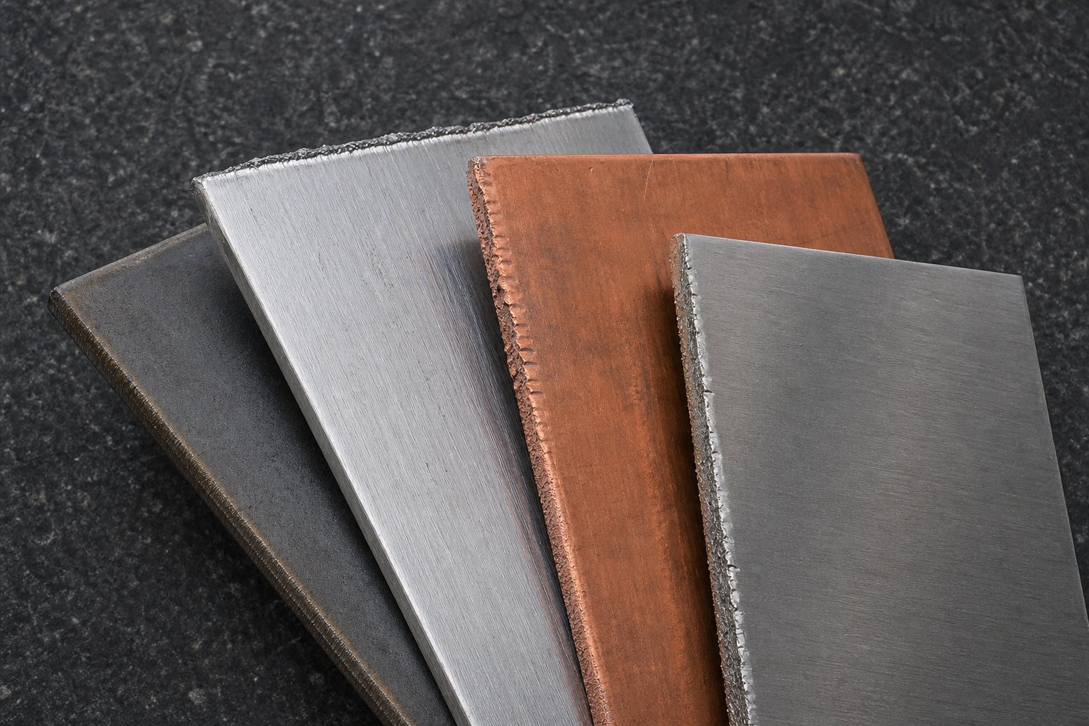
The same die geometry that works flawlessly in mild steel can produce cracked edges in stainless or excessive burrs in aluminum. Material is not a secondary input to metal stamping die design - it is the primary driver that sets every geometric starting point. Ductility, tensile strength, work-hardening rate, and thickness all dictate how aggressively you can shear, how tightly you can bend, and how much clearance you need to achieve clean fracture.
How Material Ductility Drives Clearance Selection
Ductile materials like copper and low-carbon steel allow fracture planes to propagate cleanly at relatively tight clearances. Harder, higher-tensile materials resist that fracture propagation and need more mechanical leverage - a wider gap - to break the slug away without generating excessive burr or edge damage. The general rule: as yield-to-tensile strength ratio decreases, clearance must increase.
Consider the practical spread. Mild steel typically works well at roughly 10% clearance per side. Stainless steel, with its higher work-hardening rate and tensile strength, actually performs poorly at that same 10% - research shows it produces the worst burr height at that value. Moving to 12-15% often yields cleaner edges. Advanced high-strength steels push this further, with studies indicating clearances up to 21% per side for optimal edge-stretching capability. Aluminum, despite being softer, benefits from moderate clearances because its tendency toward galling and adhesive wear changes the failure mode at the shear plane.
The die clearance for different materials is not a matter of preference - it is a matter of fracture mechanics dictated by each alloy's deformation behavior.
Radius Requirements Across Common Stamping Alloys
Bend radius for sheet metal stamping follows the same material-dependent logic. Stiffer, less ductile materials crack at tighter radii because the outer fibers of the bend exceed their elongation limit. A common rule of thumb ties minimum bend radius directly to material thickness multiplied by a factor that reflects the alloy's ductility:
- Mild steel: 0.8 to 1.2 times material thickness for thin gauges, increasing to 1.5-2.5x for thicker stock.
- Stainless steel: 2x thickness minimum for thin gauges, scaling to 3-4x for heavier plate - reflecting its higher springback and lower ductility at the bend apex.
- Aluminum: 1x thickness for light gauges, 2-3x for thicker sections. Punch radii for deep draws should sit at 8 to 10 times material thickness, with die entry radii at 5 to 10 times thickness.
Copper and brass, being highly ductile, allow tighter radii than steel at equivalent thickness - but their formability depends heavily on alloy composition and temper condition.
Thickness-to-Geometry Relationships for Ferrous and Non-Ferrous Metals
Stamping die material selection is only half the equation. Thickness within any given alloy shifts the geometric requirements significantly. Thicker sheets demand larger clearances in absolute terms (though the percentage may hold steady), wider V-die openings for bending, and more generous draw radii. The table below provides a material-to-geometry reference for the most common stamping alloys.
| Material Category | General Clearance Range (per side) | Minimum Bend Radius Principle | Geometric Notes |
|---|---|---|---|
| Mild Steel (low-carbon) | 8-12% of material thickness | 0.8-1.2x thickness (thin gauge) | Baseline reference for most die geometry guidelines |
| Stainless Steel (austenitic) | 12-16% of material thickness | 2-4x thickness depending on gauge | Requires 2-3x press force vs mild steel; draw clearance needs thickness + 35-40% additional |
| Stainless Steel (ferritic) | 10-14% of material thickness | 1.5-2.5x thickness | Less aggressive than austenitic; draw clearance needs thickness + 10-15% additional |
| Aluminum (drawing grades) | 8-12% of material thickness | 1-3x thickness depending on gauge | Punch radius 8-10x T for draws; galling risk requires polished die surfaces |
| Copper and Brass | 6-10% of material thickness | 0.5-1.5x thickness (alloy dependent) | High ductility allows tight radii; formability varies significantly with temper and alloy |
| Advanced High-Strength Steel | 14-21% of material thickness | 2-4x thickness | Low yield-to-tensile ratio demands wider clearance for edge quality |
These values are starting points, not absolutes. Actual production geometry depends on part tolerance requirements, die life targets, surface finish expectations, and the specific alloy grade in question. Engineers should consult material data sheets and validated tooling references for precise project values - a 5000-series aluminum behaves very differently than a 6000-series under the same punch geometry.
What this table makes clear is that no single geometric recipe works across materials. Every clearance percentage, every radius multiplier, every draw geometry assumption shifts the moment you change the alloy on the press. And those shifts do not just affect one outcome - they create trade-offs where optimizing for one result inevitably compromises another.
Geometric Trade-Offs That Define Die Performance
Every geometric decision in an individual die is a negotiation. You cannot maximize edge quality, die life, and force efficiency simultaneously - improving one parameter in isolation always costs you something elsewhere. These trade-offs are not design flaws. They are the physics of stamping, and understanding them is what separates deliberate die clearance optimization from guesswork that creates recurring problems at the press.
The critical question is not "what is the best value" for any single parameter. It is "what am I willing to sacrifice for this specific part, at this volume, to this tolerance?"
Clearance Trade-Offs Between Edge Quality and Die Life
Tighter clearance produces a larger burnish zone and a cleaner sheared edge - that much is well established. But the cost is real. Smaller gaps mean the punch and die cutting edges endure higher contact stresses with every stroke. That accelerated abrasion shortens regrind intervals and increases the risk of chipping, especially in higher-strength materials.
On the other side, wider clearance extends tool life by reducing punch wear - using clearance values of 11-20% can considerably reduce tooling strain during piercing. But you pay for that longevity with increased rollover, a rougher fracture zone, and potentially larger burrs on conventional steels. Research on advanced high-strength steels adds a nuance: AHSS grades tend to maintain constant burr height regardless of tool wear, meaning wider clearances may not carry the same burr penalty seen in mild steel. Context matters.
Radius Geometry Balancing Formability Against Dimensional Control
In bending and drawing operations, larger radii reduce stress concentration at the bend apex or draw entry. That means less cracking risk, lower forming force, and gentler tool wear. Sounds like an easy win - until you consider what happens downstream.
A generous bend radius allows more elastic springback, making final angle control harder to predict and compensate. In drawing, an oversized entry radius lets material flow too freely, inviting wrinkles in unsupported regions. You end up trading reliable formability for dimensional instability that shows up as part-to-part variation in production.
Shear Angle Benefits vs Lateral Force Penalties
Shear angle is one of the most effective stamping design tips for reducing peak tonnage. A beveled punch engaging material progressively rather than all at once can cut peak piercing force by more than 50%, with studies on DP steels confirming reductions exceeding 50% with bevel angles between 3 and 6 degrees. That is a meaningful reduction in press stress and snap-through shock.
The penalty: shear angle introduces a lateral force vector that tries to deflect the punch sideways. Greater angles generate greater lateral thrust, demanding stiffer guide systems and tighter punch-to-stripper fits. Snap-through energy - the sudden force reversal when the punch breaks through - also increases, which can cause strip lifting and fatigue damage to press components over millions of cycles.
- Tighter clearance: Gain cleaner sheared edges and larger burnish zones. Sacrifice accelerated punch and die wear, higher cutting forces, and increased alignment sensitivity.
- Wider clearance: Gain extended die life and lower punching force. Sacrifice increased rollover, rougher fracture zones, and potential burr growth in ductile materials.
- Larger bend/draw radius: Gain reduced cracking risk and lower forming stress. Sacrifice dimensional control due to increased springback and wrinkling potential.
- Greater shear angle: Gain reduced peak cutting force and lower press tonnage demand. Sacrifice increased lateral thrust on the punch, higher snap-through energy, and greater strip lifting risk.
- Longer die land: Gain better hole quality and more regrind stock. Sacrifice increased slug retention risk and higher frictional drag on cut material.
How you resolve these trade-offs depends on the tolerance tier of the stamped part. Tight-tolerance work - medical components, electrical connectors, precision brackets - demands geometry that favors part quality even at the cost of shorter die life and more frequent maintenance. The stamping die performance factors that matter here are edge condition, dimensional repeatability, and surface finish.
High-volume commercial work flips the priority. When you are running millions of simple brackets or commodity clips, die longevity and uptime dominate. Wider clearances, more generous radii, and moderate shear angles keep the press running longer between service intervals - and the relaxed tolerances can absorb the geometric compromises without rejecting parts.
This tolerance-tier lens gives you a decision framework rather than a single "correct" value for any parameter. The geometry itself does not change - only the priority you assign to each outcome changes based on what the part demands. And within each of those geometric decisions, secondary features like relief angles and bypass notch profiles add another layer of design control that extends die performance across its full service life.
Relief Geometry and Bypass Notch Design Principles
Relief angles and bypass notches rarely get the design attention of clearance or shear geometry - yet they are the features that keep slugs falling, strips feeding, and dies running between regrinds. Get the die relief angle geometry wrong, and you will spend more time clearing jammed slugs than producing parts.
Angular Relief and Straight Land Geometry for Slug Ejection
Picture what happens at the bottom of a cutting stroke. The punch shears through the material, and a slug sits inside the die opening. On the return stroke, that slug needs to drop clear - not ride back up with the punch into the strip. This is where angular relief earns its keep.
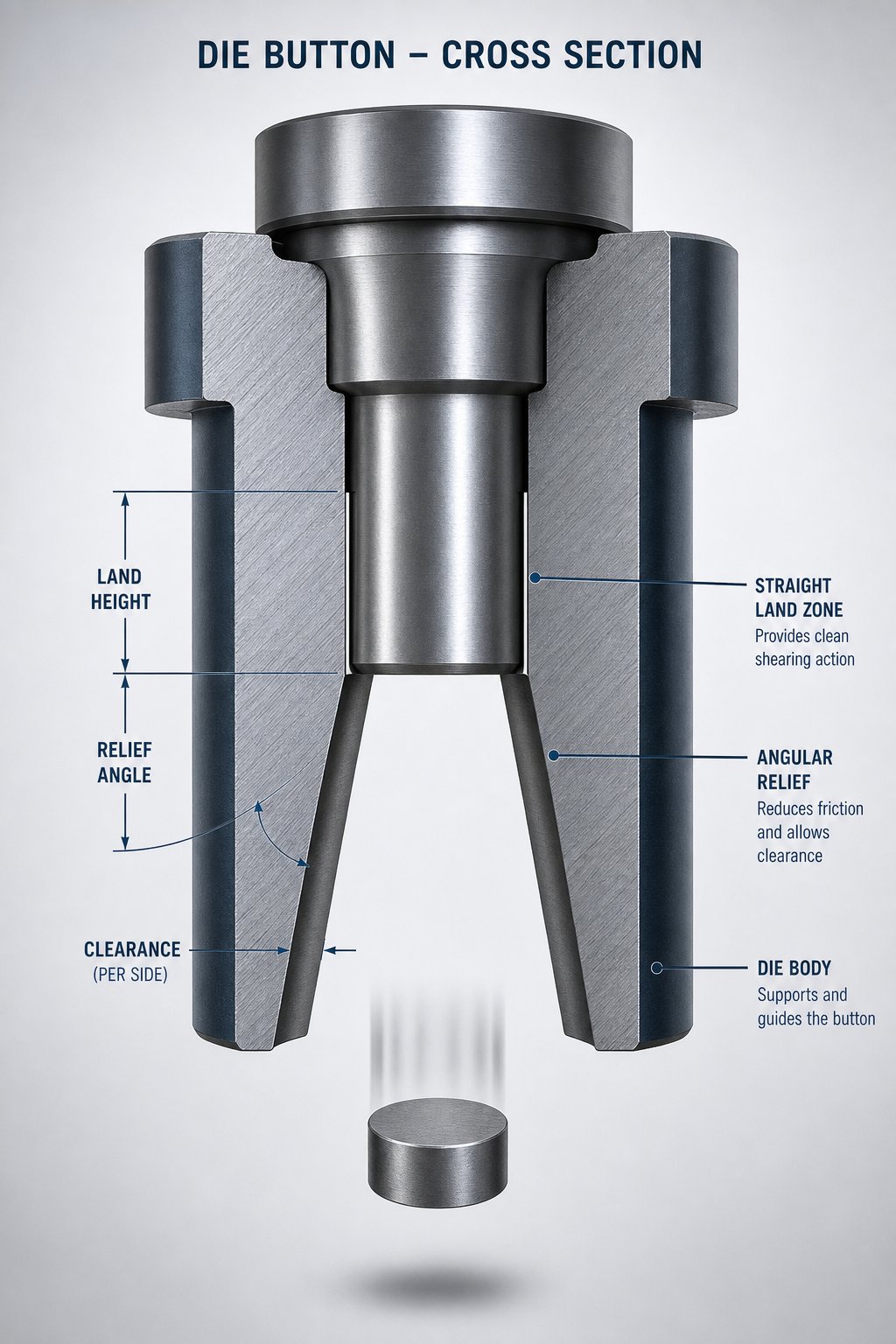
Angular relief is the taper machined below the die land that creates an expanding clearance path for the slug. Once the slug clears the straight land zone, it enters a widening cavity with zero resistance, falling freely through the die shoe. Without this relief, slugs wedge against the die walls, stack up, and eventually get dragged back through the strip - the classic slug pulling failure that stops production cold.
The straight land itself - that parallel section at the very top of the die opening - serves as the precision zone. It supports the material during shear and maintains hole quality by keeping the cutting geometry consistent. Common land lengths range from 0.060 to 0.125 inches for standard applications, with the relief taper below typically set at 0.15 to 0.5 degrees per side. Thinner materials and smaller hole diameters lean toward the shorter land lengths; heavier gauges and larger openings tolerate longer lands.
The combination matters more than either value alone. A short land paired with aggressive relief eases ejection but sacrifices regrind life. A long land with shallow relief maximizes sharpening cycles but increases slug retention risk - especially at high stroke rates where vacuum and oil viscosity work against gravity. For slug pulling prevention in stamping dies, the goal is to retain the slug just long enough for the punch to retract, then release it with zero resistance into the relief zone.
Positive and Negative Bypass Notch Profiles Explained
Bypass notches serve an entirely different geometric function. While relief geometry manages what happens after the cut, bypass notches manage what happens before it - specifically, how the strip positions itself relative to the die stations.
A positive bypass notch is a raised feature on the die surface that deflects or lifts the strip as it feeds forward, preventing the strip from catching on die edges or previously formed features. A negative bypass notch is a recessed channel that allows formed features to pass through without interference. Both negative and positive bypass notches in sheet metal stamping dies solve the same fundamental problem: maintaining consistent strip travel so that the material registers accurately at the cutting or forming station.
The purpose of bypass notches in stamping dies extends beyond simple interference clearance. They control strip deflection, prevent material buckling between stations, and ensure pilots can engage their holes without fighting a misaligned strip. In individual dies used with hand-fed or short-feed applications, bypass notches are less common - but when multiple features exist on a single die face or when strip lifters interact with formed geometry, they become essential positioning tools.
Regrind Allowance Built Into Initial Die Geometry
Every sharpening cycle removes material from the die face, and that removal directly shortens the straight land. After enough regrinds, the land disappears entirely into the relief zone - and your precision cutting geometry becomes a tapered funnel that produces oversized holes and excessive burrs.
Experienced die designers build regrind allowance into the initial geometry by specifying a land length long enough to survive a planned number of sharpening cycles. If each regrind removes 0.003 to 0.005 inches and you want 20 regrind cycles before the die section needs replacement, your initial land must account for that cumulative stock removal while still maintaining minimum functional land length throughout the die's service life.
This is why initial geometry is never just about first-article performance. It is about performance across the entire lifecycle of the tool.
- Size the straight land for lifecycle, not just first-run quality. Account for cumulative regrind stock removal when specifying initial land length.
- Match relief angle to slug ejection requirements. Higher stroke speeds and thinner materials demand more aggressive relief to counteract vacuum and oil adhesion effects.
- Never let land length reach zero. Establish a minimum functional land threshold and schedule die section replacement before regrinding crosses that limit.
- Use positive bypass notches to lift strips over obstructions and negative notches to recess clearance for formed features passing through the die.
- Verify relief geometry after every regrind. A fresh edge with altered land-to-relief proportions behaves differently than the original geometry - validate slug behavior before returning the die to production.
- Consider bell-mouthing for chronic slug pullers. A slight negative draft at the very top of the die opening can trap slugs below the strip plane without affecting hole quality.
Relief and bypass geometry are maintenance-facing features as much as they are performance features. They determine not just how the die runs today, but how many production cycles it delivers before geometry degrades beyond correction. That lifecycle perspective connects directly to how engineers validate geometric decisions before committing them to hardened tool steel - a process where simulation now plays a defining role.
Validating Die Geometry Through Simulation and Analysis
Geometric decisions on paper are hypotheses. They remain unproven until metal deforms under load - and historically, that proof came from expensive physical tryouts, iterative die rework, and a lot of scrapped material. Stamping die simulation analysis has fundamentally changed that sequence. Finite element analysis (FEA) lets engineers test geometric variations digitally, converging on validated geometry before any tool steel gets machined.
Finite Element Analysis for Geometry Validation
FEA models the entire forming process as a controlled numerical experiment. You feed it your geometric inputs - clearance values, die radii, punch profiles, draw depth, blank holder gaps - along with material properties and friction conditions. The solver then predicts exactly how the sheet will behave: where it thins, where it wrinkles, where it cracks, and how much it springs back after tool removal.
Research on automotive panel stamping demonstrates this directly. Using orthogonal experiment design combined with FEA software, engineers evaluated the impact of blank holder force, die corner radius, die clearance, and friction coefficient on forming outcomes - identifying that die corner radius was the strongest factor influencing maximum thinning rate, while blank holder force most affected wrinkling. That level of parameter sensitivity would take dozens of physical tryouts to isolate. Simulation delivered it in hours.
For finite element analysis die design workflows, the key outputs include forming limit diagrams that map strain states against material failure boundaries, thickness distribution maps showing thinning risk zones, and springback magnitude predictions that inform compensation geometry. Each output traces directly back to the geometric inputs you control.
Simulating Clearance and Radius Variations Digitally
The real power of simulation in tool and die stamping is iteration speed. Imagine you need to evaluate how three different die entry radii interact with two blank holder force levels across two clearance settings. That is twelve geometric configurations. Physically building and testing twelve die variations would be prohibitively expensive. Digitally, you run those twelve cases in parallel and compare results within a single design cycle.
A study on simultaneous blank and tool geometry optimization showed that iterative FEM simulation converged on optimal tool geometry within seven iterations - reducing surface deviations from 3 mm down to under 0.5 mm without unstable oscillations. The process compensated for springback, thinning, and edge geometry simultaneously, something no physical tryout sequence could accomplish that efficiently with advanced high-strength steel prone to significant elastic recovery.
This iterative approach works across all operation types. For cutting dies, simulation predicts stress concentration at shear edges and validates clearance selections against fracture propagation behavior. For drawing dies, it maps material flow paths, identifies wrinkling zones under compressive stress, and optimizes draw bead geometry to balance metal flow. For bending dies, springback prediction algorithms calculate the exact overbend compensation needed for each material and radius combination.
From Simulation Results to Production-Ready Die Geometry
Simulation does not replace tooling expertise - it accelerates the path from concept geometry to proven geometry. The software tells you where the material will fail. It does not tell you why your die shop cannot hold a 0.003 mm tolerance on a complex 3D surface, or how thermal expansion during a production run will shift your validated clearances. Those realities require hands-on die-building knowledge that no solver captures.
CAE-driven die development typically reduces tryout iterations by 30-50% and cuts tool modification costs substantially. The traditional sequence of Design, Manufacture, Tryout, Fix, Repeat transforms into Design, Simulate, Optimize, Manufacture, Minimal Tryout. That compressed cycle is where simulation delivers its clearest ROI - fewer weld-and-regrind loops, less material waste, and faster time to production-ready tooling.
The strongest die geometry outcomes emerge when digital validation and physical die-building expertise work as a closed loop - simulation identifies the optimal geometric window, and experienced toolmakers translate that window into manufacturable, maintainable tooling.
For engineers working on complex individual die geometry challenges - deep draws with tight radii, multi-feature cutting dies, or high-strength materials with narrow forming windows - collaborating with experienced die solution providers bridges the gap between simulation outputs and production reality. YICHEN's stamping die services offer custom die design support covering structure, components, clearance optimization, and material flow control, connecting simulation-validated geometry to tooling that performs on the press floor.
Simulation gives you confidence in your geometric decisions. But those decisions still produce measurable consequences in production - burr height, springback magnitude, thinning distribution, and die wear rates that either confirm or contradict your analysis. Connecting geometry directly to those quality outcomes is where engineering knowledge becomes process control.
How Die Geometry Drives Part Quality and Tool Longevity
Every quality defect a stamping engineer troubleshoots - burrs, springback, thinning, edge cracking - traces back to a geometric root cause. Not a material batch issue. Not a press malfunction. Geometry. The spatial relationships built into the die at design stage predetermine what the stamped part will look like thousands of strokes later. Understanding die geometry and part quality as a cause-and-effect system is what converts reactive problem-solving into proactive process control.
How Clearance Geometry Controls Burr Formation
Burr height is the single most common quality complaint in cutting operations, and it is governed almost entirely by punch-to-die clearance. When clearance is too tight, the punch grinds against the die wall on every stroke, creating abrasive wear that progressively increases burr height as the edge deteriorates. Research on MART1400 steel demonstrates that increasing clearance from 6% to 14% per side actually reduces burr height - contradicting the old assumption that wider gaps always mean bigger burrs.
The mechanism is straightforward. Proper clearance allows fracture planes to propagate cleanly from the punch edge and die edge, meeting in the middle of the sheet thickness. When those planes align, the slug separates with minimal material dragging at the exit surface - and dragging is what creates burr. Too-tight clearance forces secondary shear, which tears material rather than fracturing it cleanly. Burr control in stamping dies starts with selecting clearance that matches both the material's tensile strength and its thickness, not a single rule-of-thumb percentage applied across everything on the press.
There is also a wear feedback loop. If the pierced hole begins shrinking relative to the punch diameter, abrasive wear is eroding the punch surface. If the hole begins growing, adhesive wear is seizing material onto the punch. Both failure modes trace back to initial clearance geometry and how it distributes stress across the cutting edges over time.
Radius Geometry and Its Effect on Springback and Thinning
Springback is an elastic recovery problem, and its magnitude is a direct function of the bend radius geometry built into the die. Studies on AHSS grades confirm a nearly linear relationship between tensile strength and angular springback - meaning higher-strength materials demand more aggressive geometric compensation. The die radius sets the strain level at the bend apex, and that strain level determines how much elastic energy remains in the part after forming.
Sidewall curl adds another dimension. When sheet metal bends over a die radius and then unbends entering the sidewall, each surface of the sheet experiences different strain histories - tension on one side, compression on the other. That stress gradient through the thickness causes the wall to curl after unloading. Tighter die radii and higher sidewall tension reduce the curl by minimizing the stress differential, but at the cost of increased forming force and greater thinning risk.
In drawing operations, entry radius geometry directly governs material thinning. A radius that is too small restricts flow, forcing the cup wall to stretch beyond safe limits. The resulting thinning concentrates at the punch nose radius - the geometric feature with the sharpest curvature transition. Balancing these radii is a stamping die quality control challenge that determines whether your drawn parts thin uniformly or fail catastrophically at stress concentration points.
Linking Die Life to Initial Geometric Decisions
Die life is not random. It is a predictable function of the stress state imposed on tool steel surfaces by the geometry you designed. Clearance sets the magnitude of shearing stress on cutting edges. Shear angle distributes that stress over time rather than delivering it as a single impact. Land length determines how much material contacts the die wall during every stroke - more contact means more friction, more heat, and faster wear.
The relationship works in both directions. Studies on clearance and vibration reveal that larger clearances introduce measurable vibration during piercing, particularly in higher-strength steels. That vibration promotes chipping over gradual wear - a catastrophic failure mode that ends a die run abruptly rather than degrading quality gradually. Engineers using headed punch retention systems rather than ball-lock systems can mitigate this, but the root cause remains geometric: the clearance value selected at design stage predetermined the vibration profile the tool assembly would experience in production.
| Geometric Parameter | Part Quality Outcome Controlled | Die Life Factor Influenced |
|---|---|---|
| Punch-to-Die Clearance | Burr height, edge condition, hole size accuracy | Punch abrasion rate, chipping risk, vibration magnitude |
| Bend Radius (punch nose) | Springback angle, angular accuracy, sidewall curl | Punch tip wear, forming force on tool surfaces |
| Die Entry Radius (draw) | Material thinning distribution, wrinkling, surface quality | Radius wear from sliding contact, galling onset |
| Shear Angle | Edge ductility, cut edge straightness, snap-through marks | Lateral thrust on guides, cumulative fatigue on punch body |
| Die Land Length | Hole cylindricity, slug mark presence, shear zone quality | Regrind intervals, slug retention frequency |
| Angular Relief | Slug pull marks on part surface, secondary burr from re-entry | Die section replacement frequency, ejection reliability |
This table is not academic - it is a diagnostic map. When a quality issue appears on the press, the first question should always be: which geometric parameter controls this outcome? Burr growing? Check clearance and land condition. Springback drifting? Examine punch radius wear. Thinning in draws? Measure your entry radius against its original specification. Every symptom has a geometric origin.
Mastering individual stamping die geometry is what separates engineers who react to defects from those who prevent them. Proactive stamping die quality control means designing geometry that accounts for wear progression, maintains critical dimensions across regrind cycles, and delivers predictable part quality throughout the die's full service life - not just at first article.
For tooling engineers seeking custom die solutions that address design-heavy geometry challenges - from punch profiles and lifter geometry to burr control and clearance optimization - YICHEN's stamping die services provide engineering collaboration from concept through production, connecting geometric intent to tooling that holds tolerance on the press floor.
- Clearance controls edge quality: Burr height, rollover depth, and fracture zone cleanliness are all direct outputs of the clearance percentage selected for the material and thickness.
- Radius controls dimensional accuracy: Springback magnitude, sidewall curl, and thinning distribution are set by the bend and draw radii built into the die.
- Shear geometry controls force profile: Peak tonnage, snap-through energy, and lateral thrust all respond to shear angle decisions made at design stage.
- Land and relief control die longevity: Regrind life, slug ejection reliability, and cutting consistency over millions of strokes depend on initial land length and relief angle sizing.
- Every quality symptom has a geometric cause: Troubleshooting starts with identifying which parameter drifted from its design intent - then correcting the geometry, not chasing secondary symptoms.
Frequently Asked Questions About Individual Stamping Die Geometry
1. What is the correct punch-to-die clearance for stamping operations?
Correct clearance depends on material type and thickness. Mild steel typically uses 8-12% of material thickness per side, stainless steel requires 12-16%, aluminum works at 8-12%, and advanced high-strength steels need 14-21%. These values ensure fracture planes from the punch and die edges meet cleanly in the middle of the sheet, producing minimal burr. Tighter clearance improves edge quality but accelerates tool wear, while wider clearance extends die life at the cost of rougher fracture zones. For complex clearance optimization challenges, providers like YICHEN (https://www.yichen-group.com/stamping-die/) offer custom die design support that balances edge quality against tooling longevity for specific production requirements.
2. How does die geometry differ between blanking, bending, and drawing operations?
Each operation type has a fundamentally different geometric profile. Blanking and piercing dies prioritize clearance percentage, shear angle, die land length, and angular relief to control fracture propagation and slug ejection. Bending dies focus on punch nose radius, V-die opening width, and overbend compensation geometry to manage springback. Drawing dies require optimized entry radii, punch nose radii, draw bead profiles, and blank holder gaps to control material flow without tearing or wrinkling. A geometric value optimized for one operation would cause failure in another because each reflects different material deformation mechanics.
3. What causes burr formation in stamping and how does geometry prevent it?
Burr forms when material drags at the exit surface during shearing rather than fracturing cleanly. The primary geometric cause is incorrect punch-to-die clearance. Too-tight clearance forces secondary shear that tears material, while excessively loose clearance allows rollover and rough fracture zones. Research on high-strength steels shows that increasing clearance from 6% to 14% per side can actually reduce burr height. Proper clearance allows fracture planes from the punch edge and die edge to align and meet in the sheet's mid-thickness, separating the slug with minimal material dragging. Die land condition and angular relief also influence burr by affecting how cleanly slugs eject without re-contacting the part surface.
4. What is the purpose of die relief angle and land length in stamping dies?
Die land length is the straight parallel section at the top of the die opening that supports material during shearing and maintains hole quality. Angular relief is the taper machined below the land that creates an expanding clearance path for slugs to fall freely after separation. Together, they prevent slug pulling, where cut slugs ride back up with the punch and damage the strip. Typical land lengths range from 0.060 to 0.125 inches, with relief angles of 0.15 to 0.5 degrees per side. Initial land length must also account for regrind allowance, since each sharpening cycle removes material and progressively shortens the functional land.
5. How does simulation improve stamping die geometry design?
Finite element analysis lets engineers test geometric variations digitally before machining tool steel. Simulation predicts material thinning, springback magnitude, wrinkling risk, and forming force requirements based on clearance, radii, draw depth, and blank holder geometry inputs. Studies show CAE-driven die development reduces physical tryout iterations by 30-50% and cuts tool modification costs substantially. Engineers can evaluate dozens of geometric configurations in parallel, converging on optimized parameters within a single design cycle. However, simulation accelerates rather than replaces tooling expertise. Translating validated digital geometry into manufacturable tooling still requires hands-on die-building knowledge, which is where collaboration with experienced providers like YICHEN (https://www.yichen-group.com/stamping-die/) connects simulation outputs to production-ready tooling.


