


What Custom Die Stamping Actually Means
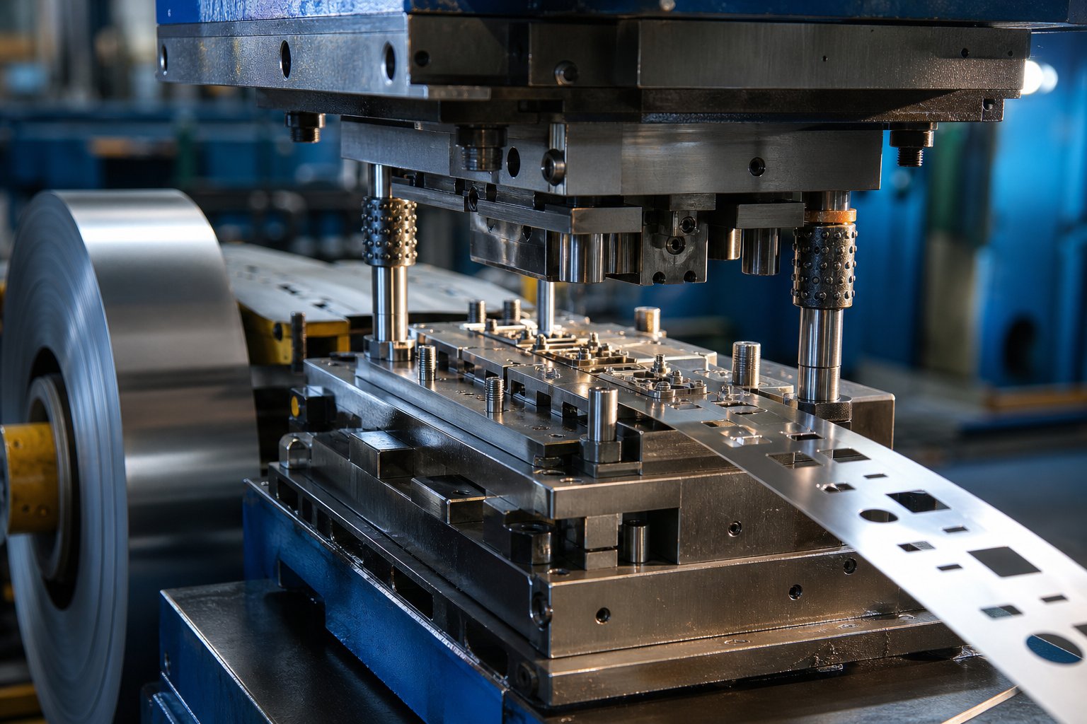
When you hear "metal stamping," you might picture a press punching generic shapes from sheet metal. Custom die stamping is something different. It starts with tooling engineered from scratch for a specific part, its material, and its production demands rather than relying on off-the-shelf dies that approximate the geometry you need.
Custom die stamping is a metal forming process that uses purpose-built tooling, designed for a specific part geometry, material, and production requirement, to produce precision components at scale with repeatable accuracy.
That distinction matters more than it might seem at first glance. A standard die can stamp a washer or a simple bracket. But the moment your part has proprietary dimensions, tight tolerances, or features that interact with other components in an assembly, you need custom metal stamping dies built around your design rather than a design bent to fit existing tooling.
What Makes a Die Custom
A die becomes "custom" when its geometry, station layout, and material specifications are developed exclusively for one part. Imagine the difference between buying a suit off the rack versus having one tailored to your measurements. Off-the-rack works for simple needs. Custom stamping dies are tailored: every punch profile, every clearance, every forming station is calculated for the specific material thickness, ductility, and dimensional targets your part requires.
This upfront engineering includes selecting tool steel grades, designing strip layouts for progressive operations, and compensating for material behaviors like springback. The result is a die stamp that produces virtually identical parts stroke after stroke, whether you are running ten thousand or ten million pieces.
Who Benefits from Custom Die Stamping
Engineers and procurement teams invest in custom tooling for a few core reasons:
- Tighter tolerances - custom dies are engineered to hold your specific dimensional requirements, not just "close enough."
- Unique geometries - proprietary part features, multi-bend profiles, and complex cutouts that no catalog die can produce.
- Higher throughput at scale - a die stamps optimized for your part runs faster with less scrap than adapted tooling.
- Repeatable quality - every part from the die is virtually identical, critical when components must interchange in assemblies.
Industries from automotive to electronics to aerospace rely on a custom die stamp approach whenever part performance, safety, or precision cannot be left to the limitations of generic tooling. If you designed the part yourself, chances are high that you need custom tooling to produce it.
How This Process Fits the Broader Metal Forming Landscape
Custom die stamping sits within a family of metal forming methods that includes CNC machining, laser cutting, casting, and hydroforming. What separates stamping dies from these alternatives is the economics of repetition. A custom die carries a significant upfront investment, but once built, it produces parts at a fraction of the per-unit cost of machining or cutting. That cost advantage compounds with volume, making it the dominant choice for medium-to-high production runs across nearly every manufacturing sector.
This article is built as a decision-making resource. Whether you are an engineer evaluating feasibility or a sourcing professional comparing fabrication methods, the sections ahead cover process types, forming operations, industry requirements, tolerances, cost drivers, and supplier selection, everything buyers wish they had understood before their first custom tooling project.
The first decision most teams face is straightforward: does my project actually need custom tooling, or can standard dies handle the job?
Custom vs Standard Die Stamping and When to Choose Each
A standard die exists on a shelf, ready to stamp common shapes: flat washers, simple brackets, basic clips. It costs little or nothing upfront because the tooling already exists. A custom metal stamping die, on the other hand, is engineered from scratch for your specific part. The choice between these two paths shapes your project economics, design freedom, and long-term production costs in ways that are not always obvious at first glance.
When Standard Dies Fall Short
Standard dies work when your part matches a geometry someone has already built tooling for. Think generic fastener holes, rectangular cutouts, or catalog-spec brackets. The moment your design introduces proprietary dimensions, multi-feature interactions, or material-specific forming challenges, a standard die becomes a constraint rather than a shortcut.
Here is what typically forces the shift to custom tooling:
- Your part has unique dimensional requirements or proprietary features that no existing die can produce.
- Tight tolerances demand tooling engineered specifically for your allowable variation, not a general-purpose approximation.
- Material behavior, such as springback in high-strength steel or galling in aluminum, requires die clearances and compensations tailored to that alloy.
- Multi-operation parts need blanking, piercing, and forming performed in a controlled sequence within one die stamping cycle.
When you force a part into existing tooling, you are designing backward. The tooling dictates what you can make, and your engineers end up compromising geometry, relaxing tolerances, or splitting operations across multiple setups. That flexibility loss often costs more in the long run than the custom stamping die would have upfront.
Design Freedom with Custom Tooling
With a custom metal die stamp approach, the relationship flips. Your part design drives the tooling, not the reverse. The die designer builds every station, every clearance, and every forming profile around your CAD geometry and material spec. You get exactly the part you need without compromises forced by what happens to exist on a shelf.
This matters most for components that must mate precisely in assemblies, meet strict performance criteria, or carry proprietary features that differentiate your product. A custom stamping die also allows optimization of strip layout and forming sequence, which reduces scrap and increases press speed, benefits you will never unlock with adapted standard tooling.
The Break-Even Question Between Standard and Custom
The most persistent misconception about custom tooling is that it is always expensive. In reality, the upfront investment amortizes across every part the die produces. According to real-world project data from Jennison Corporation, a $12,000 custom die producing 20,000 parts adds only $0.60 per piece in tooling cost, while the same design machined without tooling might run $3.50 or more per part.
The break-even math is straightforward: divide the die cost by the per-part savings versus your alternative process. Above that volume threshold, every additional part is dramatically cheaper. Below it, standard approaches or CNC machining may cost less overall.
| Dimension | Standard Die | Custom Die |
|---|---|---|
| Design flexibility | Limited to existing geometries | Engineered to your exact part spec |
| Upfront cost | Low or zero | $8,000 - $50,000+ depending on complexity |
| Per-unit cost at volume | Higher (constrained process) | Significantly lower at scale |
| Geometric complexity | Simple shapes only | Multi-feature, tight-tolerance parts |
| Lead time | Immediate (tooling exists) | 8 - 14 weeks for design and build |
| Ownership | Vendor retains tooling | Buyer typically owns the die |
The real question is not whether you can afford custom tooling. It is whether your total lifetime volume, across all reorders over the next three to five years, crosses that break-even line. If it does, the die becomes an asset that keeps producing value long after it has paid for itself. If it does not, standard or alternative processes remain the smarter investment.
Volume economics, however, are only part of the equation. The type of die you choose, whether progressive, transfer, compound, or fourslide, determines how efficiently that volume runs and what part geometries become possible.
Types of Custom Die Stamping Processes Explained
Choosing the right die type is not a minor detail. It determines your production speed, achievable part complexity, scrap rate, and per-unit economics. Four main types of stamping dies dominate custom work, and each serves a distinct niche. Understanding where they excel and where they fall short helps you avoid expensive mismatches between your part requirements and your tooling investment.
Progressive Dies for High-Volume Complex Parts
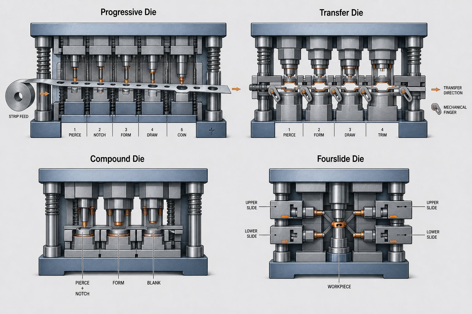
Progressive dies are the workhorse of high-volume metal stamping dies. A coil of sheet metal feeds continuously through a series of stations inside a single die set, with each station performing a specific operation: punching a hole, notching an edge, forming a bend. The strip carries the part from station to station until the final operation separates the finished piece.
Imagine an assembly line compressed into a single tool. That is essentially what progressive dies and stamping achieve. Because the material never leaves the die until the part is complete, cycle times are extremely fast, often producing hundreds of parts per minute. This makes progressive tooling ideal for small-to-medium-sized components like electrical connectors, brackets, lead frames, and shielding cans.
The tradeoff? Progressive dies require higher upfront tooling investment and produce some inherent scrap from the carrier strip. They also work best for parts that remain relatively flat or have shallow forms. Deep-drawn geometries or very large parts push beyond what a progressive strip can handle.
Transfer Dies for Large and Deep-Drawn Components
When parts are too large, too deep, or too complex to stay attached to a strip, transfer dies take over. In this process, the blank is separated from the raw material early and then mechanically transferred between stations by fingers or shuttle systems. Each station performs a forming step, such as deep drawing, flanging, or trimming, on the discrete blank.
Transfer dies are common in automotive body panels, structural components, and appliance housings where part dimensions exceed what progressive strip feeding allows. They handle deeper draws and more aggressive forming sequences because the blank moves freely between stations without the geometric constraints of remaining attached to a carrier strip. The tooling cost sits in the medium-to-high range, and production speeds are slower than progressive dies, but the geometric capability is substantially greater.
Compound and Fourslide Dies for Specialized Geometries
Compound dies take a different approach entirely. Instead of sequencing operations across multiple stations, they perform several cutting operations simultaneously in a single press stroke. A compound die might blank the outer profile and pierce internal holes at the same time, producing flat sheet metal stamping dies parts like washers, gaskets, and electrical laminations with exceptional precision and flatness. They reduce production time by 25-30% compared to sequential operations, though they are generally limited to parts without forming or bending requirements.
Fourslide dies, sometimes called multi-slide dies, use horizontally mounted slides arranged around a central forming area rather than relying solely on vertical press force. These metal press dies move from multiple directions, making them capable of producing complex bends exceeding 90 degrees, tight clips, and intricate wire forms that conventional vertical presses cannot achieve. According to production data from Keats Manufacturing, fourslide machines produce up to 375 parts per minute while generating 31% less scrap than progressive stamping because they eliminate the need for pilot holes and carrier strips.
Fourslide tooling works best for small, thin parts with complex multi-directional bends, such as clips, clamps, connectors, and spring contacts. The limitation is size: larger or thicker materials typically require conventional metal press dies in progressive or transfer configurations.
Selecting among these types of stamping dies comes down to a handful of measurable criteria. Ask yourself these questions in order:
- What is your annual production volume? High volumes favor progressive dies. Low-to-medium volumes may justify transfer or compound approaches.
- What are the part dimensions and depth? Large or deep-drawn parts require transfer dies. Small, flat parts suit compound dies. Small parts with complex bends point to fourslide.
- How complex is the geometry? Multi-directional bends and tight radii favor fourslide. Multi-feature flat parts with cutting and piercing fit compound dies. Parts needing sequential forming and cutting across many features align with progressive tooling.
- What material and thickness are you stamping? Thin, flexible materials work across all types. Thicker or harder materials may rule out fourslide and favor progressive or transfer configurations with higher press tonnage.
- What tolerance and flatness requirements apply? Compound dies deliver superior flatness on cut parts. Transfer dies provide tighter dimensional control on deep-drawn geometries.
| Die Type | Volume Range | Part Size Limits | Complexity Capability | Typical Lead Time |
|---|---|---|---|---|
| Progressive | High (100K - millions) | Small to medium | Multi-feature sequential operations; limited draw depth | 10 - 16 weeks |
| Transfer | Medium to high (50K+) | Medium to large | Deep draws, complex 3D forms, large geometries | 12 - 20 weeks |
| Compound | Medium to high (50K+) | Small to medium (typically under 150 mm) | Simultaneous cut operations; flat parts only | 6 - 10 weeks |
| Fourslide | High (100K - millions) | Small (thin gauge) | Multi-directional bends exceeding 90 degrees; intricate forms | 8 - 14 weeks |
No single die type is universally superior. The right choice emerges from matching your part geometry, volume forecast, and material requirements against what each configuration does best. A well-selected die type minimizes your per-part cost and maximizes press uptime, while the wrong choice leads to excessive scrap, slow cycle times, or parts that simply cannot be formed correctly.
Of course, the die type is only the container. What happens inside that container, the specific forming operations each station performs, is where dimensional accuracy and part quality are actually created.
Core Forming Operations Inside a Custom Die
Every metal stamping die, regardless of type, performs its work through a specific set of forming operations. Think of these operations as the vocabulary the die speaks. A progressive die might use five or six of them in sequence; a compound die might execute two simultaneously. The sophistication of a custom metal stamp die comes from how these operations are combined, ordered, and tuned to interact without introducing defects.
Understanding what each operation does mechanistically helps you communicate with die designers, anticipate potential problems, and evaluate whether your part geometry is actually feasible in stamped form.
Blanking and Piercing Fundamentals
Blanking and piercing are cutting operations, the foundation of nearly every stamped part. They sound similar, and mechanically they are. The difference is what you keep.
In blanking, the punch pushes material through the die opening and the cut-out piece becomes your part (or the blank that will be formed further). In piercing, also called punching, the punch creates a hole and the cut-out slug is scrap. Both rely on controlled shearing: the punch and die edges do not meet exactly. Instead, a deliberate clearance between them, typically 5-10% of material thickness per side, allows the material to fracture cleanly rather than deform or drag.
Get that clearance wrong and you see problems immediately. Too tight, and the punch wears prematurely. Too loose, and you get excessive burrs, rough edges, and dimensional drift on your stamping die parts. The optimal clearance also changes with material: soft copper needs less than high-strength steel, and stainless requires more force and tighter control than mild carbon grades.
- Minimum hole diameter should be at least equal to material thickness for round holes, or 80% of thickness for shaped holes, to prevent punch breakage.
- Edge-to-hole distance must be at least 1.0 to 2.0 times material thickness to maintain structural integrity of the surrounding web.
- Burr direction always forms on the die-block side. Specify which face matters for your assembly fit and function.
- Punch-to-die clearance must be calculated for each specific alloy and thickness, not assumed from generic tables.
Bending, Drawing, and Springback Compensation
Bending transforms a flat blank into a three-dimensional form by applying force along a straight line until the material deforms plastically. Sounds simple, but every bend introduces springback: the material's elastic tendency to partially return toward its original shape after the forming force is removed. A die stamp designed for a 90-degree bend might actually form at 92 or 93 degrees, knowing the material will spring back to the target angle.
Springback severity depends on material yield strength, thickness, and bend radius. High-strength steels and stainless spring back more aggressively than mild steel or copper. As noted by The Fabricator, grain direction relative to the bend line also plays a critical role: bending perpendicular to the grain produces stronger bends that are far less prone to cracking, while bending parallel to the grain requires larger radii to prevent fracture on the outer surface.
Drawing takes forming deeper. A punch pushes the blank into a die cavity, creating hollow shapes like cups, shells, or enclosures. Material flows inward from the flange area rather than simply bending at a line. When the depth exceeds the diameter, the process becomes deep drawing and often requires multiple stages to avoid tearing or wrinkling the material.
- Internal bend radius should be at least 1.0 to 1.5 times material thickness. Going below 1.0T risks cracking, especially parallel to grain direction.
- Grain orientation must be specified in the strip layout. Critical bends should run perpendicular to grain whenever possible.
- Springback compensation is built into the die geometry itself. The die over-bends intentionally so the part relaxes to the target angle.
- Draw depth per stage should not exceed roughly 40-60% of blank diameter. Deeper parts need multiple draw stations with annealing between stages if the material work-hardens.
- Blankholder pressure in drawing operations controls material flow. Too little causes wrinkling; too much causes tearing.
Coining and Embossing for Precision Features
Coining and embossing both involve compressing or displacing material to create surface features, but they serve different purposes and operate at different force levels.
Coining applies extremely high pressure to plastically deform material into precise die cavities. The force is so great that the material conforms exactly to the die surface, eliminating springback entirely in the coined area. This makes coining ideal for setting critical dimensions, flattening specific zones, or creating features that demand tolerances beyond what standard bending can achieve. The tradeoff is press tonnage: coining requires significantly more force than other operations, which impacts press selection and die durability.
Embossing creates raised or recessed patterns by stretching the material into a die cavity without cutting it. Unlike coining, embossing displaces rather than compresses material, producing a corresponding feature on the opposite side. Functional uses include stiffening ribs, locating features for assembly, and markings like part numbers or date codes. Aesthetic applications add texture or branding to visible surfaces.
- Coining force can be 3-5 times greater than standard forming. Press tonnage must account for this if coining stations exist in your metal stamping die.
- Embossing depth should typically not exceed 2-3 times material thickness to avoid excessive thinning or fracture.
- Feature spacing for embossed details needs adequate surrounding material to prevent distortion of adjacent areas.
- Material ductility limits both operations. Brittle or heavily work-hardened materials may crack rather than flow into coining or embossing cavities.
What makes a custom die genuinely complex is not any single operation in isolation. It is the interaction between operations performed in sequence or combination. A pierced hole near a subsequent bend can distort if clearances are insufficient. A drawn feature adjacent to a coined zone may thin unpredictably. The die designer must account for how each station's work affects material condition for every station that follows, and how material properties like ductility, hardness, and thickness constrain what is physically achievable without defects.
These constraints do not exist in a vacuum. They shift dramatically depending on the industry your parts serve, the alloys those industries require, and the quality standards they enforce.
Industry-Specific Custom Die Stamping Considerations
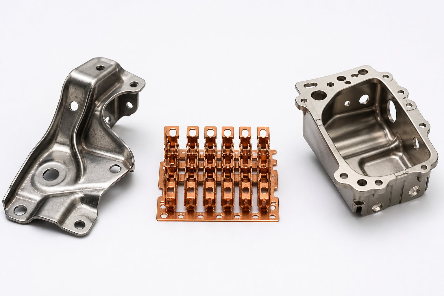
A stamping die that performs flawlessly for an automotive bracket might be entirely wrong for an aerospace sensor housing or a miniature connector pin. The forming operations themselves are universal, but the materials, volumes, quality systems, and tolerances each industry demands reshape how those operations are applied. Knowing where your parts land on this spectrum helps you specify requirements accurately and evaluate whether a supplier genuinely understands your sector's expectations.
Automotive Stamping Die Requirements
Automotive is the volume king. Structural reinforcements, body panels, transmission components, and brake assemblies run in the hundreds of thousands to millions of units per year. That scale drives everything about automotive stamping dies: the tooling must survive tens of millions of press cycles, the process must maintain consistency across multi-year production runs, and quality systems must satisfy IATF 16949 certification.
IATF 16949 is not a paper exercise. It requires suppliers to implement Advanced Product Quality Planning (APQP), conduct Production Part Approval Process (PPAP) submissions, and maintain documented corrective action systems. For engineers and procurement teams sourcing custom metal stampings in the automotive space, this means your supplier needs living process documentation, real-time SPC monitoring, and demonstrated Cpk values of 1.33 or higher on critical dimensions.
Material demands center on high-strength low-alloy steels, dual-phase steels, and increasingly, aluminum alloys for weight reduction. Steel stamping dies for automotive structural parts must account for aggressive springback in advanced high-strength steels, sometimes requiring multi-physics simulation to pre-compensate die geometry. Aluminum stamping dies face different challenges: galling, lower formability limits, and surface sensitivity that rules out the aggressive lubricant strategies common with steel.
An automotive stamping die also lives under constant pressure for cycle time optimization. Every second shaved from a press cycle multiplies across millions of parts. Progressive dies dominate this sector for smaller components, while transfer dies handle larger structural pieces and deep-drawn body elements.
Electronics and Connector Industry Demands
Electrical metal stamping occupies the opposite end of the size spectrum. Connector pins, shielding cans, lead frames, and contact springs involve features measured in tenths of millimeters, stamped from materials as thin as 0.1 mm. The tolerances here routinely reach ±0.025 mm on critical contact dimensions, and the materials, phosphor bronze, beryllium copper, and thin copper alloys, behave very differently from the steels and aluminums of automotive work.
Precision at this scale demands sub-micron punch-to-die clearances, servo-driven presses with micron-level repeatability, and 100% vision inspection systems that verify every part against CAD geometry. Progressive dies dominate because connector components run in volumes of millions to tens of millions per year, and the parts are small enough to remain on a carrier strip through all forming stations.
The challenge with electrical metal stamping is not brute force but control. Beryllium copper, a common material for spring contacts due to its conductivity and fatigue resistance, is notoriously difficult to form without micro-cracking. Phosphor bronze, while more forgiving, still demands precise management of grain direction and bend radii. These materials also tend to work-harden quickly, limiting the number of forming operations possible without intermediate annealing.
Die designers for the electronics sector also face miniaturization pressure. As devices shrink, connector pitches tighten, and the features stamped into lead frames and contact arrays become finer. According to industry data from precision stamping manufacturers, micro-stamped components below 0.1 mm thickness require wire EDM and micro-grinding techniques that achieve punch and die clearances in single-digit micron levels, pushing the boundaries of conventional tool-making.
Aerospace and High-Reliability Applications
Aerospace flips the volume equation. Production runs might range from 500 to 50,000 units, but every single part carries full traceability from raw material lot through final inspection. AS9100 certification, which builds upon ISO 9001 with more stringent requirements, demands documented procedures for material storage, heat treatment records, chemical composition analysis, and retention of quality records for seven or more years.
Materials in aerospace stamping are often exotic: titanium alloys, Inconel, precipitation-hardened stainless steels, and specialized aluminum grades like 6061 and 7075. These alloys resist forming, wear tooling faster, and require careful process parameter control to avoid micro-cracking or residual stress that could compromise fatigue life in flight-critical applications. Die designers must factor in limited formability windows, often requiring more generous bend radii, additional forming stages, and post-forming stress relief operations.
316/316L custom metal stamping also appears in aerospace sensor housings and fluid handling components where corrosion resistance is essential. The austenitic stainless grades work-harden significantly during forming, requiring dies with optimized clearances and careful attention to sequencing operations to avoid premature material failure.
Inspection protocols go well beyond SPC sampling. First-article inspection with full CMM reporting, functional testing under simulated operating conditions, and dimensional verification on every lot are standard expectations. The cost-per-part is secondary to documented proof that every component meets specification.
Consumer products occupy yet another zone: moderate volumes, cosmetic surface finish requirements, varied materials ranging from stainless to aluminum to pre-plated metals, and intense time-to-market pressure. Die design here prioritizes fast turnaround, flexible tooling approaches, and surface protection strategies that prevent scratches or marks on visible faces. Quality systems are typically ISO 9001 rather than sector-specific certifications, but finish standards can be more visually demanding than anything aerospace requires.
| Industry | Typical Materials | Volume Range | Key Certifications | Critical Tolerances |
|---|---|---|---|---|
| Automotive | HSLA steel, dual-phase steel, 5000/6000-series aluminum | 100K - millions/year | IATF 16949, ISO 9001 | ±0.05 mm to ±0.1 mm on structural features |
| Electronics | Phosphor bronze, beryllium copper, thin copper alloys | Millions - tens of millions/year | ISO 9001, IPC standards | ±0.025 mm on contact dimensions |
| Aerospace | Titanium, Inconel, 316/316L SS, 6061/7075 aluminum | 500 - 50,000/year | AS9100, NADCAP | ±0.025 mm to ±0.05 mm with full traceability |
| Consumer Products | 304 stainless, aluminum, pre-plated steel | 10K - 500K/year | ISO 9001 | ±0.1 mm dimensional; cosmetic finish critical |
These differences are not academic. They directly shape which suppliers qualify for your work, what inspection documentation you should expect with deliveries, and how your die design must be adapted to serve materials and standards specific to your sector. An automotive stamping die supplier without IATF 16949 is a non-starter for Tier 1 programs. An electronics die maker without micro-stamping capability and vision inspection cannot deliver the precision connector components require.
Regardless of industry, one question unifies all buyers: how tight can the tolerances actually be, and what quality systems ensure those tolerances hold across production volume?
Tolerances and Quality Standards in Precision Die Stamping
Tolerance numbers on a print mean nothing if the process behind them cannot hold those values part after part, shift after shift. Precision die stamping is capable of remarkably tight dimensional control, but what you can actually achieve depends on a chain of variables: material properties, die condition, press mechanics, and the quality infrastructure supporting it all. Knowing where those boundaries sit helps you specify tolerances that are achievable without paying for precision you do not need.
Achievable Tolerances in Custom Die Stamping
What used to be a standard tolerance of ±0.005 in. (±0.127 mm) in the stamping industry has progressively tightened. Today, precision die and stamping operations routinely hold ±0.002 in. (±0.05 mm) on critical features, with some applications reaching ±0.001 in. (±0.025 mm). Electronics connectors and micro-stamped lead frames push even further, operating in the sub-0.025 mm range where punch-to-die clearances drop to single-digit microns.
These numbers are real, but they come with conditions. Holding ±0.001 in. requires a precision die built with robust tool frames, oversized guide systems, and tight pilot clearances. When a stamper uses 0.0005 in. pilot clearance, the total variation in part dimensions stays within that same 0.0005 in. window, which is why custom precision stamping tooling must be engineered with repeatability in mind from the first CAD sketch.
Achievable precision also depends on feature type. Flat blanking and piercing dimensions are easier to hold tightly than bend angles or drawn depths, where springback and material flow introduce additional variables. Buyers should specify their tightest tolerances only on functionally critical features and allow standard manufacturing tolerances elsewhere to keep tooling cost reasonable.
What ISO 9001 and IATF 16949 Mean for Your Parts
Certifications get listed on supplier websites, but what do they actually require behind the scenes?
ISO 9001 is the baseline. It applies to any industry and establishes a Quality Management System built on documented processes, internal audits, management review, and corrective action systems. For precision die stamping buyers, ISO 9001 means your supplier has formalized their process controls and can demonstrate continual improvement. It does not, however, mandate specific inspection frequencies, capability indices, or traceability depth.
IATF 16949 builds directly on ISO 9001 and adds automotive-specific requirements for defect prevention, supply chain quality, and full part traceability. In practice, this means Advanced Product Quality Planning (APQP), Production Part Approval Process (PPAP) submissions, mandatory Cpk values of 1.33 or higher on critical dimensions, and formal warranty tracking. A Cpk of 1.33 effectively cuts your tolerance band in half from a practical standpoint, because it requires the process to be centered and capable well within specification limits.
AS9100 serves aerospace with even more stringent documentation. It demands full material traceability, retention of quality records for seven or more years, and documented procedures for nonconformance handling. Every lot must be traceable back to raw material origin, heat treatment records, and inspection results.
The practical takeaway: match your certification requirement to your industry. ISO 9001 is sufficient for general industrial and consumer applications. IATF 16949 is non-negotiable for automotive supply chains. AS9100 is mandatory for flight-critical components. Asking for more than you need adds cost without adding value to your parts.
Inspection Methods and Statistical Process Control
Even a perfectly designed precision die will drift over time. Punch edges wear, guide pins develop play, and material lots vary subtly in thickness or hardness. The inspection infrastructure surrounding the press is what catches drift before it becomes defective product.
High-performing stampers use a layered inspection approach:
- First-article inspection (FAI) validates a new setup against the drawing before production begins. Every critical dimension is measured and documented.
- In-process sampling pulls parts at defined intervals during the run. Critical features are measured with calipers, micrometers, or optical systems depending on tolerance requirements.
- Coordinate Measuring Machines (CMM) handle complex 3D geometries where manual gauging cannot reach. CMMs verify overall dimensions, hole locations, bend angles, and flatness on sampled parts.
- Optical and vision measurement systems provide non-contact verification ideal for thin or delicate stampings. High-speed camera systems can perform 100% inspection on micro-stamped parts at production speed.
- Statistical Process Control (SPC) tracks dimensional measurements over time, plotting trends and detecting process drift before parts leave tolerance. SPC charts reveal whether a process is stable and capable, not merely whether individual parts pass or fail.
SPC deserves special attention. A single measurement confirms one part. SPC confirms that your precision die stamping process is inherently capable of producing conforming parts over extended runs. It shifts quality from detection to prevention, which is exactly what high-volume buyers need.
Even with this infrastructure in place, tolerances degrade over production runs if the root causes are not managed. The most common factors that erode precision over time include:
- Punch and die edge wear, which gradually increases clearances and burr height
- Guide pin and bushing wear, allowing upper-to-lower die misalignment to develop
- Die shoe flexion under repeated tonnage, especially in undersized or thin shoe designs
- Material lot variation in thickness, hardness, or surface condition between coil changes
- Press ram deflection or gibbing wear that introduces positional drift
- Lubrication breakdown, increasing friction and altering material flow during forming
- Thermal expansion during extended high-speed runs, shifting clearances as die components heat up
A proactive maintenance program, sharpening cutting edges on schedule, verifying alignment periodically, and monitoring SPC trends for early warning signs, is what separates suppliers who hold precision over millions of cycles from those who start strong and gradually drift out of tolerance.
Tolerance capability and quality systems tell you whether a supplier can make your part correctly. The next question is equally practical: what will it cost, and how does volume change the economics?
Cost Drivers and Volume Economics for Custom Die Stamping
Here is the question that shapes every tooling decision: at what point does the upfront investment in a custom die pay for itself? The answer is not a single number. It depends on a stack of variables, from how complex your die is to how many parts you plan to run over its lifetime. Understanding each cost lever gives you the framework to compare stamping against alternatives and negotiate with suppliers from a position of knowledge rather than guesswork.
Primary Cost Drivers in Custom Die Projects
The price tag on a custom die is not arbitrary. It reflects measurable engineering and manufacturing inputs. Here are the factors that move the needle most:
- Die complexity - the number of stations in a progressive die, the tightness of tolerances, and the number of distinct forming operations all drive design hours and machining time. A four-station die costs far less than a sixteen-station die performing blanking, piercing, multiple bends, and in-die tapping.
- Stamping die steel and inserts - tool steel grade matters. A die built from D2 or A2 tool steel for moderate runs costs less than one using S7 or M2 high-speed steel for extended life. Carbide stamping dies, which use tungsten carbide inserts at high-wear punch and die sections, last significantly longer but increase tooling cost by 30-50%. The choice depends on your total production volume: carbide pays for itself over millions of cycles where standard tool steel would require multiple resharpenings or replacements.
- Part material costs - raw material typically represents 60-70% of a stamped part's total cost. Exotic alloys like beryllium copper or Inconel cost multiples more per kilogram than mild steel, and they wear tooling faster, compounding the expense.
- Press tonnage requirements - larger or thicker parts need bigger presses with higher operating costs per hour. A machine die rated at 200 tons runs cheaper per stroke than one requiring 600 tons of force.
- Secondary operations - heat treating, plating, deburring, tapping, or assembly steps performed after stamping add per-piece cost. Integrating some of these into the die itself (in-die tapping, for example) raises tooling cost but often lowers total part cost by eliminating handling and setup for separate operations.
Tool & die manufacturing is fundamentally a precision machining exercise. The die must be CNC-milled, wire-EDM cut, ground, and hand-fitted, all in hardened steel or carbide. Every hour of that skilled work shows up in the tooling quote. But that cost is fixed. It does not change whether you stamp 10,000 parts or 10 million.
Volume Thresholds Where Custom Tooling Pays Off
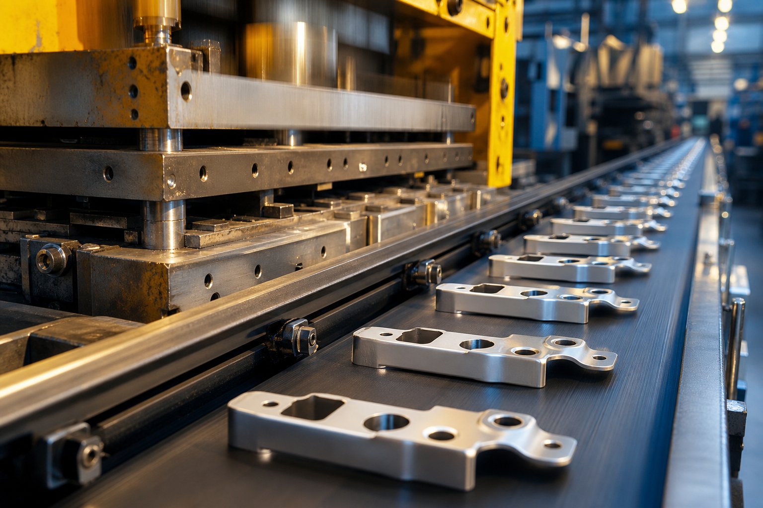
Custom stamping parts carry two cost layers: the one-time tooling investment and the per-piece production cost. At low volumes, the tooling cost dominates your per-unit economics. At high volumes, it becomes negligible per part and the low per-piece stamping cost takes over.
Consider a practical example. A custom progressive die costing $25,000 that produces a part at $0.12 each looks expensive if you only need 1,000 parts ($25.12 per unit with tooling amortized). At 100,000 parts, tooling adds only $0.25 per unit, bringing total cost to $0.37. At 1,000,000 parts, tooling contribution drops to $0.025 per unit, and your total cost is roughly $0.145 per part. CNC machining that same geometry might run $3.00-$5.00 per piece regardless of volume, because each part requires individual machine time.
According to production economics data from metal fabrication comparisons, the crossover point where stamping becomes cheaper than CNC machining typically falls between 5,000 and 20,000 parts, depending on part complexity and die cost. For simpler geometries with lower tooling investment, the break-even arrives earlier. For highly complex metal stamping die sets with many stations, it may take higher volumes to recoup the tooling expenditure.
The general volume framework from industry tooling guides breaks down like this:
| Volume Tier | Custom Die Stamping | CNC Machining | Laser Cutting | Casting |
|---|---|---|---|---|
| Under 1,000 parts | Uneconomical (tooling cost dominates) | Cost-effective; no tooling needed | Cost-effective for flat 2D profiles | Moderate (pattern/mold investment required) |
| 1,000 - 10,000 parts | Viable with simplified soft tooling | Still competitive but per-unit cost unchanged | Competitive for simple geometries only | Becoming cost-effective for 3D shapes |
| 10,000 - 100,000 parts | Clear cost advantage; hardened steel tooling justified | Expensive (high cumulative machine time) | Impractical for formed parts at this volume | Competitive for complex 3D geometries |
| Over 100,000 parts | Dominant choice; lowest per-unit cost by wide margin | Prohibitively expensive per part | Not scalable | Competitive only for very complex castable shapes |
The key insight: do not evaluate tooling cost in isolation. Evaluate total program cost across your forecasted lifetime volume, including reorders. Metal stamping die sets paid off in year one continue producing value for years afterward with only maintenance costs, making them appreciating assets rather than one-time expenses.
Lead Time Expectations and What Influences Turnaround
Cost is only half the equation. The other half is time. Custom die stamping projects follow a sequential development path, and each stage has a duration range that depends on complexity:
- Design validation and CAE simulation - 1 to 3 weeks. Includes feasibility review, forming simulation, and strip layout optimization.
- Detailed die design - 2 to 4 weeks. Full CAD modeling of all die components, bill of materials, and design review with the customer.
- Die manufacturing - 4 to 10 weeks. CNC machining, wire EDM, grinding, heat treatment of tool steel components, and carbide insert fabrication. This is the longest phase and scales directly with die complexity.
- Assembly and fitting - 1 to 2 weeks. Hand-fitting components, verifying alignments, and assembling the complete die set.
- Trial runs (T1 sampling) - 1 to 2 weeks. First samples are stamped, measured, and compared against specifications. Some manufacturers achieve T1 in as few as 4-5 weeks for moderately complex dies by overlapping design and machining phases.
- Revisions and re-trials - 1 to 3 weeks if adjustments are needed. Most dies require at least one round of fine-tuning after initial trials.
Total lead time for a typical custom progressive die ranges from 10 to 20 weeks, with simpler compound dies arriving faster (6-10 weeks) and complex transfer dies taking longer (12-20+ weeks).
What accelerates or delays this timeline? A few factors stand out. Complete and frozen part designs prevent revision loops. Early material specification allows the die designer to finalize clearances and compensation strategies without waiting for decisions. Suppliers with in-house wire EDM, CNC, and grinding eliminate subcontracting delays. And realistic tolerance specifications avoid unnecessary precision that adds machining time to every die component.
The most common buyer mistake is underestimating revision cycles. A die that requires three trial-and-adjust iterations instead of one can add four to six weeks beyond the original estimate. Front-loading engineering effort through simulation and DFM review is the most reliable way to compress lead time without cutting corners on quality.
Understanding these economics helps you budget and plan. But the cost framework only tells you what to expect. The workflow that actually delivers your die, from first feasibility check through production approval, determines whether those expectations become reality.
The Custom Die Stamping Workflow from Design to Delivery
Knowing the economics is one thing. Watching a die actually come to life, from a 3D model on a screen to hardened steel producing finished parts at speed, is where most buyers encounter surprises. The workflow is sequential and gate-driven: each stage must pass before the next begins, and skipping steps almost always costs more time than it saves. Whether your project involves a straightforward compound die or a complex progressive tool with twenty stations, the development arc follows the same fundamental structure.
Here is the complete sequence most metal stamping tooling projects follow:
- Feasibility assessment - Can this part be stamped at all?
- CAE simulation - Predict forming behavior, identify risks, optimize geometry digitally.
- Detailed die design - Full CAD modeling of every component, station layout, and strip progression.
- Die manufacturing - CNC machining, wire EDM, grinding, and heat treatment of tool steel components.
- Assembly and fitting - Hand-fitting, alignment verification, and complete die set assembly.
- Trial runs (T1 sampling) - First parts stamped, measured, and compared against specifications.
- Adjustments and re-trials - Fine-tuning based on dimensional data from initial samples.
- Production approval - Formal sign-off that the die meets all requirements for volume production.
- Ongoing maintenance - Scheduled preventive care and stamping tool repair to preserve precision over millions of cycles.
Each gate carries specific deliverables and decision points. Understanding what happens at each stage, and what questions to ask, prevents the surprises that derail timelines and budgets.
Feasibility Assessment and CAE Simulation
The workflow begins before any steel is cut or any CAD file is opened for die design. Feasibility assessment answers a deceptively simple question: can this part geometry be produced through stamping given the specified material, thickness, and tolerances?
An experienced stamping tool and die engineering team evaluates your part for formability constraints, material flow challenges, and potential defect risks. They look at draw depth ratios, bend radii relative to material thickness, feature spacing, and whether the part can be produced in a single die or requires multiple stages. This is where impractical geometries get flagged early. A feature that works perfectly in CNC machining might be impossible to stamp without cracking, or might require an additional forming station that changes the project economics entirely.
Questions to ask at this stage: Has the supplier identified any features that push beyond standard formability limits? Are there alternative geometries that achieve the same function with better manufacturability? What die type do they recommend and why?
Once feasibility confirms the part is stampable, CAE simulation takes over. Using finite element analysis software like AutoForm or DEFORM, engineers digitally replicate the entire forming process before committing to physical tooling. According to CAE simulation specialists in stamping die engineering, this step allows prediction of material flow behavior, stress and strain distribution, thickness variation, wrinkling tendencies, and springback deformation, all before a single dollar is spent on die manufacturing.
The simulation stage is where the traditional "Design, Manufacture, Tryout, Fix, Repeat" cycle gets compressed into "Design, Simulate, Optimize, Manufacture, Minimal Tryout." Manufacturers who leverage CAE typically reduce tryout iterations by 30-50%, which translates directly into weeks saved and fewer costly die modifications. Forming Limit Diagrams (FLDs) identify crack-risk zones, thinning maps reveal where material might fail, and springback compensation is calculated mathematically rather than discovered through physical trial and error.
For buyers, the practical benefit is straightforward: a supplier who simulates before machining delivers dies that work closer to right the first time. Skipping simulation to save a week upfront often costs three to six weeks in trial-and-adjust cycles downstream.
Die Design, Machining, and Assembly
With simulation data validating the forming approach, detailed die design begins. This is full-scale CAD modeling of every component: punch profiles, die blocks, strippers, pilots, guide systems, spring elements, and the die shoe structure that holds everything in alignment under tonnage. For progressive dies, the strip layout is finalized here, defining the pitch (advancement per stroke), station sequence, and scrap bridge design.
A custom metal stamping tool at this stage is not a single part but an assembly of dozens to hundreds of precision components, each toleranced to work together under dynamic load. The design phase typically takes two to four weeks and should include a formal design review where the buyer verifies critical dimensions, material callouts, and any changes from the original part geometry.
Die manufacturing is the longest phase in the workflow, running four to ten weeks depending on complexity. The core processes include:
- CNC milling - roughing and semi-finishing die blocks, punch holders, and structural components from tool steel billets.
- Wire EDM - cutting precise punch and die profiles, especially for complex contours and tight internal corners that milling cannot reach.
- Surface grinding - achieving flatness and parallelism on mating surfaces, critical for die alignment and consistent shut height.
- Heat treatment - hardening tool steel components to their working hardness (typically 58-62 HRC for cutting punches), then tempering to balance hardness with toughness.
- Finish grinding and polishing - final dimensioning of hardened components and surface preparation for forming areas where material flow must be smooth.
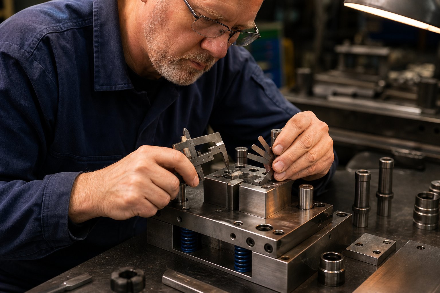
Assembly and fitting follow machining. Even with CNC precision, stamping tooling components require hand-fitting by skilled die makers who verify punch-to-die clearances, check alignment under simulated press conditions, and ensure all moving elements (strippers, knockout pins, pilots) operate freely without binding. This phase typically takes one to two weeks and concludes with a bench tryout to confirm mechanical function before the die goes on-press.
Trial Runs, Inspection, and Production Approval
The first press trial, often called T1 sampling, is the moment of truth. The die is mounted in a press matching the tonnage and shut height specifications from the design phase, and the first parts are stamped. Engineers measure every critical dimension on these samples against the part print, documenting deviations and identifying which die stations need adjustment.
Rarely does a T1 trial produce perfect parts on the first stroke. Typical adjustments include fine-tuning punch penetration depth, modifying springback compensation on bending stations, adjusting blankholder pressure, and shimming stations where dimensions run slightly off-target. Experienced die builders plan for this iteration, treating T1 as a validation step rather than expecting production-ready results immediately.
A second trial (T2) confirms that adjustments resolved the deviations found in T1. For complex dies, a T3 may be needed. Each round narrows the gap between actual parts and target specifications until all dimensions fall within tolerance. The front-loaded CAE simulation work described earlier is what keeps this iteration loop short. Without simulation, three to five physical iterations are common. With it, most dies reach approval in one or two rounds.
Production approval is the formal gate where measured parts, statistical data, and process parameters are documented and signed off. For automotive programs, this takes the form of PPAP submission. For aerospace, it means a full first-article inspection report with traceability records. For general industrial parts, approval may simply be a dimensional report confirming all features pass.
Beyond approval, the die enters its production life, and maintenance becomes the critical factor in sustaining quality. Preventive maintenance on a defined schedule, inspecting punch edges for wear, verifying guide alignment, replacing elastic elements, and re-applying PVD coatings on forming surfaces, keeps tolerances stable across hundreds of thousands or millions of cycles. Stamping tool repair becomes necessary when preventive measures reveal components approaching end-of-life: worn punches are reground or replaced, guide bushings are renewed, and active surfaces are recoated. A structured maintenance program, whether preventive or extraordinary, reduces scrap rates, prevents unplanned downtime, and extends die life well beyond initial projections.
Suppliers offering this end-to-end workflow under one roof eliminate the coordination risk that comes with splitting feasibility, design, machining, and tryout across multiple vendors. YICHEN's stamping die solutions illustrate this full-process model in practice: feasibility analysis and CAE simulation feed directly into in-house die machining, trial runs, and dimensional inspection, giving manufacturers a single point of accountability from initial concept through production-ready tooling. For teams moving from early research toward an RFQ, this integrated approach compresses communication loops and keeps timelines predictable.
A well-executed workflow delivers a die that runs reliably. But the workflow is only as strong as the partner executing it, which raises a final practical question: how do you evaluate whether a supplier can actually deliver on the process they describe?
How to Choose the Right Custom Die Stamping Partner
Every stamping die manufacturer can show you a list of machines. Fewer can walk you through how they would solve your specific forming challenge before quoting a price. That difference, between a vendor who fills orders and a partner who engineers solutions, determines whether your project hits production on schedule or stalls in revision cycles. Here is how to separate the two.
Technical Capability Criteria to Evaluate
When reviewing metal stamping die manufacturers, start with what they can actually do rather than what their website claims. A metal stamping dies company overview tells you their story. Their equipment list, engineering team, and project history tell you whether they can handle your part.
Use this checklist to structure your evaluation:
- Press tonnage range - Does their equipment match your part size and material thickness? A supplier with only small presses cannot produce deep-drawn automotive components.
- In-house die design and CAE simulation - Suppliers who design and simulate internally catch problems before machining begins. Outsourced design adds communication gaps and lead time.
- Die complexity experience - Ask for examples of similar part geometries. A stamping dies manufacturer experienced with 20-station progressive dies operates at a different level than one building simple blanking tools.
- Quality certifications - Match certifications to your industry: ISO 9001 for general applications, IATF 16949 for automotive, AS9100 for aerospace. Verify them rather than taking a supplier's word.
- Trial and prototyping capability - Can they run T1 samples in-house and provide full dimensional reports? Suppliers who subcontract trial runs lose control over iteration speed.
- Material expertise - Confirm they have run production in your specific alloy. A die manufacturer experienced with mild steel may struggle with phosphor bronze or high-strength dual-phase grades.
- Geographic and logistic fit - Consider shipping costs, time zone overlap for communication, and IP protection frameworks in the supplier's jurisdiction.
- Transparent quoting - A detailed quote breaks out tooling, piece price, material, and secondary operations separately. Vague lump-sum quotes make it impossible to compare suppliers fairly or identify cost-reduction opportunities.
Common Buyer Mistakes to Avoid
After reviewing hundreds of RFQs, experienced metal stamping die manufacturers consistently flag the same buyer errors that inflate costs or delay projects:
Underspecifying tolerances. Marking every dimension as critical forces the die manufacturer to build precision into features that do not need it. Identify which features are functionally critical and allow standard tolerances elsewhere.
Omitting material specifications. Saying "stainless steel" without specifying 304 versus 316 versus 430 leaves the supplier guessing. Each grade forms differently and requires different die clearances. As RFQ best-practice guides emphasize, exact material grade is one of the most common missing details that delays quoting by days.
Choosing solely on price. The cheapest stamping die factory quote often reflects shortcuts: thinner die shoes, lower-grade tool steel, or skipped simulation steps. Those savings reappear as longer tryout cycles, premature die wear, and inconsistent parts once production ramps.
Not requesting trial run data. Ask for T1 sample dimensional reports and process capability data from similar past projects. A supplier who cannot provide this either does not measure rigorously or does not retain records, both red flags for production consistency.
Moving from Research to RFQ-Ready Engagement
You have read through process types, forming operations, industry standards, cost drivers, and workflow stages. The gap between research and action is a well-structured RFQ sent to a qualified partner. Prepare a complete package: 3D CAD file plus dimensioned PDF, exact material grade, annual volume forecast, tolerance callouts on critical features, surface finish or coating requirements, and your target timeline.
For manufacturers and sourcing managers looking for a stamping die manufacturers partner that covers feasibility analysis, CAE simulation, die machining, trial runs, and final inspection under one roof, YICHEN's stamping die solutions offer that full-spectrum capability. Their integrated model lets you move from initial concept discussion to an RFQ-ready custom stamping die solution without coordinating across multiple vendors, compressing both communication overhead and development timelines.
The best supplier relationship starts with clarity on both sides. Define what you need precisely, evaluate partners on engineering depth rather than price alone, and choose a metal stamping die manufacturer whose workflow, certifications, and communication style align with how your team operates. That alignment is what turns a tooling purchase into a production advantage.
Custom Die Stamping FAQs
1. What is the difference between custom die stamping and standard die stamping?
Standard die stamping uses pre-existing tooling to produce generic shapes like washers or simple brackets. Custom die stamping involves engineering tooling from scratch for a specific part geometry, material, and tolerance requirement. The custom approach lets your part design drive the tooling rather than forcing design compromises to fit available dies. While standard dies have zero upfront cost, custom tooling amortizes across production volume and delivers significantly lower per-unit costs at scale, typically breaking even between 5,000 and 20,000 parts depending on complexity.
2. How much does custom die stamping tooling cost?
Custom die tooling typically ranges from $8,000 to $50,000 or more depending on complexity factors like number of stations, tolerance requirements, tool steel grade, and whether carbide inserts are needed. A four-station progressive die costs far less than a sixteen-station die performing blanking, piercing, multiple bends, and in-die tapping. However, this upfront investment amortizes over every part produced. For example, a $25,000 die producing 1,000,000 parts adds only $0.025 per unit in tooling cost, making it dramatically cheaper than CNC machining at volume.
3. What tolerances can custom die stamping achieve?
Modern precision die stamping routinely holds ±0.002 in. (±0.05 mm) on critical features, with some applications reaching ±0.001 in. (±0.025 mm). Electronics micro-stamping pushes even further into sub-0.025 mm territory. Achievable precision depends on feature type, material, die condition, and press characteristics. Flat blanking and piercing dimensions are easier to hold tightly than bend angles or drawn depths. Suppliers like YICHEN use CAE simulation and SPC monitoring to maintain these tolerances consistently across high-volume production runs.
4. How long does it take to get a custom stamping die built?
Total lead time for a typical custom progressive die ranges from 10 to 20 weeks. This includes feasibility assessment (1-3 weeks), detailed die design (2-4 weeks), die manufacturing via CNC, wire EDM, and grinding (4-10 weeks), assembly and fitting (1-2 weeks), and trial runs with adjustments (2-5 weeks). Simpler compound dies arrive faster at 6-10 weeks, while complex transfer dies may take 12-20 weeks. Front-loading engineering effort through CAE simulation and complete part specifications is the most reliable way to compress timelines.
5. What types of custom stamping dies are available and how do I choose?
Four main types serve different needs. Progressive dies carry a strip through multiple stations for high-volume small-to-medium parts. Transfer dies move discrete blanks between stations for large or deep-drawn components. Compound dies perform multiple cutting operations simultaneously for flat parts with superior precision. Fourslide dies use multi-directional slides for complex bends on small parts. Selection depends on annual volume, part dimensions and depth, geometric complexity, material thickness, and tolerance requirements. A qualified partner like YICHEN evaluates these factors during feasibility assessment to recommend the optimal die type for your specific application.


