


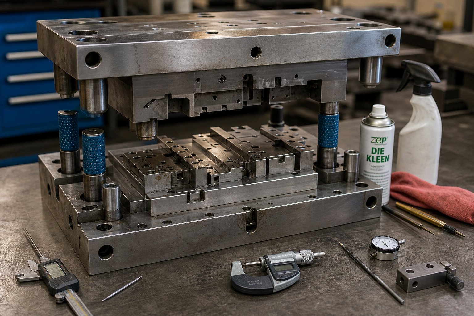
What Stamping Die Maintenance Means for Production Teams
You already know the die is the heartbeat of your stamping operation. When it runs well, parts flow, schedules hold, and nobody gets a phone call at 2 a.m. When it doesn't, everything downstream pays the price. The real question isn't whether maintenance matters - it's whether your program is actually structured to prevent failures or just fast enough to react to them.
What Stamping Die Maintenance Actually Involves
Stamping die maintenance is the systematic process of inspecting, cleaning, sharpening, replacing worn components, and verifying alignment to preserve die function and extend productive life between failures.
That definition covers the full scope, but each element carries real weight on the shop floor. Inspection means more than a quick visual pass - it includes measuring punch-to-die clearance, checking guide pin wear, and identifying early signs of galling or edge chipping before they produce scrap. Cleaning removes slug buildup, hardened lubricant residue, and debris that accelerate wear. Sharpening and reconditioning restore cutting geometry and maintain the tolerances your parts require. Component replacement addresses springs, pilots, bushings, and other wear items on a schedule rather than after failure. Alignment verification confirms that shut height, timing, and station-to-station registration remain within spec.
These aren't isolated tasks. They form a systematic approach where the quality of one step directly determines the reliability of the next. Skip the cleaning, and your inspection misses a hairline crack. Miss the crack, and your next production run ends with a broken punch and an unplanned four-hour stoppage.
Why Maintenance Programs Fail Without Structure
Most shops aren't neglecting their dies on purpose. The problem is that die maintenance often defaults to reactive repair - what the industry calls "firefighting." A punch chips, production stops, the technician swaps or resharpens it, and the press runs again. The immediate crisis is solved, but nothing about the underlying wear pattern, lubrication gap, or alignment drift gets addressed.
A key distinction from MetalForming Magazine frames this clearly: repair is restoring something broken to working condition, while maintenance is preserving something in its current state through scheduled upkeep. Many organizations track these together, which masks how much time and budget actually goes toward emergency fixes rather than prevention. Research consistently shows that a fully reactive approach costs 25-30% more than a structured preventive die maintenance program, largely due to emergency labor premiums, rush-ordered parts, and the cascading production losses that never appear on the maintenance budget line.
This article isn't a beginner's overview of why dies need attention. It's a working manual for tooling managers and die maintenance technicians who want to close the gap between chasing failures and preventing them - covering checklists, troubleshooting frameworks, material considerations, tracking systems, and the monitoring technologies that make condition-based scheduling practical.
The Business Case for Preventive Die Maintenance
Telling leadership that preventive maintenance "saves money" rarely moves the needle. Budgets get approved with numbers, not principles. The challenge for most tooling managers isn't believing in prevention - it's quantifying what prevention is actually worth in their specific operation. That requires a framework tied to your own production data, not generic industry claims.
A Framework for Calculating Die Maintenance ROI
The core logic is straightforward. Your die maintenance cost savings come from three value streams weighed against your total maintenance investment:
(Avoided Downtime Cost + Avoided Scrap Cost + Extended Die Life Value) - (Maintenance Labor + Parts + Tooling) = Net Maintenance ROI
Sounds simple, but the hard part is knowing where to pull each number in your shop. The table below maps each cost category to what you should measure and where that data typically lives.
| Cost Category | What to Measure | Where to Find It |
|---|---|---|
| Unplanned Downtime Cost | Hours of unscheduled press stoppage per month, multiplied by fully burdened hourly cost (lost revenue + idle labor + overhead) | Press downtime logs, production scheduling system, accounting cost-per-hour rates |
| Scrap and Rework Cost | Defective parts produced due to die condition issues (burrs, dimensional drift, surface defects), multiplied by material and labor cost per part | Quality system reject reports, scrap tracking logs, material cost sheets |
| Extended Die Life Value | Capital cost of die replacement deferred by maintaining current tooling longer (total die cost divided by expected life in strokes, compared to actual life achieved) | Tooling purchase records, die history cards, stroke counters |
| Maintenance Labor | Technician hours spent on scheduled preventive tasks (not reactive repair) | Work orders, time tracking, maintenance scheduling system |
| Parts and Consumables | Cost of replacement punches, springs, bushings, sharpening, and coatings consumed during planned service | Maintenance purchase orders, tool crib inventory records |
| Tooling and Equipment | Amortized cost of grinding equipment, measurement tools, and any die maintenance software or tracking systems | Capital equipment records, software subscription costs |
You'll notice the "avoided" costs require a baseline. If you're not already tracking unplanned downtime hours and scrap rates tied to die condition, start there. Even a month of clean data gives you a credible starting point for the calculation.
Hidden Costs of Reactive-Only Maintenance
The reason reactive die repair looks deceptively cheap is that shops typically only account for the direct fix - the replacement punch and the technician's hour. MetalForming Magazine illustrates this with a real scenario: a single broken punch that costs $25 to replace plus one hour of toolmaker labor appears to be a $50 event. In reality, it also generates one hour of setup labor to pull the die, another hour to reset it, 30 minutes of quality lab time, scrapped parts, idle operator wages, and management overhead. The actual cost for that one unplanned stop exceeds $500.
Multiply that pattern across dozens of events per month and the gap becomes clear. Unplanned maintenance can run four times more expensive than planned maintenance when you account for all the costs that vanish when die repair happens offline rather than mid-run. Those hidden multipliers - setup teardown, press idle time, quality re-verification, partial-run scrap, and the margin lost on parts never produced - are what make the ROI case compelling.
The path forward isn't simply spending more on maintenance. It's shifting the ratio of planned-to-unplanned work so that your investment goes toward preserving die condition rather than recovering from failures. When you can show leadership the fully burdened cost of a single unscheduled die pull versus the cost of a scheduled offline service, the stamping die downtime reduction pays for itself in the math alone.
Building this business case gives you the budget. The next question is how to deploy that budget effectively - which means defining exactly what gets inspected, measured, and serviced at each maintenance interval.
Structured Maintenance Checklists by Interval
A budget and good intentions don't keep dies running - repeatable actions do. The difference between a program on paper and one that actually prevents failures comes down to specificity: who checks what, how often, and against which measurable standard. A vague instruction like "inspect the die" leaves too much to interpretation. A well-built die maintenance checklist ties each task to a frequency, a measurement threshold, and a clear pass/fail criterion.
The intervals below are structured around the four tiers most production environments rely on - daily, weekly, monthly, and annual - plus stroke-count-based triggers that adjust for actual die workload rather than calendar time alone.
Daily and Weekly Inspection Tasks
Daily checks are your first line of defense. They're quick, visual, and designed to catch problems that developed during the previous run before they compound into scrap or unscheduled downtime. Think of these as the tasks every press operator or setup technician can handle without pulling the die from the press.
- Visual inspection of part quality: Check the first-off and in-run samples for burr formation, scratches, dimensional shifts, or surface marks. Any change from the previous run's baseline warrants investigation before continuing.
- Slug and debris removal: Clear trapped slugs, slivers, and loose scrap from the die cavity, scrap paths, and ejection areas. Trapped material is one of the most common causes of surface damage and misfeeds.
- Lubrication verification: Confirm that lubricant is reaching all intended application points - sprayers, rollers, and manual lube areas. Dry contact surfaces accelerate galling and edge wear far faster than most technicians expect.
- Fastener spot-check: Verify that accessible screws, clamps, and guards remain secure. Abnormal press noise during a run often traces back to a loosened retainer or shifted section.
- Scrap path clearance: Ensure slug chutes and scrap channels are flowing freely. Blockages cause slug stacking, which can crack punches or damage die sections.
Weekly tasks go a layer deeper. These typically require pulling the die to a bench or at minimum accessing components that aren't visible during production.
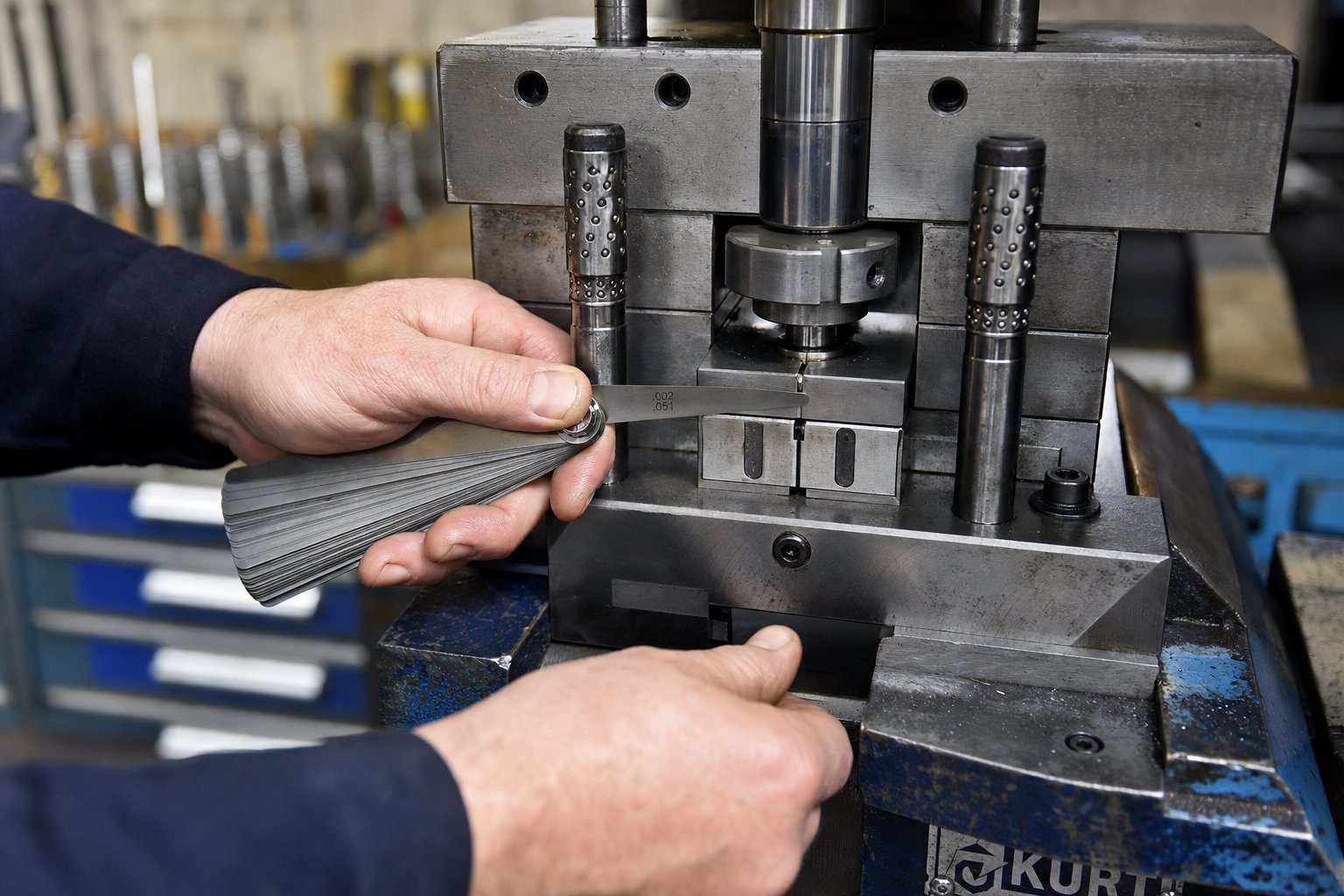
- Punch-to-die clearance measurement: Use feeler gauges to verify clearance at cutting stations. MISUMI's engineering guidance recommends clearance values as a percentage of material thickness per side, with harder materials requiring increased clearance. Any deviation beyond your documented tolerance - often flagged when clearance drifts more than 0.02 mm from specification - signals that shims need adjusting or components need replacement.
- Guide pin and bushing inspection: Check for scoring, excessive play, or rough motion. Clean and relubricate with 3-5 drops of precision oil, then manually cycle the guide assembly to confirm smooth travel.
- Spring condition assessment: Inspect springs for cracking, fatigue marks, or loss of free length. Industry guidelines suggest replacing any spring whose free length has decreased by more than 10%, as weakened return force leads to strip control issues and inconsistent stripping.
- Pilot and sensor check: Verify that pilots enter cleanly without one-sided contact. Confirm photoelectric sensors and proximity switches remain unobstructed and responsive.
- Alignment verification: Look for uneven witness marks on die shoes, heel blocks, and mating surfaces. Asymmetric wear patterns indicate mounting drift or press parallelism issues.
Monthly and Annual Maintenance Procedures
Monthly service windows are where preventive maintenance shifts from monitoring to active restoration. These intervals address the cumulative wear that daily and weekly checks can only flag.
- Sharpening and regrinding schedule: Evaluate cutting edges against documented wear limits. A common benchmark is to initiate regrind when edge wear exceeds 0.1 mm, but your threshold should reflect the part's burr tolerance and the die steel grade. Track cumulative stock removal from each regrind to monitor remaining tool life.
- Surface finish evaluation: Inspect forming stations, draw corners, and contact faces for galling, scratching, or surface roughness changes. Polish minor damage and document any areas trending toward failure.
- Component wear measurement: Measure critical dimensions on punches, die buttons, inserts, and bushings against their nominal specifications. Record actual measurements - not just "pass" or "fail" - so you can track wear rate trends over multiple service intervals.
- Deep cleaning: Disassemble sections that trap contamination and remove hardened lubricant, compacted fines, and corrosion. Clear lubrication channels and verify flow through all delivery points.
- Guide and pad assessment: Evaluate guide pins, bushings, shims, and pressure pads for cumulative wear that may not be obvious during weekly checks but compounds into alignment loss over time.
Annual service is your most comprehensive review - essentially a full health assessment that determines the die's trajectory for the coming production cycle.
- Full teardown and metrology review: Disassemble the die completely. Measure all critical dimensions, clearances, and surface conditions against original specifications or last die reconditioning baseline.
- Reconditioning evaluation: Determine whether accumulated wear across multiple components justifies a full reconditioning effort - restoring alignment, surfaces, clearances, and working accuracy across the entire tool - or whether targeted component replacements are sufficient.
- Replacement planning: Identify components approaching end-of-life and budget for replacements before they fail in production. Cross-reference sharpening history to assess remaining regrind capacity on cutting sections.
- Documentation update: Revise PM standards, inspection criteria, die prints, and training notes based on the year's maintenance history and any engineering changes to the part or process.
Setting Stroke-Count-Based Maintenance Triggers
Calendar intervals keep tasks from being skipped during busy weeks, but they don't account for how hard the die actually works. A die that ran 500,000 strokes last month needs very different attention than one that sat idle for three weeks and ran a short job. That's why the most effective stamping die inspection schedule layers stroke-count triggers on top of time-based intervals.
The concept is straightforward: define hit-count thresholds for key maintenance actions based on actual wear data, then use your press counter to trigger service when the die reaches each milestone. Industry best practice recommends using consistent hits-per-service intervals rather than arbitrary calendar dates, with thresholds set from actual service-life data for each die.
| Maintenance Action | Typical Stroke-Count Trigger Range | Adjustment Factors |
|---|---|---|
| Cutting edge inspection and sharpening review | Every 100,000-300,000 strokes | Tighten for high-strength steel, stainless, or abrasive materials; loosen for soft copper or aluminum |
| Spring replacement evaluation | Every 500,000-1,000,000 strokes | Shorten interval if springs show early fatigue or if stripping force is critical to part quality |
| Guide pin and bushing service | Every 250,000-500,000 strokes | Tighten for progressive dies with tight pilot clearances; loosen for simple blanking tools |
| Full teardown and reconditioning assessment | At 70-80% of expected die life | Use cumulative regrind history and dimensional trend data to refine timing |
Material type is one of the strongest variables affecting these thresholds. Stamping stainless steel or high-strength steel accelerates edge wear and increases galling risk, which may demand sharpening intervals at the lower end of the range - or even below it. Aluminum and copper alloys are gentler on cutting edges but can produce material buildup on die surfaces that requires more frequent cleaning. Production data from Metal Stampings reinforces this point: for high-volume lines or high-hardness materials, the maintenance cadence should increase accordingly.
The key is treating these trigger ranges as starting points, not fixed rules. After two or three service cycles, your own wear data will tell you whether to tighten or extend each interval for a specific die. That data-driven adjustment is what separates a generic checklist from a living inspection schedule that reflects how your dies actually wear in your production environment.
Checklists tell you what to look at and when. But when you find a problem - a burr that wasn't there yesterday, a dimension that's drifting, a slug that keeps pulling back - the next challenge is connecting that symptom to the right corrective action without guesswork.
Troubleshooting Symptoms and Root Cause Analysis
A part comes off the press with a burr that wasn't there two hours ago. Dimensions are drifting on a feature that held tolerance all week. Slugs keep riding back up into the die. Each of these tells you something specific about what's happening inside the tool - if you know how to read the signals. The difference between a quick fix and a recurring headache often comes down to whether you're treating the symptom or addressing the actual die condition behind it.
This section provides a structured stamping die troubleshooting guide that maps what you can see on the part or in the press directly to what's likely happening inside the die - and what to do about it.
Mapping Part Defects to Die Conditions
Most die-related defects fall into a handful of recognizable patterns. The trick is resisting the urge to jump straight to a fix before confirming the root cause. A burr, for example, might mean your cutting edge is dull - or it might mean your clearance shifted because a dowel pin loosened. The corrective action is completely different depending on which condition is actually present.
The table below connects the most common observable symptoms to their probable die conditions, the corrective stamping tool repair action required, and - critically - the prevention strategy that keeps the problem from returning.
| Observable Symptom | Probable Die Condition | Corrective Maintenance Action | Prevention Strategy |
|---|---|---|---|
| Excessive or uneven burrs on cut edges | Dull cutting edges, incorrect punch-to-die clearance, or tool misalignment | Resharpen cutting edges and verify edge geometry. Measure clearance at multiple points around the profile. Check alignment of punch to die opening. | Set stroke-count-based sharpening triggers. Monitor clearance at weekly intervals. Use full-guide die construction to maintain alignment. |
| Dimensional drift on hole locations or formed features | Worn guide pins or bushings, pilot wear, thermal expansion during extended runs, or loose die components | Measure guide pin-to-bushing clearance and replace worn components. Inspect pilots for diameter loss. Verify mounting hardware torque. Allow thermal stabilization before measuring. | Track dimensional trends across production runs. Replace bushings on a schedule based on wear-rate data. Standardize warm-up hit counts before first-article approval. |
| Slug pulling back into die (slug retention) | Vacuum condition in slug channel, insufficient punch penetration, excessive oil on slug face, die clearance too large, or spring fatigue on ejection components | Increase punch entry depth. Add vacuum-relief features or air passages. Clean and degrease slug path. Verify die clearance hasn't opened beyond specification. Replace fatigued springs. | Design slug chutes with taper to prevent stacking. Demagnetize punches regularly. Audit lubrication volume to prevent excess pooling. |
| Galling or material buildup on die surfaces | Inadequate lubrication at contact points, coating failure or wear-through, incompatible die material and workpiece combination, or excessive surface roughness on forming stations | Remove material buildup with non-abrasive methods (chemical stripping for coated dies, fine stoning for uncoated). Reapply or replace surface coating. Restore surface finish on affected areas. Adjust lubrication delivery. | Match lubricant type to workpiece material - stainless steel and aluminum are particularly prone to galling. Monitor coating condition monthly. Polish forming surfaces to maintain specified Ra values. |
| Edge chipping or fracture on punches or die sections | Impact damage from slug stacking, incorrect heat treatment resulting in excessive brittleness, misalignment causing off-center loading, or insufficient clearance creating excessive shear stress | Replace chipped components. Inspect mating components for secondary damage. Verify alignment with a test impression. Check clearance and shut height settings. Review heat treat certification on replacement parts. | Maintain proper clearance to reduce shear load on edges. Confirm heat treatment hardness falls within recommended range for the die steel grade (avoid over-hardening). Keep slug paths clear to prevent upward slug interference. |
| Surface scratches or scoring on formed parts | Trapped debris or metal chips in die cavity, damaged die surface, rough or worn forming areas, or contamination from environment | Clean die cavity thoroughly. Polish affected die surfaces. Remove and replace any components with permanent scoring. Check strip cleanliness and lubrication coverage. | Implement daily debris removal as part of end-of-run routine. Maintain clean working environment around the press. Schedule monthly surface-finish inspections on all forming stations. |
Root Cause Analysis for Common Failure Modes
The table gives you a fast diagnostic path, but recurring issues demand deeper investigation. When the same symptom keeps appearing after you've performed the corrective action, you're likely treating a secondary effect rather than the primary failure mode.
Imagine you're resharpening a punch every 50,000 hits when the expected interval is 200,000. The dull edge is real, but it's not the root cause - it's the result of something else. Maybe the clearance is set too tight, which increases cutting force and accelerates wear. Maybe the die steel hardness is too low for the workpiece material. Or maybe thermal buildup from inadequate lubrication is softening the edge during long runs.
A practical root cause approach for die repair and maintenance follows this sequence:
- Confirm the symptom is consistent: Is the defect on every part, every Nth part, or random? Consistent defects point to a fixed die condition. Intermittent ones suggest a dynamic issue like thermal cycling, strip feed variation, or spring fatigue that only manifests under certain load conditions.
- Isolate the station: In progressive dies, ink-mark or short-feed the strip to identify exactly which station produces the defect. Don't assume - verify.
- Measure before acting: Take clearance readings, dimensional measurements, and surface condition notes before you change anything. Without a baseline, you can't confirm whether your corrective action actually addressed the condition.
- Check upstream causes: A comprehensive review of stamping defect origins shows that material inconsistency, press parameter errors, and feed positioning problems frequently masquerade as die wear issues. Verify incoming material thickness and hardness. Confirm press tonnage and shut height haven't drifted. Rule out strip feed pitch errors before pulling the die for service.
- Document and compare: Record what you found, what you changed, and what happened next. Over time, this history becomes your most reliable troubleshooting resource - revealing patterns that no single inspection could catch.
This structured diagnostic approach replaces guesswork with evidence. Instead of swapping parts until the problem goes away, you're building a cause-and-effect record that makes each future diagnosis faster and more accurate.
Of course, how a die wears - and how quickly - isn't only a function of maintenance timing. The materials the die is made from, the coatings applied to its surfaces, and the lubricants used during production all shape the wear pattern itself, which means they directly influence what shows up in your troubleshooting table and how often you'll need to act on it.
Die Materials and How They Shape Maintenance Needs
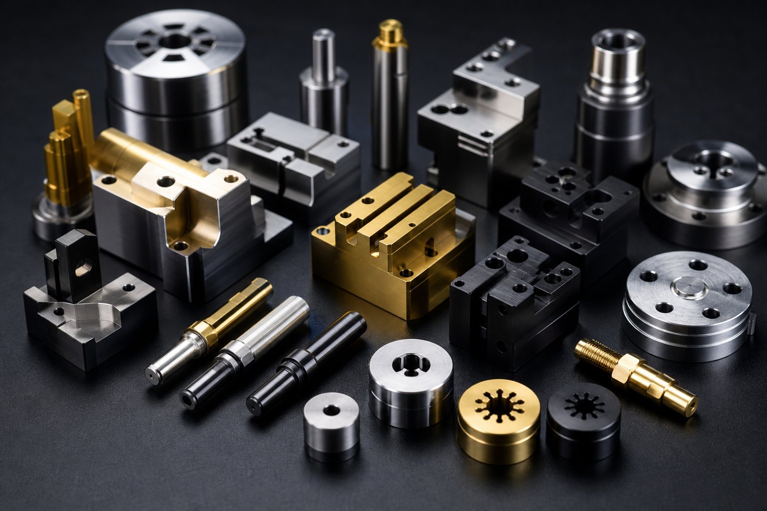
Every entry in your troubleshooting table - dull edges, chipping, galling - traces back to a material interaction. The steel grade in your die, the coating on its surface, and the lubricant between it and the workpiece form a system. Change any one variable and your maintenance frequency, your corrective actions, and your sharpening limits all shift. Understanding these die steel maintenance requirements lets you tailor your program to the actual tool rather than applying a one-size-fits-all schedule.
Tool Steel Grades and Their Maintenance Demands
The most common grades in stamping tooling each bring a distinct trade-off between wear resistance and toughness - and that trade-off dictates how you maintain them.
- D2 (High-Carbon, High-Chromium): With 11-13% chromium and a maximum hardness around HRC 62-65, D2 delivers superior wear resistance for long-run blanking and forming dies. The trade-off is brittleness - D2 is more susceptible to edge chipping under impact loads. Maintenance focus: monitor edges closely for micro-fractures rather than gradual dulling. Regrind intervals are longer, but when chipping occurs, the repair is more involved. D2 is also difficult to machine, so component replacement costs more than softer alternatives.
- A2 (Air-Hardened): A2 reaches HRC 62-65 with excellent abrasion resistance and better dimensional stability during heat treatment than oil-hardened grades. It's a workhorse for die shapes and slitters where wear resistance is critical. Maintenance focus: A2 resharpens predictably and tolerates more regrind cycles than D2 before dimensional limits are reached. Weekly clearance checks remain important because A2's fine grain structure masks gradual wear until part quality degrades.
- M2 (High-Speed Steel): Designed for high-speed cutting, M2 resists softening at elevated temperatures - maintaining its edge where friction generates heat during long production runs. Its maximum hardness reaches approximately HRC 65. Maintenance focus: M2 punches hold geometry well under heat but demand careful inspection for thermal fatigue cracks during monthly service intervals. Lubrication is critical to prevent the temperature spikes that eventually degrade even heat-resistant steels.
- S7 (Shock-Resistant): S7 trades peak hardness (HRC 59-61) for exceptional impact toughness. It's the go-to choice for applications involving repeated shock loading - compound blanking at high speeds or stamping thick material. Maintenance focus: S7 wears faster than D2 or A2, so sharpening intervals are shorter. However, it can be resharpened many more times before replacement, and chipping is rare. Track cumulative stock removal carefully to know remaining tool life.
The underlying principle: harder die steels extend the interval between sharpening but increase the risk of catastrophic edge failure. Softer, tougher grades wear more predictably and forgive misalignment or impact events that would chip a high-hardness tool.
Coatings, Surface Treatments, and Lubrication Strategies
Surface coatings add another layer to your tool and die treatment strategy - literally. They reduce friction, resist galling, and extend edge life, but each coating type imposes specific stamping die coating maintenance rules.
- TiN (Titanium Nitride): A PVD-applied ceramic layer with hardness in the 1,800-2,400 HV range. TiN reduces adhesive wear and performs well at high temperatures (up to 600 degrees C). Maintenance constraint: never use abrasive cleaning tools on TiN-coated surfaces. Inspect monthly for coating wear-through, visible as loss of the characteristic golden color at high-contact points. Once breached, the exposed substrate wears rapidly.
- TiCN (Titanium Carbonitride): Harder than TiN with a lower friction coefficient, TiCN excels in applications stamping abrasive or high-strength materials. Maintenance constraint: same non-abrasive cleaning requirement as TiN, plus heightened sensitivity to shock loads. Avoid impact testing directly on coated surfaces during inspection.
- DLC (Diamond-Like Carbon): Among the hardest available coatings (2,500-3,500 HV) with an ultra-low friction coefficient of 0.05-0.2. DLC dramatically reduces galling on aluminum and stainless steel workpieces. Maintenance constraint: DLC has a lower temperature ceiling (around 350 degrees C) than TiN, so monitor for thermal degradation in high-speed operations. Use only compatible lubricants - some EP additives can chemically attack the carbon film.
- Carbide inserts: Used at high-wear stations in progressive dies, tungsten carbide inserts resist abrasive wear far longer than tool steel but cannot be resharpened in the traditional sense. Maintenance focus: inspect for micro-cracking and chipping at the insert edges. Replacement, not regrinding, is the corrective action when wear limits are reached.
As research published in The Fabricator notes, forming AHSS requires better-performing lubricants - often with extreme-pressure additives - because of the high contact pressure and temperature generated during the process. The right lubricant choice depends on the intersection of die material, coating type, and workpiece:
- Stainless steel workpieces: High galling tendency demands heavy-duty EP lubricants or chlorinated drawing compounds. Coated dies (TiN or DLC) reduce but don't eliminate this requirement.
- Aluminum: Prone to adhesive buildup on uncoated die surfaces. Use non-reactive synthetic lubricants. DLC coatings paired with light lubrication often outperform heavy oil on bare tool steel.
- High-strength steel (AHSS): Elevated forming pressures accelerate both abrasive and adhesive wear. Combine coated tool steels with EP-additive lubricants. Expect to shorten maintenance intervals by 30-50% compared to mild steel applications.
- Copper alloys: Relatively gentle on cutting edges but tend to deposit material in forming areas. Frequent cleaning cycles matter more than aggressive sharpening schedules.
Matching your maintenance program to these material interactions prevents over-servicing simple dies while catching accelerated wear on demanding ones before it reaches the part. The material system tells you how the die will wear - your tracking system tells you when it actually did. And that tracking system is where we turn next.
Implementing a Die Maintenance Tracking System
Knowing how a die wears is one thing. Knowing when it last wore, who serviced it, what they found, and when it's due again - that's where tracking separates structured programs from memory-dependent guesswork. A die maintenance tracking system doesn't need to be expensive or complicated, but it does need to capture the right data consistently. Without it, you're relying on institutional memory that walks out the door every time a technician retires or transfers.
Essential Fields for Die Maintenance Records
Whether you're using a paper card in a plastic sleeve or a cloud-based CMMS, the core data fields remain the same. Every service event should capture enough detail for the next technician - who may not be you - to understand what was done, what condition the die was in, and what comes next.
At minimum, your die maintenance tracking system fields should include:
- Die ID and revision level: A unique identifier tied to the specific tool, not just the part number. If a die has been modified or rebuilt, the revision level tells you which maintenance standards apply.
- Stroke count at service: The press counter reading when the die was pulled. This is the single most important metric for establishing wear-rate patterns and calibrating future service triggers.
- Maintenance performed: Specific actions taken - sharpening, component replacement, cleaning, adjustment. "PM completed" tells the next person nothing useful.
- Parts replaced: List every component swapped, including part numbers, quantities, and the reason for replacement (scheduled wear-out vs. unexpected failure).
- Technician: Who performed the work. Not for blame - for follow-up questions when the next tech encounters something unusual.
- Clearance measurements: Actual measured values at key stations, recorded numerically. Trend data from these readings is what tells you a die is drifting toward failure weeks before it produces scrap.
- Next service trigger: Either a stroke count threshold or a calendar date - whichever comes first. This closes the loop by making the next action explicit rather than leaving it to someone's memory.
Optional but valuable additions include photos of wear conditions, cumulative regrind stock removal, die location (in press, on rack, in toolroom), and any quality alerts associated with the previous run.
Maintenance Differences Across Die Types
Not every die wears the same way or demands the same service approach. Your tracking system and procedures need to account for the fundamentally different architectures of progressive, compound, and transfer tooling.
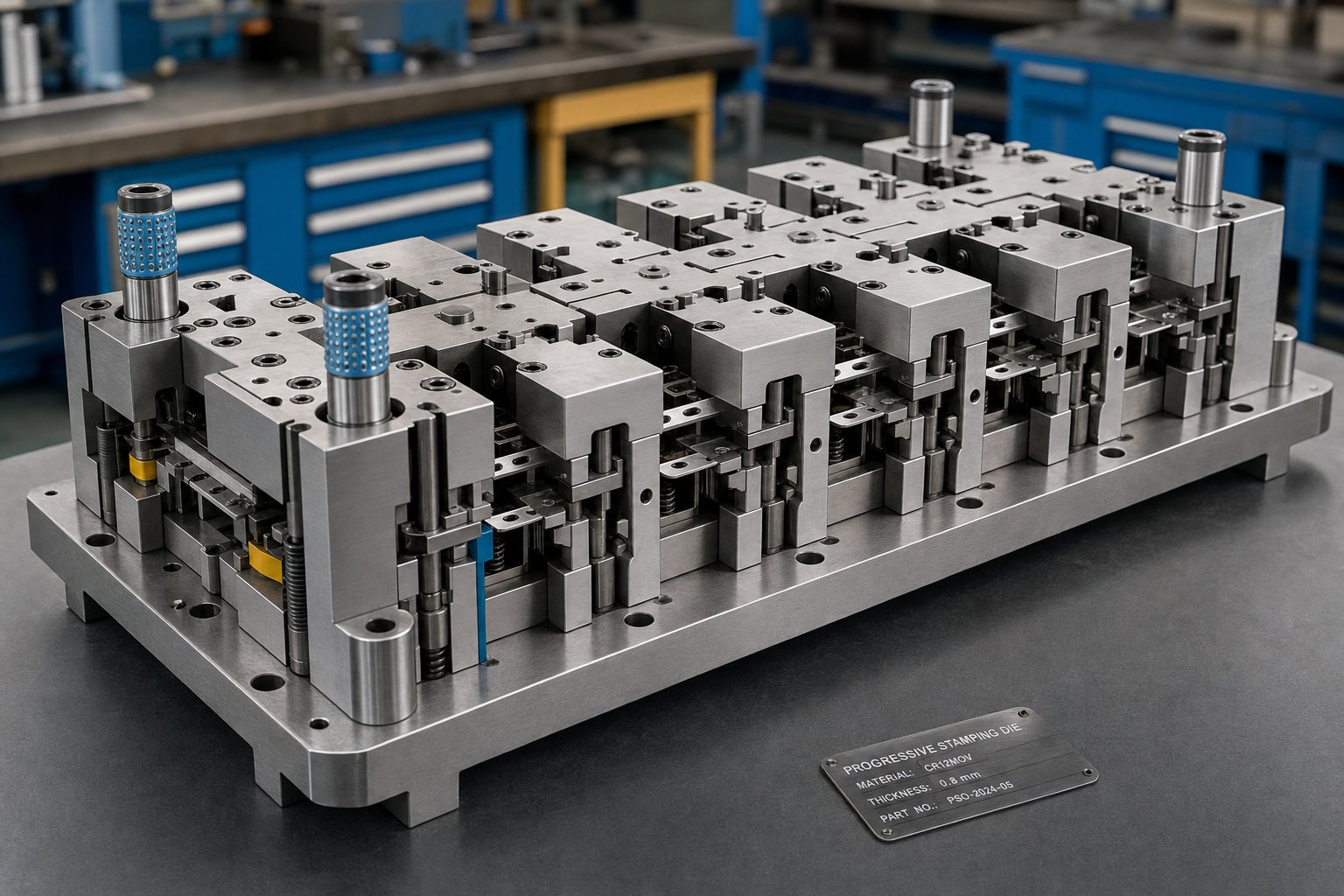
Progressive dies are the most maintenance-intensive type due to their multi-station complexity. A single progressive tool may contain dozens of cutting, forming, and idler stations, each wearing at different rates depending on the operation performed. Progressive die maintenance procedures require station-by-station inspection records, individual sharpening histories for each cutting section, and careful tracking of strip feed pitch accuracy across all stations. When one station is serviced, adjacent stations must be checked for alignment continuity. Missing this step is how a simple regrind at station 4 creates a dimensional issue at station 7.
Compound dies perform multiple operations in a single stroke, which means all cutting and forming elements engage simultaneously. Their simpler structure demands less frequent maintenance than progressive tooling, but the interactions between cutting and forming in a single plane require that clearances be checked holistically - adjusting one element affects the load on all others.
Transfer dies add mechanical transfer mechanisms to the maintenance equation. Beyond the die sections themselves, you're tracking gripper finger condition, transfer timing, and the alignment between independent stations. Each station can be serviced independently, which simplifies reconditioning scheduling, but the transfer system itself introduces wear points that progressive and compound dies don't have.
Moving from Paper Logs to Digital Tracking
Most shops don't leap from paper cards to full die management software overnight - and they shouldn't. A system only works if the people filling it out actually use it. The progression below gives you a realistic path from basic documentation to integrated tracking without overwhelming your team or your budget.
- Standardize your paper system first. Before going digital, make sure every die has a consistent record card with the essential fields listed above. If your paper system is inconsistent, digitizing it just creates organized chaos. Define what "complete" looks like for a service entry and hold to it.
- Move to a shared spreadsheet. A well-structured spreadsheet with stroke-count columns, service dates, and conditional formatting for overdue triggers gives you trend visibility that paper cards never will. This is often enough for shops running fewer than 50 active dies.
- Adopt dedicated die maintenance software. When your die inventory, service frequency, or team size outgrows spreadsheets, purpose-built systems add automated alerts, stroke-count-based triggers tied directly to press PLCs, location tracking, and historical analytics. The key differentiator from general CMMS platforms is die-specific functionality: tracking sharpening histories, cumulative stock removal, reconditioning cycles, and tooling genealogy.
- Integrate with production data. The final stage connects your maintenance records to press stroke counters, quality system reject data, and production scheduling. This eliminates manual data entry for stroke counts, flags dies automatically when service thresholds are reached, and prevents scheduling a job on a die that's overdue for service.
The transition doesn't require replacing everything at once. Each step builds on the discipline established in the previous one.
Die Storage and Corrosion Prevention
Tracking doesn't stop when the die leaves the press. How a tool is stored between production runs directly affects its condition at the next setup - and poor storage creates maintenance problems that no amount of in-press inspection will catch in time.
- Humidity control: Bare tool steel corrodes quickly in uncontrolled environments. Store dies in climate-controlled areas or use vapor corrosion inhibitor (VCI) wraps and desiccant packs in sealed enclosures. Even light surface rust changes clearances and damages part surfaces on the first hit of the next run.
- Corrosion prevention coatings: Apply a thin film of rust preventive oil to all exposed steel surfaces before storage. Choose a product that lifts off easily during pre-run cleaning without requiring aggressive solvents that could damage coatings or seals.
- Proper support to prevent deflection: Large dies stored on their sides or supported only at the edges can sag over time, introducing permanent bow in the die shoe. Store dies flat on level surfaces with support distributed across the full footprint. Never stack dies directly on top of each other.
- Protection from physical damage: Cover all exposed cutting edges, form steels, and precision surfaces. A bump from a forklift tine or a dropped wrench on an unprotected die section creates the kind of damage that shows up as a mystery defect three months later when the die goes back into production.
- Storage location tracking: Record where each die is stored and update the record when it moves. A die that can't be found costs the same as a die that doesn't exist - at least until someone locates it.
Good die storage and corrosion prevention is maintenance that happens between runs. Neglect it, and you'll spend the first hours of your next setup undoing damage that should never have occurred.
Structured tracking tells you what happened in the past and what's due next. But the most forward-looking maintenance programs don't just record history - they use real-time data to predict what's coming before a checklist or stroke counter says it's time.
Predictive Maintenance and Modern Monitoring Approaches
Stroke counters and calendar dates give you a schedule. They don't tell you what's actually happening inside the die right now. A die running soft aluminum at moderate speed may reach its trigger threshold with plenty of edge life remaining, while another die punching high-strength steel under heavy tonnage could be approaching failure well before the counter says it's time. That gap between scheduled service and actual condition is where predictive die maintenance sensors change the equation.
Sensor-Based Wear Monitoring for Stamping Dies
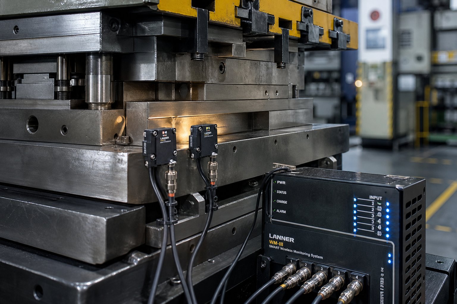
Modern condition-based stamping die monitoring relies on sensors embedded in or near the tooling to capture real-time process signatures. The most relevant sensor types for stamping applications include:
- Force and strain sensors: Mounted on the press frame or integrated into die shoes, these capture the tonnage profile of every stroke. A healthy cutting operation produces a consistent force signature. As edges dull or clearances shift, the peak force rises and the curve shape changes - often detectably before part quality degrades.
- Vibration sensors: Triaxial accelerometers detect abnormal vibration patterns that indicate misalignment, loose components, or bearing degradation in guide assemblies. Changes in vibration frequency and amplitude map to specific mechanical conditions.
- Acoustic emission sensors: These capture high-frequency stress waves generated by crack propagation, micro-fractures, or sudden material deformation events. They're particularly effective at detecting early-stage structural issues in die components that visual inspection would miss entirely.
- Temperature sensors: Elevated temperatures at forming stations or bearing surfaces indicate friction increases from inadequate lubrication or coating wear-through - conditions that accelerate tool degradation exponentially if uncorrected.
The real power isn't in any single sensor type. It's in the pattern recognition applied to continuous data streams. Machine learning algorithms trained on a die's normal operating signature can flag deviations - a gradual force increase of 3-5% over several thousand strokes, for example - and alert the tooling maintenance team while the die is still producing good parts. That window between detectable degradation and actual failure is your intervention opportunity.
McKinsey research documents that predictive approaches typically reduce machine downtime by 30 to 50 percent and increase machine life by 20 to 40 percent. Those gains don't come from harder PM compliance - they come from acting on condition data instead of calendar assumptions.
Condition-Based Triggers vs. Calendar-Based Schedules
Condition-based maintenance triggers intervention by measured asset condition, regardless of elapsed time. The calendar becomes a backstop, not the decision-maker.
The foundational reliability research behind this shift has been clear since 1978: only about 18 percent of equipment failures follow an age-related pattern that calendar-based intervals can predictably address. The remaining failure modes are either random or follow degradation curves that bear little relationship to time or stroke count alone. For stamping dies, this means a purely schedule-driven program will over-service some tools while missing developing faults on others between PM windows.
The practical shift doesn't require replacing your existing program overnight. It layers condition data on top of what you already have:
- Start with force monitoring on your highest-value dies. Even a single load cell per press gives you a tonnage trend that reveals progressive wear before it reaches the part.
- Set threshold alerts rather than fixed intervals. When punch force exceeds a defined percentage above baseline, trigger an inspection - regardless of stroke count.
- Correlate sensor alerts with maintenance outcomes. After several alert-driven interventions, you'll have data showing what condition level actually produces defects versus what merely indicates normal early wear. Use that to refine your alert thresholds.
Total productive maintenance principles reinforce this shift at the organizational level. TPM's autonomous maintenance pillar places frontline press operators as the first detection layer - they clean, inspect, and note abnormalities during every shift. When operators are trained to recognize changes in press sound, vibration feel, or part appearance, they become human sensors supplementing the electronic ones. TPM implementation data shows plants reaching 80-85% OEE within 18-24 months by combining operator ownership with planned technical maintenance - a 15-20 point gain over reactive-only programs.
The maintenance team's role in this model shifts from performing every task to documenting standards, analyzing trends, and handling the technical interventions that require specialized skill. Operators own the daily condition awareness. Technicians own the diagnostic response. Together, they close the loop between detection and action far faster than either group could alone.
Technology and culture both matter here - but neither sustains itself without organizational structure. The sensors need someone reading the alerts. The operators need training and clear escalation paths. The data needs to feed decisions, not just dashboards. Building that structure is where maintenance programs either become self-sustaining or quietly revert to firefighting.
Building a Maintenance Program and Designing for Maintainability
Sensors, checklists, and tracking systems are tools. They don't sustain themselves. Behind every effective tool and die maintenance program is an organizational structure - people with defined roles, documented procedures they actually follow, and a culture where preserving die condition is treated as production work, not an afterthought squeezed between runs. If your program depends on one experienced technician who carries everything in their head, you don't have a program. You have a single point of failure.
Building Your Maintenance Team and Documentation
A functional maintenance team doesn't need to be large, but it does need clear accountability. At minimum, you need three layers working in coordination:
- Press operators (autonomous maintenance): Responsible for daily visual checks, debris removal, lubrication verification, and escalating abnormalities. They're your first detection layer - the people who notice the sound change or the burr that wasn't there last hour.
- Die maintenance technicians: Own the scheduled service work - sharpening, component replacement, clearance verification, and diagnostic troubleshooting. They execute the checklists, record the data, and make repair-versus-replace decisions based on measured conditions.
- Tooling manager or maintenance planner: Sets priorities using the decision-tree approach, manages scheduling against production calendars, analyzes trend data, and owns the continuous improvement cycle. This role bridges the gap between shop floor execution and management-level resource decisions.
Training requirements differ across these roles but share a common foundation: everyone touching the die needs to understand what normal looks like for that specific tool. Phoenix Group's die shop management framework emphasizes that standardized work documentation - step-by-step procedures with visual references - is critical both for training consistency and for quality of repair. When every technician follows the same inspection sequence and records data in the same format, you eliminate the variability that makes maintenance outcomes unpredictable.
Documentation standards should cover three areas: procedure cards for each die (what to do, in what order, at what interval), work order records (what was actually done, what was found, what triggered the service), and escalation criteria (at what point does a finding require engineering review rather than standard corrective action). Without this structure, tool and die repair decisions become inconsistent - one technician sharpens, another replaces, and nobody tracks which approach actually extended die life.
Creating a maintenance culture goes beyond assigning roles. It means leadership treats PM compliance as a production KPI rather than a flexible suggestion. When scheduled maintenance gets bumped repeatedly because production "needs the press," you're signaling that prevention doesn't matter - and the team responds accordingly by reverting to reactive behavior.
How Die Design Decisions Affect Maintainability
Here's a reality that most maintenance teams learn the hard way: some dies are inherently easy to maintain, and some fight you every time they come to the bench. The difference isn't random. It's designed in - or neglected - during the die engineering phase. Industry analysis of die lifecycle costs confirms that design decisions made before manufacturing begins determine 70% of the total cost trajectory, including downstream maintenance burden.
Die design for maintainability means the toolmaker anticipated that wear components would need replacement, that clearances would need verification, and that the die would spend time on the bench repeatedly over its production life. When these considerations are missing, simple tasks become multi-hour disassembly projects.
Tooling managers should request - and evaluate suppliers on - these design-for-maintenance features:
- Accessible wear components: Punches, die buttons, and inserts that can be removed from the top without flipping the die or disassembling unrelated sections. Every unnecessary step during component replacement extends press downtime.
- Standardized punch and die dimensions: Using common body diameters and retention methods across stations means fewer unique spare parts and faster replacement. Proprietary or non-standard sizing locks you into a single source for consumables.
- Modular die construction: Sections that can be removed independently for service without disturbing adjacent stations. This is especially critical in progressive dies where one station's wear shouldn't require tearing down the entire tool.
- Keyed and doweled assemblies: Components that locate positively during reassembly, eliminating the need to re-indicate position after every replacement. If your technician needs a dial indicator and 45 minutes to reset alignment after swapping a punch, the design failed the maintenance team.
- Clearly marked datum surfaces: Reference points for measurement and alignment that are visible, accessible, and protected from wear. These make clearance verification fast and repeatable.
- Integrated slug relief and lubrication paths: Scrap ejection channels and oil delivery points that remain functional without modification as the die wears and is reground over its life.
When these features are present, routine service takes hours instead of days. When they're absent, even well-trained technicians spend most of their time wrestling with access rather than performing the actual maintenance work.
This is where your relationship with the die manufacturer becomes a long-term maintenance variable. A supplier that engineers maintainability into the die from the start reduces your total cost of ownership across hundreds of thousands of strokes - not just the first production run. YICHEN, for example, pairs custom stamping die manufacturing with engineering attention to durability and maintainability, designing dies where wear components are accessible, replacement parts are standardized, and modular construction supports faster teardown and reconditioning cycles. That upfront engineering investment translates directly into shorter service windows and longer intervals between major tool and die repair events over the die's full production life.
The principle holds regardless of supplier: when you evaluate die quotes, ask how the design accommodates future maintenance. A die that costs 10% more upfront but cuts your service time in half across a five-year production life isn't expensive - it's economical. The cheapest die to maintain is the one that was designed to be maintained.
Next Steps to Extend Die Life and Reduce Downtime
Programs don't improve by adding complexity. They improve by doing the right things in the right order. If you've read this far, you have the frameworks - checklists, diagnostic tables, material guidelines, tracking fields, and monitoring concepts. The question now is where to start, especially if your current approach still leans reactive.
Priority Actions for Immediate Impact
Rank your next moves by how quickly they reduce die downtime in stamping operations. The sequence below reflects the highest-return actions first, each building the foundation for the next:
- Standardize your checklists with measurable criteria. Move beyond "inspect die" and define what you're measuring, what tolerance is acceptable, and what action triggers at each interval. A checklist with pass/fail thresholds catches problems that vague instructions miss entirely.
- Track every service event with consistent data fields. Die ID, stroke count at service, what was done, what was measured, what's due next. Even a shared spreadsheet with these fields gives you the trend visibility that memory-based systems never will.
- Set stroke-count-based triggers for your highest-volume dies. Calendar intervals keep tasks from slipping, but stroke-count triggers match service to actual workload. Start with your top five dies by annual hit count and refine thresholds using your own wear data.
- Implement root cause documentation. When a failure occurs, record what you found, what caused it, and what prevention action you took. Within a few months, patterns emerge that let you eliminate recurring failures rather than repeating the same repairs.
- Layer in condition monitoring where it pays back fastest. Force monitoring on a single high-value progressive die gives you real data on how condition-based triggers compare to your schedule-based intervals - without overhauling your entire program at once.
Each step is independently valuable. You don't need step five working before step one delivers results. Start where you are, build consistency, and expand from there.
Pairing Maintenance Excellence with Die Quality
The best die maintenance program in the world can't compensate for a die that was poorly designed or built from inadequate materials. Conversely, even a well-engineered die degrades without structured upkeep. Die longevity lives at the intersection of these two forces - execution on the maintenance side and quality on the tooling side.
Die maintenance best practices extend die life significantly, but they work within the constraints of the tool itself. A die designed with accessible wear components, standardized replacement parts, and modular construction makes every checklist item faster and every service window shorter. One that fights you on disassembly or uses proprietary sizing for consumables erodes your program's efficiency from the inside.
Teams looking to reduce their maintenance burden from the source - not just manage it better after the fact - benefit from working with die manufacturers who engineer maintainability into the tool from day one. YICHEN's custom stamping dies are built with this principle in mind, pairing durable construction with design choices that support faster service cycles and longer production life between major reconditioning events.
Whether you're tightening your checklists, implementing tracking, or evaluating your next die purchase, the goal remains the same: stop chasing failures and build a system that prevents them. The tools are here. The sequence is clear. What matters now is consistent execution.
Stamping Die Maintenance FAQs
1. How often should stamping dies be maintained?
Stamping die maintenance frequency depends on both time-based intervals and stroke-count triggers. Daily tasks include visual inspection and slug removal. Weekly service covers clearance measurement and guide pin checks. Monthly work addresses sharpening and surface evaluation. However, stroke-count triggers are more accurate than calendar dates alone. Typical sharpening reviews occur every 100,000-300,000 strokes, with shorter intervals for high-strength steel or stainless steel workpieces and longer intervals for soft materials like aluminum or copper. The most effective programs layer stroke-count thresholds on top of calendar schedules, using actual wear data from each specific die to refine timing over successive service cycles.
2. What is the difference between die repair and die maintenance?
Die repair restores a broken or failed tool to working condition after an unplanned event, such as replacing a chipped punch or fixing a cracked die section. Die maintenance preserves a functioning tool in its current state through scheduled upkeep, including sharpening, cleaning, component replacement, and alignment verification performed before failure occurs. The cost difference is significant: reactive repair typically runs four times more expensive than planned maintenance when accounting for setup teardown, press idle time, quality re-verification, partial-run scrap, and lost production margin. Organizations that track both activities separately gain visibility into how much budget goes toward emergency fixes versus prevention.
3. What causes burrs on stamped parts and how do you fix them?
Burrs on stamped parts typically indicate one of three die conditions: dull cutting edges, incorrect punch-to-die clearance, or tool misalignment. The corrective approach starts with measuring clearance at multiple points around the cutting profile to determine whether the issue is uniform dulling or localized misalignment. If edges are worn, resharpening restores geometry. If clearance has shifted due to a loosened dowel or worn bushing, the root cause must be addressed before sharpening will provide lasting improvement. Prevention involves setting stroke-count-based sharpening triggers, monitoring clearance weekly, and using full-guide die construction to maintain alignment throughout production runs.
4. How do die coatings like TiN and DLC affect maintenance procedures?
Die coatings require modified maintenance approaches because abrasive cleaning methods damage the coating layer and expose the substrate to accelerated wear. TiN and TiCN coatings should never be cleaned with abrasive tools; instead, use chemical stripping methods for material buildup removal. DLC coatings have a lower temperature ceiling (around 350 degrees C) and require compatible lubricants, as some extreme-pressure additives chemically attack the carbon film. Monthly inspection should check for coating wear-through at high-contact points. Once a coating is breached, the exposed area wears rapidly, so early detection through color change monitoring is critical to timing recoating before substrate damage occurs.
5. How can die design reduce long-term maintenance costs?
Die design decisions made before manufacturing determine roughly 70% of the total lifecycle cost, including maintenance burden. Key design-for-maintainability features include accessible wear components that can be removed from the top without full disassembly, standardized punch and die dimensions that reduce spare part inventory, modular construction allowing independent station service, and keyed assemblies that eliminate re-indication after component replacement. Manufacturers like YICHEN engineer these maintainability principles into custom stamping dies from the design phase, ensuring wear components are accessible and replacement parts are standardized. A die that costs slightly more upfront but cuts service time significantly across its production life delivers lower total cost of ownership.


