


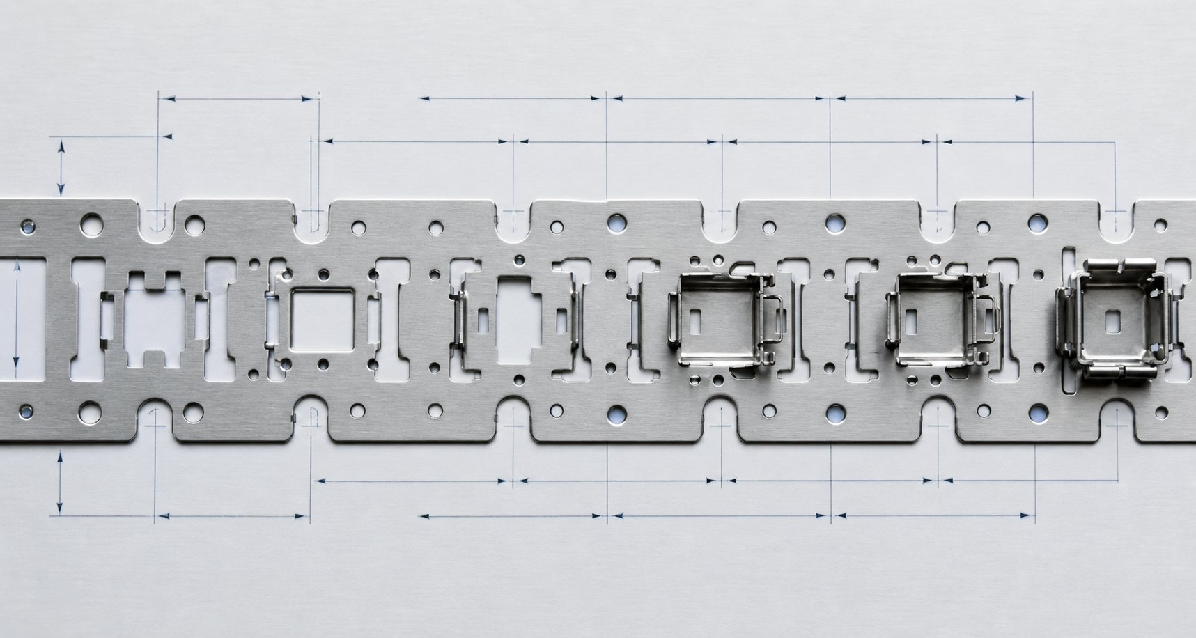
Defining Bypass Notches and Their Role in Stamping Die Engineering
When you look at a strip layout for a progressive die, you'll notice small cutouts along the carrier edges or between stations that seem almost incidental. They're not. These features, bypass notches, represent one of the most deliberately engineered aspects of sheet metal stamping dies, yet their scientific rationale is rarely documented in a way that satisfies engineering scrutiny.
What Are Bypass Notches in Progressive Stamping Dies
Bypass notches are controlled relief features deliberately cut into the carrier strip of a progressive stamping die to manage material flow, redistribute shear stress, and reduce snap-through forces during forming operations. They exist as both negative notches (material removed) and positive notches (material added or left standing) to selectively modify strip rigidity at critical locations.
So what is metal stamping at its core? It's the transformation of flat sheet material into finished geometry through a sequence of cutting, bending, and forming operations. In a progressive die, the strip advances through multiple stations while still attached to a carrier web. Each station applies forces that interact with adjacent stations through the strip itself. Bypass notches interrupt this force transmission path in a controlled manner, isolating deformation zones so each station can do its work without corrupting neighboring features.
The stamping definition most engineers learn covers the basic mechanics of punching and forming. But understanding what are dies in practice means recognizing that every feature in a progressive die strip layout serves a mechanical purpose. Bypass notches are no exception. They function as engineered stress boundaries, controlling where and how the carrier strip deforms during each press stroke.
Why Engineering Rationale Matters Beyond Shop-Floor Tradition
Here's the problem. Many negative and positive bypass notches in sheet metal stamping dies were developed through decades of trial-and-error in tool rooms. An experienced die maker adds a notch because "it worked last time" or "that's how we've always done it." The result? Specifications that can't be defended in a design review, can't be scaled to new materials or geometries, and can't be optimized without expensive tryout cycles.
If you're a die designer or process engineer, you need more than inherited practice. You need the engineering rationale that explains why a specific notch depth, width, and placement produces the desired stress relief. You need to understand the mechanics well enough to predict what happens when material properties change, when strip width narrows, or when forming severity increases at a particular station.
This article bridges that gap. Rather than simply stating that bypass notches are used in the stamping process, it explains the underlying science: stress distribution theory, material anisotropy, controlled relief mechanics, and their interaction with carrier strip design. The goal is to give you the vocabulary and the physics to specify bypass notches with confidence, backed by first principles rather than shop-floor folklore alone.
The mechanics start with understanding exactly how forces propagate through a carrier strip during forming, and what happens at the material level when you introduce a deliberate discontinuity into that load path.
Fundamental Mechanics Behind Bypass Notch Function
Imagine a continuous strip of sheet metal advancing through a progressive die. At every station, punches and forming tools apply forces to specific zones of that strip. The carrier web connecting those zones isn't passive. It transmits forces laterally, meaning what happens at station four can influence the material state at station five before the press even contacts it. This force coupling is where bypass notches earn their engineering value.
The metal stamping process in a progressive die subjects the carrier strip to a complex, competing set of loads during every press stroke. Drawing operations pull material inward. Punching stamping operations generate sudden shear release. Bending operations shift the neutral axis and induce localized strain. Without intervention, the carrier strip acts as a rigid bridge that transmits all of these forces simultaneously across stations, creating unpredictable interactions that degrade dimensional accuracy.
Bypass notches solve this by performing three distinct mechanical functions:
- Controlling material flow - By creating controlled relief points in the carrier, bypass notches allow sheet metal to deform locally without excessive constraint from adjacent stations. Material can draw inward or stretch outward at a forming station without dragging the neighboring blank geometry along with it.
- Redistributing shear stress - During cutting and piercing operations, shear stress concentrates at the tool-to-material interface. Bypass notches redirect residual stress away from critical forming zones, preventing localized yielding or micro-cracking that would otherwise propagate into finished part features.
- Reducing snap-through forces - When a punch breaks through the material during blanking or piercing, the sudden release of stored elastic energy creates a snap-through event. This shock transmits through the strip and can lift it off the die surface, causing mis-feeds and pilot misalignment at downstream stations.
How Bypass Notches Control Material Flow During Forming
In any sheet metal stamping operation involving drawing or stretching, material must flow from surrounding areas into the forming zone. If the carrier strip is too rigid near that station, it resists this flow. The result is excessive thinning in the part wall, wrinkling at the flange, or outright splitting. A bypass notch positioned upstream or downstream of the draw station reduces the carrier's cross-sectional resistance, letting material move freely into the die cavity without fighting the strip's longitudinal stiffness.
This is the same principle behind stretch web carriers described in progressive die design literature. As carrier strip design guidance notes, a solid carrier allows no vertical movement of parts, and the entire strip must remain flat throughout the stroke. Bypass notches introduce selective compliance, giving each station the freedom to deform independently while the strip still feeds reliably.
Stress Redistribution and Snap-Through Force Reduction
When a punch shears through material, the stored elastic energy in the strip releases almost instantaneously. This snap-through generates a force spike that travels through the carrier in both directions. In a strip without relief features, that spike reaches adjacent stations as a transient shock load. Over thousands of cycles, this repeated impulse fatigues the carrier, distorts pilot hole geometry, and accelerates die wear at neighboring stations.
Bypass notches act as mechanical low-pass filters. The reduced cross-section at the notch absorbs and attenuates the force pulse before it reaches the next station. The notch root deforms elastically under the transient load, converting kinetic energy into localized strain rather than transmitting it down the strip. Modern stamping technology leverages this principle to maintain tighter tolerances at higher press speeds, where snap-through forces become more severe due to increased acceleration and deceleration of the ram.
Preventing Strip Lifting and Mis-Feed Conditions
Strip lifting is one of the most common production disruptions in progressive die operations. When snap-through forces or unbalanced forming loads push the strip upward off the die surface, the pilots cannot re-engage cleanly on the next feed cycle. The strip advances in a misaligned state, causing oversized holes, shifted bend lines, and in severe cases, pilot pin shearing.
Among proven metal stamping techniques for preventing this, bypass notches reduce the strip's ability to transmit vertical force components between stations. A notch between a heavy blanking station and a precision forming station decouples their dynamic behavior. The blanking station's snap-through stays local. The forming station's strip contact remains stable. Feed accuracy stays within tolerance.
Without these relief features, the carrier strip's rigidity becomes a liability rather than an asset. It transmits every force event across the entire die, creating dimensional errors that compound through each station and progressive material fatigue that shortens carrier life. The geometry of those notches, their depth, width, angle, and root radius, determines exactly how much decoupling they provide. That geometry depends directly on stress distribution theory and material properties, which govern how the strip responds to deliberate discontinuities in its cross-section.

Stress Distribution Theory and Notch Geometry Parameters
Every bypass notch introduces a geometric discontinuity into the carrier strip. That discontinuity changes how stress flows through the material, and the specific geometry of the notch determines whether it provides functional decoupling or simply weakens the strip without delivering meaningful relief. The difference comes down to stress concentration theory and how it interacts with the strip's load-bearing cross-section during progressive die operations.
Stress Concentration Theory Applied to Notch Geometry
A stress concentration occurs wherever there is an abrupt change in geometry that forces the internal load path to divert around a discontinuity. You can visualize stress as flowing through a part like streamlines in a fluid. Where those lines bunch together, around a hole, a notch root, or a sharp corner, the local stress rises significantly above the nominal value in the surrounding material. The ratio of peak local stress to nominal stress is the stress concentration factor, Kt.
In stamping die design, a bypass notch is a deliberate stress raiser. That sounds counterintuitive. Why would you intentionally create a location where stress is amplified? Because the notch sacrifices a controlled zone of carrier material to protect the part geometry. By concentrating strain energy at the notch root, you redirect deformation away from forming features and into a region where it does no harm to the finished part. The notch absorbs the competing forces between stations so that critical forming zones remain undisturbed.
The relationship between notch root radius and Kt is well established in engineering mechanics. A sharper radius at the notch root produces a higher stress concentration factor, meaning peak stress at that location increases dramatically relative to the surrounding strip. A broader, more generous radius distributes the load over a wider area, reducing peak stress but also reducing the notch's effectiveness as a decoupling feature. Research on notch effects confirms that as Kt increases, the local stress field becomes more severe and more localized, while lower Kt values spread the stress over a larger zone.
For a rectangular bar with opposite edge notches, if the bar is 12 mm wide with a notch radius of 2 mm, the stress concentration factor reaches approximately 3.05. This means peak stress at the notch root is over three times higher than the nominal stress in the remaining cross-section. In progressive die carrier strips, the same principle applies. A notch with a tight root radius concentrates stress sharply, creating an aggressive decoupling boundary. A notch with a large root radius produces a more gradual transition, suitable for applications where you need partial relief without risking fatigue cracking at the notch root over thousands of press cycles.
This is the core tradeoff in metal stamping die design: sharper notches decouple more effectively but create higher fatigue risk; gentler notches last longer but may not provide sufficient isolation between stations. The die process requires balancing these competing demands based on production volume, material properties, and the severity of forming operations at adjacent stations.
Neutral Axis Shift and Its Influence on Notch Placement
During bending operations in a progressive die, the material's neutral axis, the plane where stress transitions from tension on the outer surface to compression on the inner surface, does not remain at the geometric center of the sheet thickness. It shifts toward the inside of the bend. The degree of shift depends on the ratio of bend radius to material thickness (R/t ratio) and the material's work hardening characteristics.
Why does this matter for bypass notch placement? Because the neutral axis shift determines where the strip experiences maximum tensile strain during forming. If a bypass notch is positioned where the carrier strip undergoes bending as it transitions between stations, the notch root becomes the location of maximum strain concentration superimposed on the already-elevated bending strain. Placing the notch at the wrong location along the strip's bending profile can turn a functional relief feature into a crack initiation site.
The minimum bend radius relationship provides guidance here. For a given material thickness t, there's a minimum inside bend radius below which the outer fibers exceed their elongation limit and crack. When the R/t ratio is small (tight bends), the neutral axis shifts significantly inward, sometimes to 30-40% of the thickness from the inner surface rather than the nominal 50%. A bypass notch placed in a region that experiences this tight-radius bending must account for the elevated outer-fiber strain. The notch root radius must be generous enough that its own stress concentration does not compound the bending strain to the point of fracture.
In practical stamping design, this means bypass notches are best positioned in flat regions of the carrier strip, away from any natural bending that occurs as the strip lifts over lifters or flexes between die stations. When a notch must exist near a bend transition, its depth and root radius require careful specification to prevent the combined stress state from exceeding the material's fatigue endurance.
The critical parameter is notch depth relative to material thickness. A notch that removes 30-50% of the strip's cross-section at the carrier edge creates sufficient reduction in bending stiffness to decouple adjacent stations. A notch that removes only 10-15% of the cross-section may be too shallow to meaningfully interrupt force transmission, creating a weakened zone without functional benefit. Conversely, a notch exceeding 60% of strip width compromises feeding rigidity and can cause the carrier to buckle under the feed mechanism's pushing force.
The following table summarizes the key geometry parameters for a metal stamping die bypass notch and the engineering rationale behind each specification:
| Geometry Parameter | Typical Range | Engineering Rationale |
|---|---|---|
| Notch Depth | 30-50% of carrier width | Must reduce cross-sectional stiffness enough to decouple station forces. Too shallow provides no relief; too deep compromises strip feeding integrity. |
| Notch Width (along strip direction) | 1.0t to 3.0t (t = material thickness) | Controls the length of the stress transition zone. Wider notches create a longer compliant region but consume more strip material and reduce feed pitch efficiency. |
| Notch Angle (sidewall taper) | 0° to 30° from perpendicular | Angled sidewalls reduce the abruptness of the geometric transition, lowering Kt at the notch entry points. Perpendicular walls create sharper stress gradients for aggressive decoupling. |
| Root Radius | 0.5t to 2.0t minimum | Directly controls Kt at the deepest point. Smaller radii concentrate stress more aggressively but increase fatigue risk. Larger radii spread load and extend carrier life at the cost of less localized decoupling. |
| Depth-to-Thickness Ratio | Varies by material ductility | Determines whether the notch root remains in the elastic regime during cyclic loading or undergoes plastic deformation that leads to progressive cracking. |
Each of these parameters interacts with the others. A deep notch with a generous root radius can provide the same effective Kt as a shallower notch with a tighter radius, but they produce different strain field geometries and different fatigue performance over production life. The stamping design decision depends on which combination delivers adequate station decoupling while surviving the required production volume without carrier cracking.
These geometry relationships tell you how to size a bypass notch for a given stress state. But the material itself determines how that notch actually behaves under load. Ductile materials redistribute stress through local yielding at the notch root, effectively blunting the concentration over time. Brittle or high-strength materials cannot redistribute as readily, making the as-designed Kt value a much more accurate predictor of real-world performance. The material's tensile properties, work hardening rate, and elongation capacity all influence how forgiving or unforgiving a given notch geometry will be in service.
Material Properties That Drive Bypass Notch Dimensions
A notch geometry that performs flawlessly in mild steel can cause catastrophic carrier cracking in stainless steel within a few thousand hits. The same depth and root radius that provides clean decoupling in one material may produce either insufficient relief or premature fatigue failure in another. Material properties are not secondary considerations in bypass notch specification. They are the primary drivers.
Four mechanical properties dominate bypass notch behavior: tensile strength, yield strength, elongation percentage, and the work hardening exponent (n-value). Together, these determine how the carrier strip responds to the repeated cyclic loading at the notch root during progressive die operation. Research into robust stamping processes confirms that material characterization is essential not just for forming the part geometry, but for every link in the production chain, including carrier strip reliability.
Mild Steel and Carbon Steel Notch Design Principles
Carbon steel stamping represents the most forgiving scenario for bypass notch design. Mild steels like SPCC, SAE 1008, and SAE 1010 typically offer elongation values of 28-42% and moderate tensile strengths in the 270-400 MPa range. That high elongation translates directly into tolerance for deeper notches. The material at the notch root can undergo localized plastic deformation without crack initiation because it has substantial ductility reserve remaining after the notch geometry concentrates strain.
When you're working with cold rolled steel stamping in the mild steel category, the relatively low yield-to-tensile ratio (typically 0.55-0.70) means the material work hardens progressively as it deforms. This is actually beneficial at the notch root. As the carrier strip flexes during each press stroke, the notch root strain-hardens slightly, increasing its local resistance to further deformation. The hardening stabilizes within the first few hundred cycles, and the notch root reaches a steady state where cyclic strain remains elastic. This self-stabilizing behavior is why mild stamped steel carriers can tolerate notch depths of 40-50% of carrier width without fatigue cracking, even at production volumes exceeding a million hits.
The work hardening index for mild steel typically falls between n = 0.18 and n = 0.24. Higher n-values promote more uniform strain distribution around the notch, meaning the stress concentration effect is blunted as the material yields and spreads the deformation zone outward. A higher n-value effectively reduces the realized stress concentration below the theoretical Kt, giving designers more latitude in notch geometry specification.
Aluminum and Copper Alloy Considerations
The aluminum stamping process introduces a different set of constraints. Aluminum alloys used in progressive die work, commonly 5052-H32, 6061-T4, and 3003-H14, have lower shear strength and lower elongation compared to mild steel. They also exhibit a tendency toward galling, where material adheres to the punch or die surface during shearing. This galling produces rough, irregular notch surfaces with micro-tears that act as additional stress raisers beyond the designed notch geometry.
Aluminum's lower work hardening capacity (n-values typically 0.08-0.16 depending on temper) means the notch root cannot redistribute stress as effectively through local yielding. The strain stays concentrated rather than spreading outward. Combine this with aluminum's lower fatigue endurance limit, and you get a material that demands more conservative notch designs: shallower depths, larger root radii, and smoother surface finishes at the notch.
Copper alloys such as C26000 (cartridge brass) offer better elongation than aluminum but introduce their own challenge. Brass work hardens rapidly during the initial stages of deformation, then the hardening rate drops off. This means the first few forming stations in a progressive die can significantly alter the carrier strip properties near a bypass notch, changing its fatigue response partway through the strip's travel. Designers working with copper alloys need to account for the cumulative work hardening the carrier experiences before it reaches stations with aggressive forming operations.
High-Strength Steel and Stainless Steel Challenges
High-strength low-alloy (HSLA) steels and advanced high-strength steels (AHSS) present the most demanding scenario for bypass notch design. These materials, including grades like HSLA 340, DP 590, and DP 780, combine high tensile strength (500-900 MPa) with reduced elongation (12-24%). The higher strength means greater elastic energy storage in the strip during forming, which amplifies snap-through forces. The lower elongation means less tolerance for plastic strain at the notch root before crack initiation occurs.
For steel sheet stamping in the high-strength category, bypass notches must be shallower and carry significantly larger root radii. Where mild steel tolerates a notch depth of 45% of carrier width with a root radius of 1.0t, an HSLA steel of the same thickness may require limiting depth to 25-35% with a root radius of 1.5t to 2.5t. The reduced depth means less aggressive station decoupling, which sometimes forces the designer to add idle stations or use multiple shallower notches in sequence rather than a single deep notch.
Stainless steels, particularly austenitic grades like 304 and 316, compound the challenge with extremely high work hardening rates (n-values of 0.40-0.55). This sounds beneficial based on the mild steel logic, but the effect is different at high n-values combined with high tensile strength. The notch root hardens so aggressively during the first few press cycles that it becomes locally brittle. The material around the notch transforms from ductile sheet into a hardened zone with significantly reduced remaining elongation. Subsequent cyclic loading at that hardened notch root initiates fatigue cracking much sooner than the bulk material properties would suggest.
This is why stainless steel progressive die carriers require the most conservative notch geometries: generous root radii (2.0t or greater), moderate depths, and in some cases, stress-relieving features like secondary relief holes at the notch terminus to arrest crack propagation before it reaches critical carrier cross-sections.
| Material Type | Relative Notch Depth | Root Radius Guidance | Key Property Driving the Decision |
|---|---|---|---|
| Mild Steel (SPCC, SAE 1008-1010) | 40-50% of carrier width | 0.5t to 1.0t | High elongation (28-42%) provides large ductility reserve at notch root |
| HSLA Steel (340-550 MPa class) | 25-35% of carrier width | 1.5t to 2.5t | Reduced elongation (12-22%) limits plastic strain tolerance before cracking |
| Advanced High-Strength Steel (DP 590-980) | 20-30% of carrier width | 2.0t to 3.0t | High stored elastic energy combined with limited elongation; elevated snap-through forces |
| Aluminum Alloys (5052, 6061, 3003) | 30-40% of carrier width | 1.5t to 2.0t | Low shear strength and galling tendency create irregular notch surfaces; low fatigue endurance |
| Copper Alloys (C26000, C51000) | 35-45% of carrier width | 1.0t to 1.5t | Rapid initial work hardening alters carrier properties progressively through die stations |
| Austenitic Stainless Steel (304, 316) | 25-35% of carrier width | 2.0t to 3.0t | Extreme work hardening rate (n = 0.40-0.55) causes local embrittlement at notch root |
The underlying principle connecting all these material families is the same: work hardening characteristics determine how much repeated flex the carrier strip can tolerate near a notch before fatigue cracking initiates. A material with high elongation and moderate work hardening (mild steel) self-stabilizes at the notch root, reaching a safe steady-state strain cycle. A material with low elongation or extreme hardening (AHSS, stainless) exhausts its ductility at the notch root within relatively few cycles, demanding more conservative geometry to keep cyclic strains within the elastic regime.
This material-dependent behavior also explains why a single set of "standard" bypass notch dimensions cannot exist. Every notch specification must be matched to the specific alloy, temper, and thickness being processed. Copying a notch geometry from a mild steel die into an HSLA steel application is one of the most common root causes of premature carrier failure in progressive die operations.
Material anisotropy adds yet another layer of complexity. The mechanical properties discussed here, tensile strength, elongation, work hardening, are not uniform in all directions within the sheet. Rolling direction, transverse direction, and diagonal orientations each produce different values. How that directional variation interacts with bypass notch orientation determines whether crack propagation follows a predictable, manageable path or an unexpected trajectory that threatens strip integrity.
Grain Direction and Anisotropic Material Flow
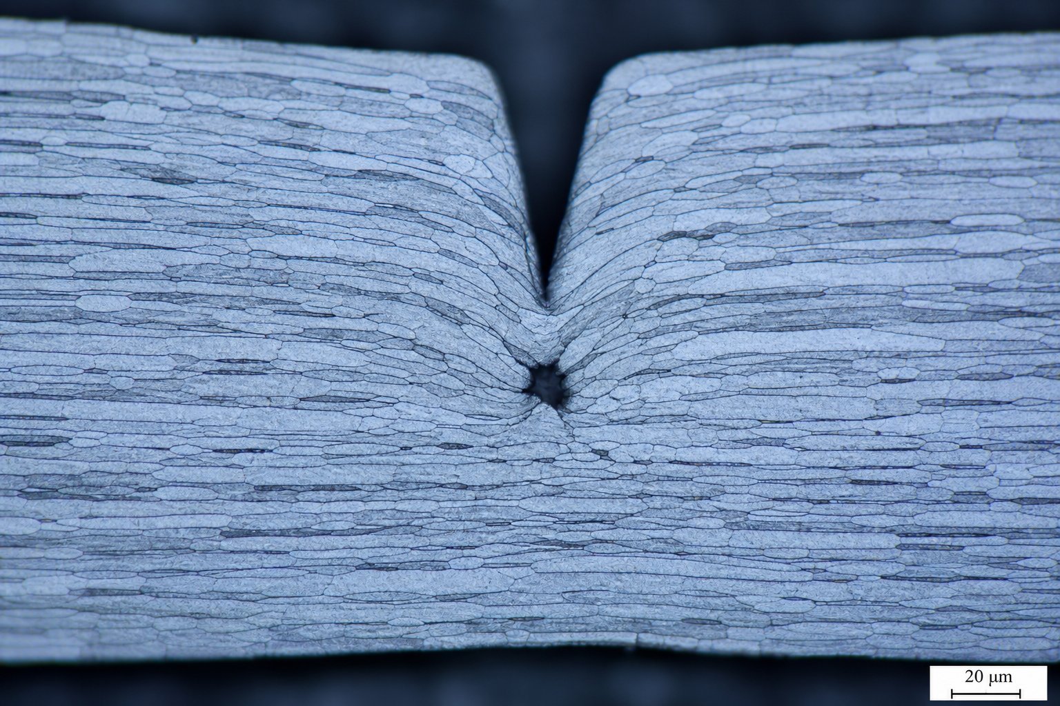
Sheet metal is not a uniform, direction-independent material. During rolling at the steel mill, the crystalline grain structure elongates in the rolling direction, creating a material that resists deformation differently depending on which direction you push, pull, or cut it. This directional dependence, called anisotropy, directly influences how a bypass notch behaves, how cracks propagate from its root, and how material flows around it during forming operations.
Anisotropic Behavior and Rolling Direction Effects
When stamping sheet metal from coil stock, the strip feeds through the progressive die with its rolling direction aligned along the feed axis. This means every bypass notch cut into the carrier edge has a fixed geometric relationship to the grain structure. That relationship is not neutral. Materials with a grain direction that affect deformation behavior are considered anisotropic, and this property varies by alloy. Cold-rolled steel exhibits pronounced grain effects, aluminum shows moderate sensitivity, and copper is largely isotropic.
The practical consequence is straightforward. Stamped sheet metal has higher tensile strength and lower elongation in the rolling direction compared to the transverse direction. The yield strength can differ by 10-20% between orientations. For a bypass notch cut perpendicular to the strip edge, the notch root stress field interacts with material that has different resistance to deformation on each side of the crack plane. One direction yields more easily; the other holds firmer. This asymmetry changes how the strain field develops around the notch under cyclic loading, and it determines whether fatigue cracks grow in a stable, predictable manner or deviate into unexpected paths.
Notch Orientation Relative to Grain Structure
Consider what happens at the microstructural level. A bypass notch oriented parallel to the grain direction, meaning its depth runs along the elongated grain boundaries, encounters less resistance to crack propagation. The grain boundaries themselves act as preferential fracture paths. In this orientation, a notch root crack can extend along the weakened intergranular planes with relatively little energy. The result is faster crack growth but also a more predictable crack trajectory, which can be advantageous if the designer accounts for it.
A notch oriented perpendicular to the grain direction must drive cracks across the grains rather than between them. This requires significantly more energy and produces greater resistance to crack growth, a desirable outcome for carrier longevity. However, the perpendicular orientation also means the notch interacts with the material's lower-elongation axis during forming, potentially causing unexpected material flow patterns during drawing operations. Material that you expect to flow freely into a forming cavity may resist movement because the notch relief is fighting the grain's preferred deformation direction.
During the metal pressing process in progressive die operations, drawing and forming stations rely on bypass notches as controlled relief points to prevent wrinkling, splitting, or excessive thinning. If the notch orientation works against the grain structure, the material may not flow as intended. Splits occur when strains cause material to thin beyond safe limits, and grain-notch misalignment concentrates those strains rather than relieving them. Engineers must consider strip orientation in the coil relative to final part geometry when specifying bypass notch placement.
Key considerations when evaluating grain direction impact on bypass notch performance:
- Coil orientation relative to feed direction - Confirm whether the rolling direction runs parallel or perpendicular to the strip feed axis, as this establishes the baseline relationship between all notches and the grain structure.
- Notch root crack propagation path - Notches parallel to grain direction propagate cracks faster along grain boundaries; notches perpendicular to grain resist crack growth but may restrict material flow during forming.
- Material-specific sensitivity - Cold-rolled steel and stainless steel show strong anisotropic effects; hot-rolled steel and copper are less sensitive. Aluminum falls between, with temper condition influencing the degree of grain elongation.
- Forming severity at adjacent stations - High-severity draws or stretches near a bypass notch require the relief to align with the preferred material flow direction, not against it, to prevent localized necking or splitting.
- Fatigue life versus decoupling tradeoff - Grain-parallel notches decouple more aggressively but fatigue sooner; grain-perpendicular notches last longer but may require greater depth to achieve equivalent stress relief.
- Grain size effects - Finer-grained materials resist crack propagation more uniformly regardless of orientation, while coarse-grained materials amplify directional differences in fracture behavior.
The takeaway for die designers is clear. You cannot specify bypass notch geometry in isolation from strip orientation. The same notch depth and root radius will perform differently depending on whether it aligns with or cuts across the grain structure. This interaction between notch geometry and material anisotropy must be evaluated alongside the strip layout decisions that determine where notches sit relative to pilot holes, carrier widths, and forming stations throughout the progressive die.
Progressive Die Strip Layout Integration and Design Tradeoffs
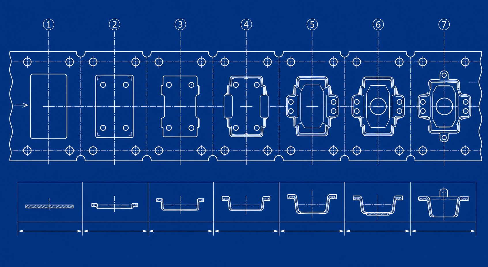
Bypass notches don't exist in a vacuum. They share the strip with pilot holes, carrier webs, idle stations, forming features, and cut-off tabs, all competing for the same limited real estate. The purpose of bypass notches in stamping dies can only be realized when their placement respects the integrated system of the strip layout. A perfectly sized notch in the wrong location relative to a pilot hole or bend line creates more problems than it solves.
Bypass Notch Placement Within Strip Layout Systems
In any progressive stamping tool and die design, the strip layout defines a sequence of operations that must be precisely coordinated. Each station applies forces that interact through the carrier strip. Bypass notches sheet metal forming applications position these relief features between stations where force decoupling is needed most, typically between a heavy blanking or piercing station and a precision forming or draw station downstream.
Placement decisions must account for several neighboring features simultaneously. Pilot holes, which provide the strip's positional reference at each station, require stable material around them. A bypass notch positioned too close to a pilot hole weakens the surrounding material, causing the hole to elongate under feeding loads and destroying registration accuracy. Industry practice maintains a minimum distance of 2-3 times material thickness between a notch boundary and the nearest pilot hole edge.
Idle stations, common in complex progressive dies, provide natural locations for bypass notches. These stations perform no forming work, so the carrier strip at that location carries no process-related loads beyond feeding force. Placing a notch within an idle station means the reduced cross-section only needs to survive feeding loads rather than combined feeding-plus-forming loads. This is also relevant in strip layout optimization, where engineers balance carrier strength against material utilization across every station.
Engineering Tradeoffs in Depth and Width Specification
The fundamental tradeoff is simple to state but difficult to optimize: a notch that is too shallow provides insufficient stress relief and fails to decouple adjacent stations, while a notch that is too deep compromises strip integrity and feeding accuracy through the die. Between these extremes lies a functional window that varies with every application.
A shallow notch, removing only 15-20% of the carrier width, barely interrupts the force transmission path. The remaining cross-section retains enough stiffness to transmit snap-through forces and forming loads between stations almost undiminished. The notch exists geometrically but delivers no mechanical benefit. You've consumed strip width for nothing.
An excessively deep notch, removing 60% or more of carrier width, dramatically reduces the strip's resistance to buckling under feed-direction compressive loads. When the feeder pushes the strip forward, the weakened section collapses or deflects laterally rather than transmitting motion to downstream stations. The result is inconsistent pitch, pilot misalignment, and potential die damage. This scenario worsens in transfer stamping applications where the strip must maintain rigidity across longer unsupported spans between die stations.
Understanding negative and positive bypass notches in sheet metal forming stamping dies clarifies the designer's options. Negative bypass notches remove material from the carrier edge, creating localized flexibility. They reduce the carrier's cross-sectional area and bending stiffness at that point, allowing adjacent stations to deform independently. Positive bypass notches work the opposite way: they add material or leave a protruding tab at the strip edge to create localized stiffening. A lance and bend pitch stop, for example, creates a downward flange that stiffens the carrier and aids feeding while simultaneously providing a solid stop reference. Each type serves a distinct mechanical purpose within the same strip layout.
Interaction With Pilot Holes and Carrier Width
Carrier width determines how much material is available for both feeding rigidity and notch relief. A narrow carrier, 3-5 mm wide, leaves almost no room for meaningful notch depth before the remaining ligament becomes too weak to feed reliably. Wider carriers, 8-12 mm or more, give designers greater flexibility to specify deeper notches while maintaining sufficient residual cross-section for stable feeding. Stage tooling arrangements in multi-station dies often require wider carriers specifically to accommodate both pilot holes and bypass notches without interference.
The sequential decision process for specifying bypass notch parameters in a new progressive die design follows a logical engineering sequence:
- Identify force-critical station boundaries - Determine which adjacent stations create the most problematic force coupling based on forming severity, snap-through magnitude, and material flow requirements.
- Establish carrier width and pilot hole locations - Define the strip's structural framework first, ensuring adequate material surrounds each pilot for positional stability under feeding loads.
- Select notch type based on mechanical need - Choose negative notches where flexibility and decoupling are required, or positive notches where localized stiffening and feed control are the priority.
- Determine notch depth from material properties - Apply the material-specific depth guidelines (covered in the preceding material properties discussion) to establish a starting depth that balances decoupling against carrier fatigue life.
- Specify root radius for target fatigue life - Match the root radius to the expected production volume and the material's work hardening behavior, using larger radii for high-volume or high-strength applications.
- Verify clearance to adjacent features - Confirm that the notch boundary maintains minimum distances from pilot holes, bend lines, and forming feature boundaries to prevent stress field overlap.
- Validate strip feeding integrity - Check that the remaining carrier cross-section at the notch location can resist buckling under the feeder's pushing force without lateral deflection or pitch variation.
This sequence ensures that bypass notches sheet metal forming purpose is fulfilled within the constraints of the complete strip layout system. Each step builds on the previous one, and skipping any step risks creating a notch that either fails to perform its decoupling function or introduces a new failure mode into the strip.
The decisions made here at the layout level translate directly into measurable outcomes on the press floor. Notch geometry affects not only station decoupling and feeding accuracy but also burr formation patterns, shear fracture direction, and punch-to-die clearance interaction, all of which determine final part quality.
Applying First Principles to Practical Notch Design Decisions
Strip layout geometry, material properties, and stress concentration theory all converge at a single point: the moment you commit a notch dimension to a die design drawing. Everything discussed so far provides the reasoning. This section translates that reasoning into decisions you can defend in a design review, troubleshoot on the press floor, and communicate clearly to your stamping tooling partners.
From Theory to Practice in Notch Sizing Decisions
The structured engineering approach works like this. First, define the problem: what forces act on the carrier strip at a given station boundary, and what material behavior limits the strip's ability to absorb those forces without dimensional distortion? Second, state the principle: a controlled relief feature modifies the local stress state by concentrating strain at a sacrificial zone, decoupling adjacent stations so each forming operation proceeds independently. Third, apply to design: size the notch depth, width, and root radius using the material-specific guidelines and stress concentration relationships covered earlier, then verify that the remaining carrier cross-section supports stable feeding.
Many shop-floor conventions encode real physics, but some have outlived their original context. Here are common rules of thumb and the science behind them:
- "Use a notch depth equal to half the carrier width." - Validated for mild steel at moderate production volumes. The 50% depth provides aggressive decoupling, and mild steel's high elongation supports it. Contradicted for HSLA and stainless steels where 50% depth exhausts ductility at the notch root within thousands of cycles.
- "Always match notch width to material thickness." - A reasonable starting point. The science confirms that a notch width of 1.0t to 1.5t creates an effective stress transition zone for most materials. Wider notches (2.0t-3.0t) are justified when the forming severity at adjacent stations is high and a longer compliant region is needed.
- "Sharp-cornered notches work fine if you're running low-carbon steel." - Partially validated. Mild steel's ductility blunts sharp notch roots through local yielding, reducing the effective Kt over the first few hundred hits. But even in mild steel, a root radius below 0.5t accelerates fatigue at volumes above 500,000 parts. The science says always specify a minimum radius.
- "If the strip is feeding OK, the notch is deep enough." - Contradicted. Feed stability confirms only that the carrier retains sufficient rigidity. It says nothing about whether the notch actually decouples station forces. A strip can feed perfectly while still transmitting snap-through loads that degrade dimensional accuracy at downstream stations.
- "Add a notch wherever you see strip lifting." - Partially validated. Strip lifting indicates force transmission between stations, and a notch can attenuate it. But the root cause may be inadequate stripper pressure or incorrect lifter timing rather than missing relief geometry. Diagnose before cutting.
Bypass Notch Influence on Burr Formation and Part Quality
Here's a connection many engineers overlook: bypass notches affect burr height on finished parts. When a cutting punch shears through the strip, the fracture pattern depends on how stress distributes through the material at the moment of breakthrough. Burr variation in progressive die operations often traces back to inconsistent stress states at the cutting zone rather than clearance alone. A bypass notch positioned near a blanking or piercing station alters the residual stress field in the material being cut. If that altered stress state changes how the punch engages the sheet, the shear-to-fracture ratio shifts, and burr height changes with it.
Specifically, bypass notches burr formation stamping interactions work like this: a notch immediately upstream of a cutting station can relieve compressive residual stress in the strip, allowing the punch to enter the material more cleanly and produce a more consistent cut band. Conversely, a poorly placed notch can introduce tensile residual stress at the cutting zone, causing the material to fracture prematurely and increasing burr height on the breakout side. The physics of metal cutting show that approximately one-third of the cut edge is shear (the burnished zone) and two-thirds is fracture in low-carbon steel at correct clearance. Anything that shifts this ratio, including residual stress from adjacent bypass notches, changes the edge quality.
Punch-to-die clearance and bypass notch stress fields must be considered together for precision die stamping results. Clearance determines the angle at which fracture cracks propagate from punch and die edges toward each other. Residual stress from a nearby bypass notch biases that crack propagation angle. If the notch-induced stress aligns with the clearance geometry, fractures meet cleanly and burr stays minimal. If they conflict, the fracture paths offset, producing a ragged edge with elevated burr. On a die stamping press running at high speed, this interaction becomes more pronounced because the dynamic forces amplify any stress field asymmetry.
The goal here is not to add complexity for its own sake. It's to give engineers the vocabulary and rationale to communicate metal stamping tooling specifications with confidence. When you specify a bypass notch depth of 35% with a 1.5t root radius positioned 3t away from the nearest cutting station, you should be able to explain why: because that geometry provides adequate station decoupling for the material grade without introducing residual stress that would alter shear fracture patterns at adjacent cutting operations. That's the difference between a specification based on science and one based on hope.
These principles hold in controlled conditions, but high-volume production introduces cumulative effects that single-hit analysis cannot predict. Repeated cycling, progressive die wear, and thermal expansion shift the stress state over time, revealing whether a bypass notch design has adequate margin or is operating at the edge of its performance envelope.
Real-World Indicators and Diagnostic Application
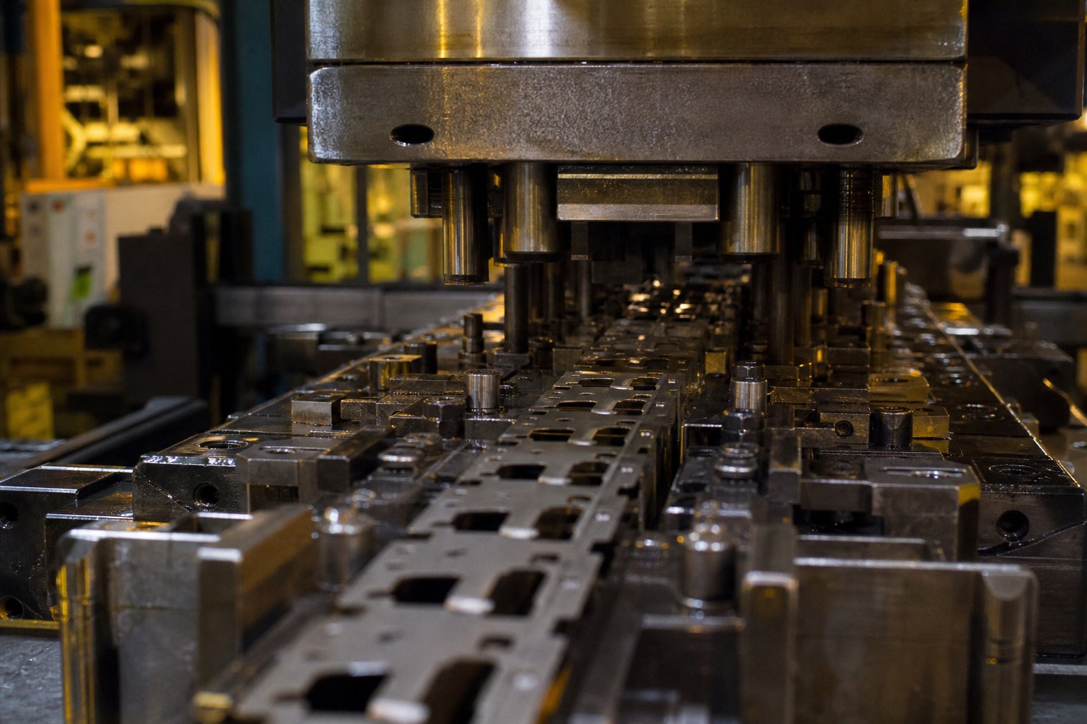
Controlled conditions during die tryout rarely reveal the full story. A bypass notch design might survive fifty sample hits without issue, but the automotive metal stamping process demands millions of cycles under continuous thermal loading, progressive wear, and material coil variation. High-volume production is where inadequate notch design exposes itself, not as a sudden catastrophic failure, but as a slow drift toward instability that shows up in scrap rates, dimensional spread, and unplanned downtime.
High-Volume Production and Cumulative Stress Effects
In industrial metal stamping for automotive brackets, connector housings, and structural reinforcements, press speeds commonly exceed 200 strokes per minute. At that pace, the carrier strip flexes at each bypass notch location hundreds of times every minute. Over a production run of 500,000 parts, the notch root has cycled through its stress range half a million times. Any notch geometry operating near its fatigue threshold will begin to deteriorate, not after one shift, but progressively across days and weeks of production.
The cumulative effect follows a predictable pattern. First, micro-cracks initiate at the notch root where the stress concentration factor is highest. These cracks are invisible to the naked eye during routine inspection. Second, the cracks propagate incrementally with each press stroke, reducing the carrier's effective cross-section at the notch. Third, the weakened carrier loses rigidity, allowing station-to-station force transmission to increase gradually. Fourth, dimensional drift appears in finished metal stamping components as the decoupling effect degrades.
This sequence explains why automotive stamping dies running high-strength steel often produce acceptable parts for the first 100,000 hits, then develop progressive quality issues. The notch root is exhausting its fatigue life. The science of stress concentration and work hardening behavior covered earlier predicts this timeline with reasonable accuracy if the material's fatigue properties and the actual Kt value are known.
Thermal effects compound the problem. At high press speeds, punch temperatures gradually rise due to repeated friction and deformation loads, and that heat conducts into the strip. A carrier strip running 10-15 degrees Celsius above ambient at the bypass notch location has slightly altered yield strength and elongation. The margins designed into the notch geometry at room temperature shrink under thermal loading, potentially pushing the notch root into plastic strain territory during each cycle rather than remaining elastic.
Diagnostic Indicators of Inadequate Bypass Notch Design
Experienced press operators often detect bypass notch problems before quality inspectors do, because the symptoms manifest as changes in how the die runs rather than immediate dimensional defects. The following observable symptoms on the press floor indicate bypass notch issues:
- Strip lifting between stations - The carrier strip rises off the die surface after a heavy blanking or piercing hit, indicating that snap-through forces are transmitting through an insufficiently deep notch rather than being absorbed locally.
- Inconsistent part dimensions at forming stations - Dimensional spread increases gradually over a production run, suggesting that carrier strip rigidity at the notch is changing due to fatigue crack growth or that the notch never provided adequate decoupling to begin with.
- Pilot pin shearing or bending - Pilot pins experience lateral loads they were not designed to handle because strip misregistration, caused by notch-related feeding instability, forces the pilots to correct positional errors beyond their capacity.
- Progressive edge cracking at notch locations - Visible cracks extending from the notch root toward the carrier center, indicating that the notch root radius is too tight for the material grade, or that notch depth exceeds what the material's fatigue endurance can support at the given production volume.
- Strip buckling during feed advance - The carrier collapses laterally at the notch location when the feeder pushes the strip forward, meaning the remaining ligament after notch depth is too narrow to resist the compressive feeding load without buckling.
- Station-to-station dimensional drift in one direction - Parts at downstream stations consistently shift in the same direction, suggesting that material flow through an adjacent bypass notch is asymmetric due to grain direction misalignment or uneven notch geometry on opposing carrier edges.
- Accelerated die wear at stations adjacent to notches - Forming inserts or cutting punches near a bypass notch wear faster than expected because the notch is failing to decouple forces, transmitting repeated shock loads into those stations.
Each of these symptoms maps back to specific scientific principles. Strip lifting points to inadequate snap-through attenuation, a notch depth problem. Pilot pin damage traces to feeding instability, a carrier rigidity problem. Edge cracking reveals fatigue failure at the notch root, a geometry-versus-material mismatch. The diagnostic path works backward from the observable symptom to the underlying parameter that needs adjustment.
When a tooling engineer encounters inconsistent dimensions on a stamped metal part produced in a progressive die, the first question should not be whether the forming punch is worn. It should be whether the bypass notch upstream of that station is still performing its decoupling function. Fundamental troubleshooting principles emphasize that parts must be accurately located and properly held before any forming work occurs. A degraded bypass notch undermines both of these prerequisites by allowing force coupling between stations that distorts strip position and releases holding pressure unevenly.
The diagnostic approach for metal stamped part quality issues follows a logical sequence. First, inspect the notch root under magnification for fatigue crack initiation. If cracks are present, the root radius needs to increase or the notch depth needs to decrease for the material grade in use. Second, measure the strip's actual deflection at the notch during a slow-speed press cycle. If the carrier visibly flexes beyond elastic recovery, the remaining cross-section is insufficient or the material has work-hardened past its useful ductility at that location. Third, compare pilot hole elongation upstream and downstream of the notch. Oval-shaped pilot holes downstream indicate that the notch is not absorbing transmitted forces and the strip is registering off-center at that station.
Production data reinforces these observations. In high-volume stamped metal parts programs, progressive die failures rarely originate from a single damaged component. Most problems develop gradually through wear accumulation, strip instability, and thermal effects during continuous production. Bypass notch degradation follows this same pattern. The notch does not fail suddenly. It loses effectiveness incrementally, and the downstream symptoms appear long before the root cause becomes visually obvious.
For engineers running automotive stamping dies at production volumes exceeding 500,000 parts per year, proactive notch inspection at defined stroke-count intervals prevents the gradual slide from stable production into scrap accumulation. The science provides the framework: know your material's fatigue curve, calculate the actual Kt at the notch root, estimate the cycle count to crack initiation, and schedule inspection before that threshold arrives. That's how first-principles knowledge translates into production floor reliability for every metal stamping component the die produces.
Engineering-Driven Bypass Notch Design for Production Excellence
Diagnostic symptoms on the press floor confirm what the science predicts: bypass notch specifications must be rooted in quantifiable mechanics, not inherited convention. The principles of stress concentration, material anisotropy, and controlled relief geometry form a coherent framework that applies to every stamping die, regardless of part complexity or production volume.
Key Engineering Principles for Bypass Notch Specification
Three pillars support every sound bypass notch decision in metal stamping dies:
- Stress distribution governs notch geometry - Root radius, depth, and width determine the stress concentration factor at the relief point. Sizing these parameters against the material's fatigue curve ensures the notch survives production volume without crack initiation.
- Material anisotropy dictates orientation - Grain direction relative to notch alignment controls crack propagation behavior and material flow patterns. Ignoring rolling direction when specifying notch placement introduces unpredictable fracture paths that undermine carrier reliability.
- Controlled relief isolates station forces - The notch must reduce carrier stiffness enough to decouple adjacent stations while preserving sufficient cross-section for stable feeding. This balance is material-specific, thickness-dependent, and production-volume-sensitive.
Together, these principles replace guesswork with engineering rationale. A die designer who understands why a 35% notch depth with a 1.5t root radius works for HSLA steel can confidently adapt that specification when material grade, thickness, or forming severity changes. That adaptability is the real value of science-driven die and stamping design: it scales to new applications without requiring a fresh round of trial-and-error tryout.
When bypass notch specifications are derived from stress concentration theory, material fatigue data, and anisotropic flow analysis rather than shop-floor tradition alone, every stamping die component in the strip layout performs its intended function across the full production lifecycle.
Partnering With Specialized Die Design Resources
Translating these principles into production-ready tooling requires more than theoretical knowledge. It demands experience with how stamping die components interact under real press conditions, across diverse materials, and at volumes where cumulative effects expose every marginal design choice. Engineers working on complex progressive dies with critical bypass notch requirements benefit from partnering with tooling specialists who bridge science and shop-floor reality.
When evaluating a metal stamping dies company overview, look for partners who demonstrate fluency in both the engineering fundamentals and the practical constraints of die stamping production. YICHEN connects tooling engineers to custom stamping die solutions where bypass notch design, material flow control, burr management, and clearance optimization are treated as integrated engineering challenges rather than isolated punch-and-die decisions. Their approach to dies and stamping reflects the same first-principles methodology covered throughout this article: define the stress state, match geometry to material behavior, and validate through production data.
The path forward for any engineer specifying bypass notches is clear. Ground your decisions in the mechanics of stress concentration and material response. Validate through diagnostic observation on the press floor. And when the application demands expertise beyond your current tooling capability, engage a partner whose engineering depth matches the complexity of your stamping die design requirements.
Frequently Asked Questions About Bypass Notches in Stamping Dies
1. What is the purpose of bypass notches in progressive stamping dies?
Bypass notches serve three core mechanical functions in progressive stamping dies. They control material flow by creating relief points that let sheet metal deform without excessive constraint from neighboring stations. They redistribute shear stress away from critical forming zones to prevent localized failure. And they reduce snap-through forces that cause strip lifting and mis-feed conditions. Essentially, they act as engineered stress boundaries that isolate deformation zones so each station operates independently without corrupting adjacent features.
2. How do you determine the correct bypass notch depth for different materials?
Notch depth is primarily driven by the material's elongation percentage and work hardening behavior. Mild steel with 28-42% elongation tolerates depths of 40-50% of carrier width because its ductility reserve prevents crack initiation at the notch root. High-strength steels with reduced elongation (12-24%) require shallower depths of 20-35% with larger root radii. Aluminum alloys need 30-40% depth with generous radii due to low fatigue endurance and galling tendencies. Stainless steel demands the most conservative approach (25-35% depth, root radius of 2.0t or greater) because its extreme work hardening rate causes local embrittlement at the notch root.
3. What is the difference between positive and negative bypass notches?
Negative bypass notches remove material from the carrier strip edge, creating localized flexibility that allows adjacent stations to deform independently. They reduce cross-sectional area and bending stiffness at that point. Positive bypass notches work the opposite way by adding material or leaving a protruding tab at the strip edge to create localized stiffening. Negative notches are used where force decoupling between stations is needed, while positive notches are applied where feed control and carrier rigidity require reinforcement at specific locations.
4. How does grain direction affect bypass notch performance in sheet metal?
Sheet metal exhibits anisotropic properties due to grain elongation during rolling. A bypass notch oriented parallel to grain direction propagates cracks more readily along grain boundaries, offering aggressive decoupling but shorter fatigue life. A notch perpendicular to grain direction resists crack growth but may restrict material flow during forming operations. Cold-rolled steel and stainless steel show strong anisotropic effects, while hot-rolled steel and copper are less sensitive. Engineers must confirm coil orientation relative to the feed axis and match notch placement to forming severity at adjacent stations.
5. What are the signs of inadequate bypass notch design during production?
Observable symptoms include strip lifting between stations after heavy blanking hits, gradual increase in dimensional spread at forming stations, pilot pin shearing from strip misregistration, visible edge cracking extending from notch roots, strip buckling during feed advance, and accelerated die wear at stations adjacent to notches. Each symptom maps to a specific engineering parameter: strip lifting indicates insufficient notch depth, pilot damage traces to feeding instability, and edge cracking reveals a geometry-versus-material mismatch. Specialized tooling partners like YICHEN can help diagnose these issues and translate corrective actions into optimized die designs.


