


What Is a Die Stamping Machine and Why It Matters
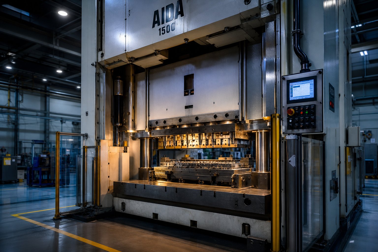
When you hear the term "die stamping machine," what comes to mind? If you picture a generic press slamming into metal, you're only seeing half the picture. A die stamping machine is not just a press and not just a die - it's the complete integrated system where a press frame and a purpose-built die set work together to convert flat sheet metal into finished parts through controlled force.
A die stamping machine is an integrated metalworking system that pairs a press frame with a matched punch-and-die set to shear, form, or draw sheet metal into net-shape components in a single stroke or a sequence of strokes.
That definition of stamping distinguishes this equipment from standalone presses sold without tooling and from dies sitting on a shelf waiting for a compatible machine. The value - and the complexity - lives in how the two halves unite into one production system.
Defining a Die Stamping Machine
Here's the fundamental principle: a ram driven by a mechanical, hydraulic, or servo drive delivers tonnage to a matched punch-and-die set mounted between the slide and the bolster plate. Depending on the operation, that single stroke can blank a flat profile from strip stock, pierce holes, bend flanges, or draw a deep cup shape. Progressive die systems advance a coil strip through multiple stations, performing a different operation at each stop until a completed part exits the final station.
You'll notice the term overlaps with several related phrases. A stamping press refers to the machine frame and drive - the force-generating half. A metal stamping machine is a broader industry label covering the same equipment. Die stamping narrows the focus to the system-level relationship between press and tooling. All three describe the same family of equipment, but "die stamping machine" emphasizes that the die is not an accessory - it's half the system.
Where Die Stamping Fits in Metalworking
If you're coming from a different corner of manufacturing, it helps to see where metal stamping sits relative to other processes:
- CNC machining removes material from a solid block to achieve complex geometries - ideal for low-to-medium volumes and tight tolerances, but slower and more wasteful of raw material at scale.
- Laser cutting profiles flat sheet with high precision, yet it only cuts - it cannot form bends, draws, or embossed features in a single operation.
- Casting pours molten metal into molds, suiting complex 3D shapes but requiring secondary machining and longer cycle times.
- Die stamping shapes room-temperature sheet metal at high speed with minimal waste, producing strong, repeatable parts in volumes ranging from thousands to millions per year.
A comparison from DureX Inc. highlights the tradeoff clearly: CNC machining wins on flexibility and tight tolerances for complex one-offs, while metal stamping wins on cost per part and speed once tooling is complete. The die stamping machine occupies the sweet spot where production volume justifies the tooling investment and part geometry suits sheet-metal forming.
Understanding this positioning matters because the machine you select - and the die you engineer for it - determines your per-part cost, quality ceiling, and production rate for years to come. Every decision downstream, from component design to drive type to maintenance schedule, flows from how well the press and die work together as a single system.
Core Components Inside a Die Stamping Machine
Knowing that the press and die form a single system is one thing. Knowing what's actually inside that system - and what each part does - is what separates confident troubleshooting from guesswork. Every stamping press machine contains dozens of interacting components, split between the press side (the force generator) and the die side (the metal stamping tool that shapes raw material). Let's break both halves open.
Press Frame and Drive Components
The frame is the skeleton. Two designs dominate the market:
- C-frame (gap frame) - Shaped like an open "C," giving easy access to three sides of the die area. Compact and economical, but prone to angular deflection under heavy or off-center loads.
- Straight-side frame - Vertical columns on both sides eliminate angular misalignment, providing superior die life and part accuracy for higher-tonnage or precision work.
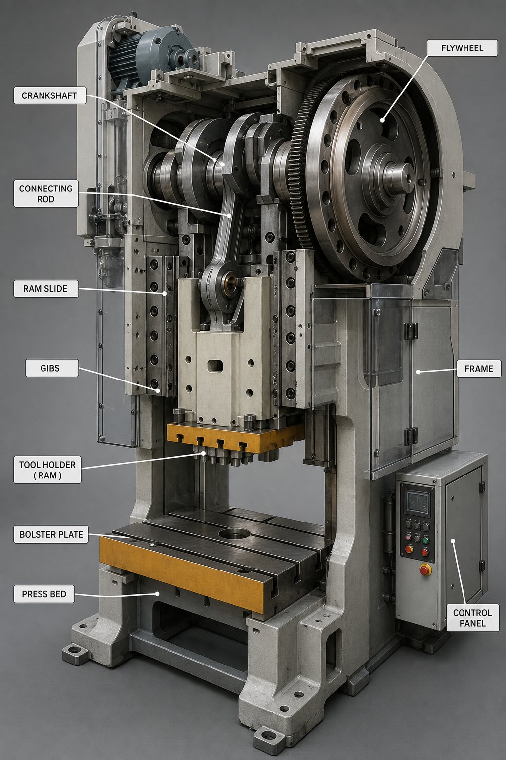
Mounted on (or within) that frame, the drive train converts rotary motion from an electric motor into the linear force that cycles the ram. In a mechanical stamping press, the motor spins a flywheel that stores kinetic energy. When the operator triggers a cycle, a clutch engages to transfer that energy through a crankshaft or eccentric shaft to the slide. A brake holds the ram in position the moment the clutch disengages. This clutch-brake system governs not only cycle timing but also operator safety - stopping time determines how fast the press can run and how close hands can safely be to the point of operation.
The ram (slide) travels vertically along precision gibs and delivers tonnage to whatever tooling sits below it. Beneath the ram, the bolster plate provides a flat, rigid mounting surface for the lower die half, typically featuring T-slots or tapped holes for clamping. Together, these stamping press parts form the force-delivery backbone of the machine.
Die Set Components and Their Functions
If the press is the engine, the die set is the transmission - it converts raw force into precise geometry. A complete metal stamp die assembly includes far more than a punch and a hole:
- Upper and lower die shoes - Thick steel plates that carry all cutting and forming components. They bolt to the ram and bolster, respectively, serving as the structural foundation of the die.
- Guide pins and bushings - Precision-ground posts and sleeves that align the upper and lower shoes every cycle, maintaining tight clearances between punch and die blocks.
- Punch and die blocks - The hardened tool-steel inserts that actually cut, bend, or form the metal. Clearance between them determines burr height and edge quality.
- Strippers - Spring-loaded (or positive/fixed) plates that pull the strip off cutting punches after each stroke. Without them, the metal collapses around the punch shank and jams the next cycle.
- Pilots - Small pins that enter previously pierced holes to register the strip in exact position before the next hit. They're the unsung heroes of progression accuracy.
- Feed mechanisms - Roll feeds (intermittent driven rollers), gripper feeds (slide-actuated clamps), or servo feeds (digitally controlled rollers) that advance coil stock a precise distance between strokes.
Imagine all of these parts working at 200 strokes per minute - each component must locate, cut, strip, and advance material in a fraction of a second. That's why this stamping equipment demands precision manufacturing and disciplined maintenance from day one.
Component Reference Table
| Component | Location | Primary Function |
|---|---|---|
| Frame (C-frame or straight-side) | Press side | Structural support; resists deflection under load |
| Flywheel | Press side | Stores kinetic energy from motor between strokes |
| Clutch-brake system | Press side | Engages/disengages flywheel energy; stops the ram |
| Ram / Slide | Press side | Delivers linear force to upper die half |
| Bolster plate | Press side | Supports and locates lower die half |
| Upper & lower die shoes | Die side | Carry all cutting/forming components |
| Guide pins & bushings | Die side | Align upper and lower die halves each stroke |
| Punch & die blocks | Die side | Perform cutting, forming, or drawing operations |
| Stripper plate | Die side (upper) | Strips material off punches after cutting |
| Pilots | Die side (upper) | Register strip position for accurate progression |
| Feed mechanism (roll/gripper/servo) | Press side (auxiliary) | Advances coil stock a set distance per stroke |
With every one of these parts mapped, the next logical question is: how do they constrain each other? A die designer can't choose station count, strip width, or progression pitch without knowing the press's shut height, bed area, and available tonnage curve - and vice versa. That interplay between the two halves is where systems either perform or fail.
How the Die and Press Work Together as a System
A die sitting on a shelf is just precision steel. A metal press without tooling is just controlled force with nowhere to go. Neither produces parts alone. The real performance - or failure - of a die stamping press lives in the interface where these two halves meet. Get that interface wrong, and you'll burn through tooling, drift on quality, or damage the machine itself.
Most resources treat the die and the press as separate topics: one article covers die design, another covers press specs. In production, they're a married system. Part geometry drives die complexity, die complexity drives press requirements, and available press capabilities loop back to constrain what the die engineer can do. Understanding that loop is what separates a well-matched metal stamping press machine from an expensive mismatch.
How Die Design Dictates Press Requirements
Every decision the die engineer makes translates into a demand on the press. Imagine you're designing a progressive die for an automotive bracket with six stations - two piercing, one lance-and-form, two draw stations, and a final cutoff. Each of those choices creates specific requirements the press must satisfy:
- Number of stations and strip width - More stations mean a longer die, which demands a wider bolster (left-to-right bed dimension). A six-station die on 3-inch progression pitch needs at least 18 inches of working length, plus space for scrap cutters and end stock.
- Progression pitch and feed length - The distance the strip advances per stroke dictates feed mechanism travel and the timing window available for material advance. Larger pitch on a high-speed press compresses the feed window.
- Part geometry and draw depth - Deep forms require longer stroke length so the ram travels far enough to fully engage the draw, plus sufficient daylight (open height) for part extraction.
- Die shut height - This is the overall height of the closed die assembly. It must fall within the press's available die-height space. As MetalForming Magazine explains, if die shut height exceeds the press's maximum die-height space, the die closes fully before the ram reaches bottom dead center - stretching the frame and potentially damaging both the die and the press.
Shut height deserves special attention because it's where confusion causes real damage. Press shut height is the distance from the bottom face of the ram to the top of the press bed with the ram at bottom dead center and adjustment fully up. Die height - the usable space - subtracts the bolster plate thickness from that number. The die's closed height must fit between the minimum and maximum die-height values, accounting for ram adjustment range. Miss that window, and you're either unable to mount the die or generating catastrophic overloads on every stroke.
Sounds like the die calls all the shots? Not quite. The press pushes back.
How Press Capabilities Shape Die Engineering
The press machine for metal stamping isn't a passive host - its characteristics actively shape what the die engineer can and cannot do. Three press-side factors influence die design most heavily:
Tonnage curves, not just rated capacity. A 400-ton metal stamping press doesn't deliver 400 tons everywhere in its stroke. On a mechanical press, full rated tonnage is only available near bottom dead center - typically within the last 6 to 12 mm of travel. Industry guidance on mechanical press loading shows that a draw operation starting 3 inches above bottom on a 2000-ton press may only have roughly 1000 tons available at that point. The die engineer must map forming loads against the press's actual tonnage curve, not the nameplate number. If the heaviest forming station demands peak force high in the stroke, the die either needs redesigning - or a different press.
Slide speed and energy per stroke. Available energy depends on flywheel speed and allowable slowdown per cycle. A press stamping operation that draws material through a long working distance consumes more energy than a shallow blanking hit at the same tonnage. If the die's energy demand exceeds what the flywheel can deliver in a single stroke, the press stalls or slows beyond acceptable limits.
Bed dimensions and bolster patterns. T-slot spacing, tapped-hole patterns, and bolster width physically limit where you can clamp the die. An oversized die that hangs past the bolster edges introduces unsupported loading. Conversely, a die that's too narrow for the press may create offset-loading problems - a condition where one side of the press bears significantly more force than the other, accelerating gib wear and skewing ram parallelism.
Key Matching Criteria for a Press-and-Die System
When evaluating whether a die and a press for metal stamping will function as a reliable system, these criteria must align:
- Tonnage at required stroke position - Not just peak rated capacity, but usable force at the exact point in the stroke where forming loads peak.
- Shut height range - The die's closed height must fall within the press's minimum-to-maximum die-height window after accounting for bolster thickness and any risers.
- Stroke length - Must provide enough travel for full die engagement plus safe part clearance during the return stroke.
- Bed size (left-right and front-back) - Must accommodate die footprint without unsupported overhang or excessive offset loading.
- Feed window timing - The press must provide enough crank-angle dwell near top dead center for the feed mechanism to advance the strip without colliding with pilots or strippers.
- Energy per stroke - Total work required (tonnage multiplied by working distance across all stations) must stay within the press's energy budget at the planned production speed.
- Offset-load tolerance - Load distribution across the die must respect the press's left-to-right balance limits, typically within a 60/40 percent split.
Miss any single criterion, and you won't necessarily see immediate failure. You'll see gradual quality drift, accelerated guide wear, premature punch breakage, or drivetrain stress that shortens the press's service life. The system doesn't announce a mismatch with a dramatic crash - it whispers through burr-height creep and dimensional wander until someone finally asks why the tooling keeps wearing out.
With the die-press relationship mapped, the next question becomes practical: which combination of press drive and die configuration actually suits your production scenario? The answer depends on volume, part complexity, and the type of force delivery your operations demand.
Types of Die Stamping Machines and When to Use Each
The press-die relationship sets the rules, but which combination do you actually build around? That depends on two independent variables: how the press generates force (drive type) and how the die organizes operations (die configuration). Pair them correctly and you get a production system tuned to your volume, part complexity, and cost targets. Pair them poorly and you'll fight the machine on every run.
Press Drive Types Compared
Three drive architectures cover the vast majority of applications. Each delivers force differently, which shapes cycle speed, flexibility, and the kinds of tooling it can host.
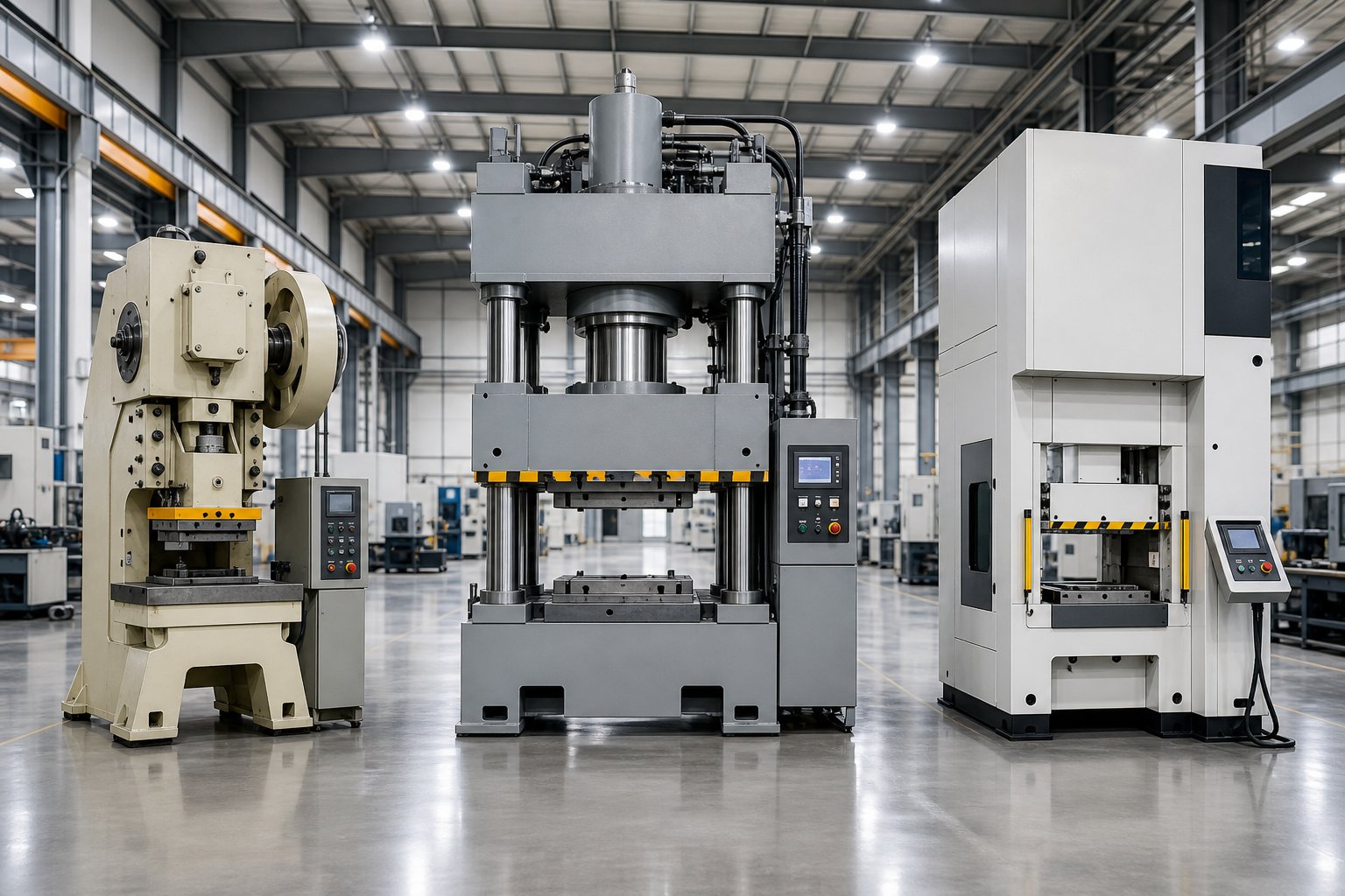
Mechanical (flywheel-driven) - A motor spins a flywheel that stores kinetic energy. When the clutch engages, a crankshaft converts that stored energy into a fixed-length stroke. The result: fast, repeatable cycling - often 50 to 65 strokes per minute at moderate tonnage. Force peaks near bottom dead center, making these presses ideal for blanking, piercing, and shallow forming where the working distance is short. A high speed stamping press running progressive tooling at 200+ SPM is almost always mechanical.
Hydraulic - A pump pressurizes fluid to drive a piston, delivering adjustable force throughout the entire stroke. Cycle speeds are slower (typically 30 to 35 SPM at 100 tons), but a hydraulic stamping press provides full tonnage at any point in the ram's travel. That makes it the go-to choice for deep drawing, thick high-strength steels, and operations requiring dwell time at the bottom of the stroke.
Servo-driven - A programmable servo motor replaces the flywheel entirely, giving engineers full control over stroke length, speed profile, and dwell at any position. You can program pendulum motion for shallow draws, slow the ram mid-stroke for difficult forming, or run a short-stroke cycle at speeds rivaling mechanical presses. The tradeoff is higher initial cost and more sophisticated controls.
| Criteria | Mechanical Press | Hydraulic Press | Servo Press |
|---|---|---|---|
| Cycle speed (SPM at 100T) | 50-65+ | 30-35 | Variable (up to 50+) |
| Tonnage consistency | Peak at BDC only | Full force throughout stroke | Full force at any programmed point |
| Energy efficiency | High at sustained speed | Continuous pump draw | 15-20% better than hydraulic |
| Flexibility | Fixed stroke profile | Adjustable stroke and dwell | Fully programmable motion |
| Best-fit applications | High-volume blanking, piercing, progressive dies | Deep drawing, thick material, low-to-medium volume | Complex forming, AHSS, mixed production |
Die Configurations and Their Applications
The die side of the equation determines how many operations happen per stroke - and how the workpiece moves between them. From simplest to most complex:
- Single-station dies - One operation per stroke: a blank, a pierce, or a form. Simple, inexpensive, and fast to build. Best for low-complexity parts or secondary operations on pre-cut blanks.
- Compound dies - Multiple cutting operations in a single stroke (for example, blanking the outer profile and piercing interior holes simultaneously). They deliver tight positional accuracy between features because everything cuts in one hit, but they're limited to flat operations in one plane.
- Progressive dies - A coil strip advances through sequential stations, each performing a different operation - piercing, lancing, forming, drawing, cutoff - until a finished part drops at the final station. Progressive die stamping is the workhorse of high-volume production. A progressive stamping press running a well-designed progressive die can produce thousands of completed parts per hour with minimal manual handling.
- Transfer dies - Individual blanks (rather than a continuous strip) are mechanically transferred between independent die stations. A transfer stamping press handles larger parts or geometries too complex for strip-based progression. Transfer dies also waste less material because there's no carrier web connecting parts through the strip.
Each step up in die complexity demands more from the press: more stations mean larger bed area, tighter feed timing, higher cumulative tonnage, and more sophisticated controls. A progressive stamping die running at high speed needs a press with excellent ram repeatability and a generous feed window; a transfer setup needs integrated mechanical fingers or servo grippers synchronized to the press cycle.
Matching Machine Type to Production Need
Which combination actually makes sense for your scenario? Think in tiers:
- Prototype and short-run (under 10,000 parts) - Hydraulic press with single-station or compound dies. Low tooling cost, quick changeover, adjustable forming parameters. Speed doesn't matter when you're dialing in geometry.
- Medium volume (10,000 to 500,000 parts) - Mechanical or servo press with compound or short progressive dies. Cycle speed starts to drive cost-per-part, and dedicated tooling pays for itself. A servo press adds flexibility if you're running mixed part numbers on the same machine.
- High volume (500,000+ parts) - Mechanical high speed stamping press paired with a progressive die press configuration or a dedicated transfer line. At this scale, every fraction of a second per cycle and every gram of scrap material hits your bottom line. Progressive die stamping dominates here because it maximizes strokes per minute while minimizing labor touches.
The right pairing isn't always the most advanced option - it's the one where drive type, die configuration, and production volume reinforce each other rather than working at cross purposes. And once you've selected the right class of machine, the next challenge becomes quantitative: how much tonnage do you actually need, and what other specs separate a well-sized press from an expensive guess?
Calculating Tonnage and Selecting the Right Machine
You've identified the right drive type and die configuration for your application. The next question is deceptively simple: how much force does the press actually need to deliver? Undersized tonnage overloads the machine, damages tooling, and produces inconsistent parts. Oversized tonnage wastes capital and floor space. The answer lives in a straightforward formula - but applying it correctly across a multi-station progressive die requires careful bookkeeping.
Understanding Tonnage Requirements
For any cutting operation - blanking, piercing, notching - the tonnage calculation follows a core relationship:
Required Tonnage = Cut Perimeter (in.) x Material Thickness (in.) x Material Shear Strength (tons/in.²)
That's it at the conceptual level. The cut perimeter is the total length of the edge being sheared, material thickness is the stock gauge, and shear strength is a property of the metal itself. Harder materials demand more force per unit of cut. A stainless steel part with the same geometry as a mild steel part will require significantly higher tonnage because stainless has roughly 1.5 to 2 times the shear strength.
A few practical realities complicate the clean formula:
- Dull tooling compensation - The formula uses full material thickness to account for wear. In reality, shearing occurs partway through the stock (visible as the shear band on any stamped edge). Sharp punches reduce actual force, but engineers size the press for worst-case conditions to avoid overloads as tooling wears between sharpening cycles.
- Forming and drawing operations - Bending, coining, and drawing don't follow the same perimeter-based formula. Drawing tonnage uses ultimate tensile strength rather than shear strength because the shell walls are in tension during the draw. Blank holder pad pressure, nitrogen springs, and any driven cams in the die add further load on top of the forming force.
- Cumulative station loads - In a progressive die, the press hits every station simultaneously. That means you add the tonnage from each piercing station, each forming station, every spring stripper, every lifter pin, and the final cutoff together to get total die load. A 15-station progressive die might individually require modest force at each station, but the sum can easily exceed 100 tons.
This cumulative effect is why a sheet metal stamping press running progressive tooling often needs more capacity than you'd guess from looking at the finished part alone. Engineers typically add a 20 to 30 percent safety margin on top of calculated totals to accommodate material property variation, tooling wear, and any stations added during future engineering changes.
There's another factor most buyers overlook: energy. A steel stamping press can have enough rated tonnage yet still stall at bottom dead center if the operation demands more energy than the flywheel can deliver in a single stroke. Deep draws that work the material over a long distance consume significantly more energy than shallow blanking cuts at the same force. Sizing both tonnage and energy prevents the press from jamming under load - a common failure mode that damages both the machine and the die.
Selection Criteria Beyond Tonnage
Tonnage gets the headlines, but a press stamping machine that matches your force requirement can still fail your production goals if other specifications don't align. Think of tonnage as table stakes - necessary but not sufficient. Here's what else matters, and how the answer shifts depending on your production volume:
- Low volume (under 10,000 parts)
- Bed size - Must accommodate your die footprint, but flexibility for multiple die sets matters more than optimizing for one tool.
- Stroke length - Generous stroke supports varied part depths across different jobs; a small stamping press with limited stroke restricts future tooling options.
- SPM (strokes per minute) - Less critical; changeover time and setup flexibility outweigh raw cycle speed.
- Die protection - Basic misfeed detection and tonnage monitoring protect tooling investment, especially when running short batches where operators may be less familiar with specific dies.
- Feed window - Standard feed timing is acceptable; precision timing becomes critical only at higher speeds.
- Medium volume (10,000 to 500,000 parts)
- Bed size - Sized to your primary die with room for future progression additions (extra stations for quality improvements or design changes).
- Stroke length - Matched to your deepest forming station plus clearance for part ejection.
- SPM - Moderate speeds (40-80 SPM) where cycle time starts materially affecting cost per part.
- Die protection - Misfeed sensors, slug detection, and part-out verification become standard requirements to prevent scrap runs and tooling crashes.
- Feed window - Tighter feed timing needed to maintain progression accuracy at higher speeds without strip buckling.
- High volume (500,000+ parts)
- Bed size - Precision-matched to the die footprint with optimized load balance across the press bed; no wasted capacity.
- Stroke length - Minimized to the shortest travel that safely clears the part, maximizing available SPM.
- SPM - High speed metal stamping demands 150 to 400+ strokes per minute; every SPM gained translates directly to throughput and profit.
- Die protection - Full sensor suite including tonnage monitors, acoustic crack detection, in-die part measurement, and automatic shutdown on fault. At high volume stamping speeds, a single missed misfeed can destroy stations before anyone reacts.
- Feed window - Servo feeds with crank-angle synchronization; feed timing precision measured in degrees of press rotation, not milliseconds.
One pattern emerges across all tiers: as volume increases, every specification tightens. Precision stamping press machines running millions of parts demand exact matching between press specs and die requirements - there's no margin for "close enough." The press bed must center the die load to prevent deflection drift. The stroke must be short enough to reach target SPM without exceeding slide velocity limits at draw stations. The feed window must be wide enough for the progression pitch without conflicting with pilot engagement timing.
Sizing a die stamping machine correctly means running these calculations in parallel - tonnage, energy, bed fit, stroke clearance, speed feasibility, and feed timing - and confirming that all six align before committing to a purchase order. Skip one, and you'll discover the gap on the production floor, where fixing it costs ten times more than catching it on paper.
The numbers tell you which machine to buy. But numbers alone don't produce parts - a complete workflow connects part design through die engineering, trial runs, and inspection before the press ever cycles at production speed.
The Complete Workflow from Part Design to Production
A perfectly sized press and a well-matched die configuration don't materialize overnight. Before the die stamping machine ever cycles at production speed, a metal part travels through a disciplined sequence of engineering stages - each one either building toward first-article success or quietly embedding a defect that won't surface until thousands of parts later. Most resources treat these stages in isolation: one guide covers part design, another covers die engineering, and a third covers tryout procedures. In reality, they form a single continuous chain where decisions in one phase constrain every phase that follows.
Part Design and Feasibility Analysis
Every progressive die stamping process begins not at the press, but at the CAD screen - with a part geometry that must be evaluated for manufacturability before anyone commits tooling dollars. Design for Manufacturability (DFM) in stamping revolves around a handful of critical constraints:
- Bend radii - Internal bend radius should equal or exceed 1.0 to 1.5 times the material thickness. Go below that threshold and you risk cracking at the bend line, especially when the bend runs parallel to grain direction.
- Minimum hole diameters - Pierced holes generally need a diameter at least equal to material thickness for round holes (1.5x for non-round shapes). Smaller features overload the punch and shorten tool life dramatically.
- Grain direction - Bends oriented perpendicular to the rolling grain resist cracking far better than parallel bends. Strip layout must account for this, particularly when selecting progressive stamping materials like high-strength steels or stainless alloys that crack more readily along grain.
- Draft and draw ratios - Deep-drawn features require controlled material flow. Wall thinning, wrinkling risk, and required blank holder force all stem from the draw ratio established at the design stage.
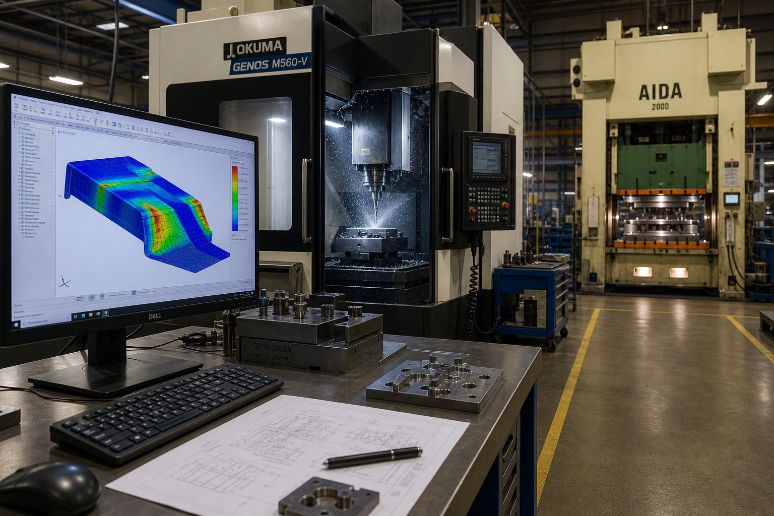
How do engineers validate these decisions before cutting steel? CAE simulation. Finite Element Analysis (FEA) models the forming process digitally - predicting thinning, wrinkling, and springback with enough accuracy to adjust geometry or station sequencing before any physical tooling exists. This virtual tryout step eliminates the most expensive category of engineering changes: the ones discovered after the die is already built.
Die Engineering and Validation
Once feasibility is confirmed, the progressive die and stamping tool design moves into detailed engineering. This stage transforms an approved part concept into a fully defined die set - hundreds of individual components that must work in concert at high speed.
The critical deliverables include:
- Strip layout optimization - Engineers define how the part nests on the coil strip, sequence operations across stations, and determine progression pitch. A well-designed strip layout maximizes material yield while maintaining carrier strip integrity throughout the progressive stamping process.
- Station sequencing - Piercing pilot holes first, then progressive forming and cutting operations, with idle stations reserved for future engineering changes. Each station's force contribution feeds back into the press tonnage calculation.
- Material flow simulation - CAE tools model how metal moves through draw and form stations, predicting springback compensation values that get built directly into the die geometry.
- Tool steel selection - Punch and die inserts typically use high-speed steels (SKH9 at HRC 60-62) or tungsten carbide for extreme wear resistance, while die shoes use medium-carbon steel for shock absorption. The right material at each position balances hardness against toughness.
- Precision machining - Wire EDM, sinker EDM, CNC milling, and precision grinding produce die components to micron-level tolerances. The fit between punch and die cutting edges - measured in thousandths of a millimeter - determines burr height, edge quality, and ultimate die life.
Progressive die metal stamping tooling at this level isn't a commodity. It's a precision instrument engineered for millions of cycles, where each component's accuracy compounds into overall system performance.
Trial Runs and Production Qualification
The die is assembled, mounted in the press, and aligned. What happens next separates competent tooling programs from chaotic ones - the tryout phase bridges theoretical design and production reality.
A structured tryout sequence typically follows these steps:
- Inching and interference check - The press cycles at extremely slow speed to verify mechanical clearance through all stations. Feed engagement, pilot entry, and stripper timing are confirmed before any full-speed hit.
- First-hit sampling - Initial parts are produced and immediately measured on a Coordinate Measuring Machine (CMM). These samples reveal actual springback behavior, dimensional deviations, and surface quality issues.
- Iterative die adjustment - Based on CMM data, toolmakers perform micron-level corrections: grinding forming blocks to compensate springback, adjusting punch-to-die clearance for cleaner shearing, or modifying pilot positions for better strip registration.
- Capability run - Once dimensions hold within specification, a short production run (often 1,000 to 5,000 parts) is analyzed statistically. Process capability indices like Cpk confirm the die produces parts within tolerance consistently - not just on the first few samples.
Only after capability validation does the die receive formal release for mass production. Skipping or compressing this phase is one of the most common reasons progressive stamping dies fail early - dimensional problems masked during a handful of hand-checked samples emerge as systematic defects at volume.
This end-to-end workflow - feasibility analysis, CAE simulation, precision die machining, structured trial runs, and dimensional inspection - represents the complete progressive die stamping services chain. Suppliers who manage every stage under one roof eliminate the handoff gaps where quality problems hide. YICHEN, for example, connects each phase into a single accountable process: from initial DFM review and forming simulation through CNC die manufacturing, in-house tryout, and CMM-verified qualification - giving manufacturers and tooling engineers a direct path from research to RFQ-ready custom stamping die solutions.
For any stamping plant scaling from prototype to production, the lesson is consistent: each workflow stage exists to catch problems while they're still inexpensive to fix. A $500 simulation adjustment prevents a $50,000 die rework. A disciplined tryout prevents six months of quality firefighting on the production floor.
The workflow gets parts to production - but what happens once the die is running? Setup procedures, changeover efficiency, and safety systems determine whether that carefully engineered tooling delivers its full potential or degrades under operational missteps.
Setup, Changeover, and Safety Systems Explained
Engineering and trial runs bring the die to readiness. But every time that tooling goes into the press - whether for the first run or the fiftieth - the setup process either preserves the precision built into the system or quietly erodes it. For the stamping press operator responsible for getting the die running safely and accurately, setup isn't a formality. It's where operational discipline meets tooling investment.
Die Installation and Setup Procedures
A clean, systematic die change protects both the operator and the tooling. Imagine you're mounting a progressive die into a 200-ton straight-side press. Here's the sequence that experienced die setters follow:
Bolster preparation. Before the die arrives, the bolster plate is cleaned of debris, slugs, and residual lubricant. T-slots are inspected for burrs that could prevent the die from seating flat. Any high spots on the bolster translate directly into uneven loading - and uneven loading kills die alignment over thousands of cycles.
Die clamping. Mechanical clamps with heel blocks remain the standard in most shops, but hydraulic clamping systems are gaining ground in facilities running frequent changeovers. Hydraulic clamps apply uniform force across the die shoe, eliminate the variability of hand-torqued bolts, and can be engaged or released in seconds - cutting what used to be a 30-minute clamping task down to under a minute.
Shut height adjustment. With the die seated, the ram lowers to close the die onto its stop blocks. As MetalForming Magazine's die-setup guide emphasizes, the setup person performs a stop-block lead reading to confirm the die is fully closing. On presses with motorized shut-height adjustment, the counterbalance pressure must also be set correctly - neutralizing the weight of the ram and upper die assembly so the adjustment motor doesn't fight gravity. Industry best practice requires the upper die weight be stamped directly onto the die so operators can reference the press's counterbalance chart and set the correct pressure every time.
Feed setup and timing. The coil feed mechanism must advance material exactly one progression pitch per stroke. But timing is just as critical as distance. Pilot release - the moment the feed rollers unclamp the strip so pilots can register it - must be set so the bullet nose of the pilot enters the strip before the rollers open, but the full pilot diameter doesn't engage until the strip is fully released. Set the release too early, and the strip drifts from the weight of the takeup loop. Set it too late, and the pilots fight the rollers, elongating pilot holes and causing misfeed.
Pilot engagement verification. With feed timing set, the operator inches the press through several strokes and visually confirms that pilots enter cleanly, the strip advances without buckling, and strippers pull the material off cutting punches without dragging. This is the moment to catch interference before running at production speed.
First-piece inspection. The initial parts off the die are measured against the dimensional print. Only after confirming conformance - and running the strip fully through all stations to confirm cumulative accuracy - does the setup qualify for production release.
This entire sequence can take anywhere from 45 minutes to several hours on a complex industrial metal stamping machine. That's why Quick Die Change (QDC) systems exist. A full QDC setup integrates hydraulic clamping, automatic counterbalance adjustment, preset shut-height databases, and roller-style die carts that slide tooling into position on the bolster. Facilities running QDC can reduce changeover from 2-3 hours to under 10 minutes - a transformation for any industrial stamping machine running multiple part numbers per shift. The economics are straightforward: every minute spent on changeover is a minute the press isn't producing parts. For high speed stamping operations cycling at 200+ SPM, even a 15-minute reduction in changeover translates to thousands of additional parts per shift.
Safety Systems and Modern Controls
A die stamping machine concentrates enormous force into a small working area at high speed. The safety systems surrounding it serve a dual purpose: protecting people from the press, and protecting the press and die from operational errors that cause catastrophic crashes. Both concerns demand the same infrastructure.
Consider what happens during automatic stamping at full production speed. The strip feeds, the ram descends, cutting and forming forces peak, and the ram returns - all within a fraction of a second. If the material misfeeds by even a few millimeters, pilots can't register the strip correctly. The next stroke punches into the wrong location, potentially driving a forming punch into a cutting station edge. The result: broken punches, cracked die blocks, and hours of unplanned downtime.
Modern electro mechanical stamping presses address this through layered sensing and control systems. Here are the essential safety devices and their functions:
- Light curtains - Arrays of infrared transmitters and receivers that detect any object entering the die area. When the sensing field is broken, control-reliable circuitry commands an immediate press stop. Proper application requires calculating the safety distance - accounting for press stopping time, control response time, and brake-monitor setting - to ensure the ram halts before a hand can reach the point of operation.
- Two-hand controls - Require the operator to simultaneously press two palm buttons spaced far enough apart that both hands are guaranteed outside the die area when the stroke initiates. Common on manual-feed operations where light curtains would interfere with part loading.
- Misfeed detection sensors - Proximity or photoelectric sensors that confirm the strip advanced the correct distance before allowing the next stroke. If the feed falls short or overfeeds, the press stops before damage occurs.
- Slug detection - Sensors beneath the die that verify cut slugs have dropped clear of the die cavity. A retained slug can stack under a punch, causing double-material hits that crack tooling.
- Part-out sensors - Confirm the finished part has ejected from the die before the next cycle. A retained part in a forming station creates the same double-material condition as a retained slug.
- Tonnage monitors - Load cells embedded in the press frame that measure actual force on every stroke. A sudden tonnage spike signals a misfeed, double-hit, or tooling failure. A gradual increase over time signals dulling tools approaching their sharpening limit. Either way, the system can stop the press or alert the operator before damage compounds.
- Programmable limit switches (PLS) - Electronic cams that trigger auxiliary functions at precise points in the press stroke, measured in degrees of crank rotation. They control feed engagement, pilot release, air blow-off for part ejection, and die-protection sensor enable/disable windows.
- Brake monitors - Devices that measure the elapsed time from stop command to actual ram halt. If stopping time exceeds the preset maximum (indicating brake wear), the press faults and will not cycle until maintenance restores braking performance. This directly protects the validity of light-curtain safety distances.
In a modern stamping automation environment, all of these sensors and devices feed into a PLC (Programmable Logic Controller) that executes safety logic in real time. An HMI (Human-Machine Interface) touchscreen gives the operator visibility into sensor status, fault history, tonnage trends, and production counts - consolidating what used to require a dozen individual gauges into a single integrated display. The PLC enforces interlocks: the press cannot cycle unless all die-protection sensors confirm ready status, the light curtains are clear, and the brake monitor reads within limits.
This architecture does more than prevent injuries. It prevents the kind of tooling crashes that turn a $200 misfeed incident into a $20,000 die repair. For a stamping press operator running an expensive progressive die, the safety system is also the tooling insurance system - every sensor that catches an error before the next stroke is protecting weeks of die-room labor embodied in those hardened steel components.
Safety and setup discipline keep the machine running correctly today. But what about next month, or next year? The wear patterns accumulating in every clutch plate, gib face, and cutting edge right now are quietly determining whether this tooling produces its next million parts - or fails at half that number.
Maintenance Practices That Extend Stamping Machine Lifespan
Those wear patterns don't announce themselves with alarms. They show up as a slow, silent drift - burr height creeping up a few thousandths, dimensions wandering toward tolerance limits, cycle-to-cycle force readings climbing on the tonnage monitor. By the time a part fails inspection, the damage has been compounding for weeks. Preventive maintenance exists to catch that drift early, when a $50 sharpening or a $10 grease cartridge prevents a $20,000 die rebuild or an unplanned shift of downtime.
The challenge with stamping machinery is that two separate systems - press and die - wear simultaneously but on different schedules. Neglect either one, and the other suffers. A press with worn gibs allows the ram to drift off-parallel, which accelerates uneven die wear. A die with dull cutting edges demands more tonnage per stroke, which overloads clutch-brake components and shortens press life. Maintaining both halves as a unified system is what separates stamping machines that produce millions of quality parts from those that limp along between emergency repairs.
Press Maintenance Essentials
Mechanical stamping presses store and release enormous energy every cycle. That energy passes through bearings, gears, gibs, and clutch-brake surfaces - all of which wear incrementally with use. A complete maintenance guide from JDM Presses emphasizes that proper lubrication and regular inspection are the primary cost-saving measures for any production team.
Here's where the effort goes:
- Lubrication - Slide gibs require grease at every shift start to prevent metal-to-metal contact that scores the ram guides. The clutch-brake system needs oil-pressure lubrication daily; without it, friction surfaces glaze and stopping time degrades - which directly compromises operator safety and die-protection response. Main bearings and the crankshaft journals depend on circulating oil systems with inline filters. Clogged filters or contaminated oil accelerate bearing wear exponentially.
- Drive train inspection - Belts, gears, and flywheel keys transmit all motor energy to the ram. Belt tension should be checked weekly; a slipping belt wastes energy and causes inconsistent stroke velocity. Gear teeth on metal presses should be inspected for pitting or spalling during scheduled shutdowns.
- Ram parallelism - Over time, gib wear allows the slide to tilt slightly. Even 0.001 inches of tilt across a 24-inch bed creates uneven clearance distribution in the die, causing one side to cut cleanly while the other produces excessive burrs. Annual parallelism checks - measuring with dial indicators at multiple bed positions - catch this drift before it damages tooling.
- Electrical and pneumatic systems - Solenoid valves controlling the clutch-brake must respond within milliseconds. Worn solenoids introduce latency that extends stopping time. Pneumatic systems controlling balancers and air cushions need daily water drainage from air lines; moisture in pneumatic circuits causes erratic pressure and unreliable brake performance.
One often-overlooked principle from operating an industrial metal press: keep it clean. A spotless press allows operators to immediately identify oil leaks, air leaks, and fractures that would otherwise hide under grime. If you can't see the problem forming, you can't stop it from growing.
Die Maintenance and Sharpening Cycles
The die wears differently from the press because it contacts the workpiece material directly. Every stroke shears, bends, or draws metal against hardened tool-steel edges - and those edges gradually round over regardless of material grade. The question isn't whether the die will need maintenance. It's whether you catch wear indicators early enough to sharpen rather than replace.
Recognizing wear before it becomes failure:
- Burr height increase - The earliest measurable signal. When burrs on stamped parts grow from an acceptable 0.003 inches to 0.005 inches or above, cutting edges have dulled past their effective threshold. Continued running accelerates punch breakage because the press must deliver more force to push through the rounded edge.
- Dimensional drift - Worn guide pins and bushings allow the upper and lower die halves to shift slightly relative to each other. Feature-to-feature dimensions on the stamped part drift as a result. By the time you see this on a CMM report, the guides have been degrading for thousands of strokes.
- Increased tonnage readings - Tonnage monitors reveal dull tooling before the parts do. A steady upward trend in per-stroke force - without any change in material batch - signals cutting edges that need sharpening.
Sharpening (regrinding) restores cutting performance by removing just enough material from the punch face to re-establish a crisp edge - typically 0.05 to 0.1 mm per sharpening cycle. After grinding, shims must be added beneath the shortened punch to restore its original working height, maintaining correct clearance and timing relative to other stations. A comprehensive guide from JEELIX notes that each regrind should be followed by demagnetization, since the grinding process magnetizes tool steel and attracts metal particles that accelerate future wear.
Beyond cutting edges, die maintenance includes replacing nitrogen springs that have lost pressure (detectable when drawn features become shallow), inspecting stripper springs for fatigue fractures, and measuring guide-pin-to-bushing clearance with plug gauges. Well-maintained metal stamping machines with disciplined die care routinely produce millions of parts from a single die set. Neglected tooling fails at a fraction of that potential - not because the steel wore out, but because small problems compounded unchecked.
Maintenance Reference Schedule
| Maintenance Task | Frequency | Consequence of Neglect |
|---|---|---|
| Lubricate slide gibs and bearings | Every shift | Scoring of ram guides; accelerated gib wear and parallelism loss |
| Clutch-brake oil lubrication | Daily | Glazed friction surfaces; extended stopping time; safety risk |
| Drain pneumatic system water traps | Daily | Erratic brake and balancer pressure; inconsistent stopping performance |
| Inspect drive belts for tension and wear | Weekly | Slipping belts; inconsistent stroke velocity; energy waste |
| Clean die surfaces and remove slug buildup | After each run | Slug stacking; double-material hits; cracked punches |
| Measure burr height on sample parts | Every 50,000 strokes (or per SPC plan) | Undetected dull tooling; rising tonnage loads; punch breakage |
| Sharpen cutting punches and die buttons | Per wear indicator threshold | Excessive force demand; fractured punches; scrap parts |
| Check guide pin and bushing clearance | Every 100,000 strokes | Die misalignment; dimensional drift; uneven edge quality |
| Replace stripper and nitrogen springs | Per manufacturer cycle rating | Incomplete stripping; strip jams; shallow drawn features |
| Ram parallelism measurement | Annually | Uneven die loading; one-sided burr; accelerated die wear |
| Full electrical and solenoid valve inspection | Annually | Latent stopping-time degradation; safety system failure |
The economics are simple: a consistent maintenance program costs a fraction of the emergency repairs it prevents. For stamping presses running high-volume production, the math favors spending a scheduled hour of preventive care over losing an unplanned shift to a catastrophic failure. And for the die - an asset that may represent $50,000 to $200,000 in engineering and machining - every sharpening cycle and spring replacement extends its revenue-generating life by hundreds of thousands of additional strokes.
Maintenance keeps today's system healthy. But the technology inside these machines is evolving rapidly - servo drives, embedded sensors, and predictive analytics are changing what's possible in both press performance and die longevity. The question shifts from "how do I maintain what I have" to "what capabilities should I look for next."
Modern Advancements and Choosing the Right Die Stamping Partner
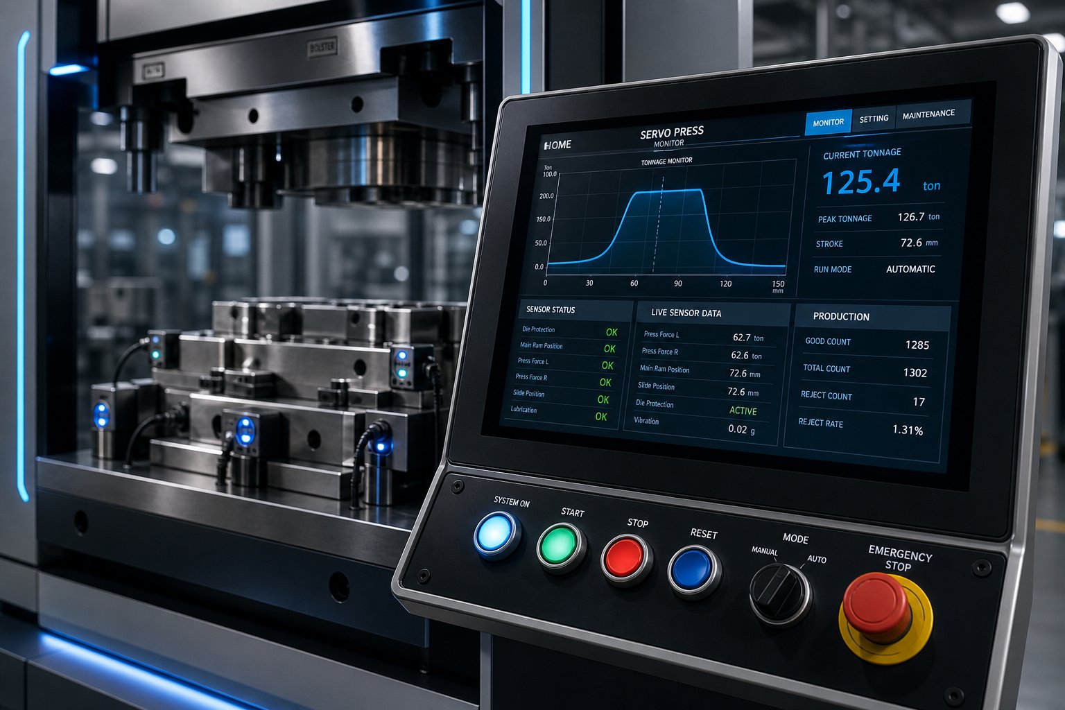
Servo drives, embedded sensors, and cloud-connected analytics aren't future concepts - they're reshaping what industrial metal stamping looks like right now. The press that ran a fixed stroke profile for 30 years is giving way to machines that adapt in real time, and the die that relied on scheduled sharpening is being outfitted with sensors that announce wear before the first bad part ever reaches the inspection table. Understanding these capabilities matters whether you're evaluating capital equipment or choosing among stamping press suppliers for your next tooling program.
Servo Press Technology and Programmable Motion
A conventional mechanical press delivers one thing: a fixed motion curve dictated by crank geometry. The ram accelerates, hits bottom dead center, and returns - the same path, every stroke, regardless of what the material actually needs. Servo presses replace that constraint with fully programmable motion profiles controlled by high-torque servo motors.
What does that unlock in practice?
- Optimized forming speeds - The ram can slow through a difficult draw section and accelerate through open travel, reducing material stress without sacrificing overall cycle time. You shape the velocity curve around the part, not the other way around.
- Dwell at bottom dead center - Holding the ram momentarily at full extension lets material fully coin or set into a form. This eliminates springback on parts that would otherwise require secondary correction.
- Pendulum motion - For shallow blanking or piercing operations, the ram doesn't need a full 360-degree rotation. Servo press research from MetalForming Magazine shows that pendulum mode uses only a partial rotation per stroke, significantly reducing cycle time. The key is matching the feed angle precisely - too short and the strip can't advance properly, too long and you lose the speed advantage. The shorter the pendulum, the higher the production rate, but also less time for the material to feed or transfer.
- Load signature analysis - Because the servo motor tracks torque throughout every degree of rotation, operators can read the load signature to identify where force builds, where it drops, and whether negative tonnages stay within press limits. Peaks and valleys in that signature reveal tooling problems long before they cause scrap.
One practical rule of thumb from the same research: aim for a motion profile that achieves 90 percent or more of the programmed maximum production rate. If actual speed falls significantly below programmed speed due to misfeeds or part instability, the solution isn't to slow the press - it's to redesign the motion profile to address the root cause. That iterative optimization process is what separates a servo press running at full capability from one that's simply expensive.
For high speed progressive die stamping, servo technology means you can run complex forming operations at speeds previously reserved for simple blanking - provided the motion profile is engineered with the same rigor as the die itself. An automated metal stamping machine built on servo architecture offers the flexibility to handle mixed part numbers, advanced high-strength steels, and tight tolerances without dedicating a separate press to each challenge.
Sensor Integration and In-Die Monitoring
The servo press tells you what's happening at the ram. In-die sensors tell you what's happening at the part - where quality is actually made or lost. Sensor integration is moving from optional add-on to baseline expectation among metal stamping press manufacturers building equipment for demanding applications.
The sensor categories that matter most:
- In-die force sensors - Piezoelectric sensors embedded directly in the die structure measure forming forces at individual stations. A force spike at station four tells you something different than a spike at station nine. Station-level data pinpoints which operation is degrading, guiding maintenance to the exact insert that needs attention.
- Acoustic emission monitoring - High-frequency microphones detect the ultrasonic signatures of crack propagation in punches or die blocks. A punch developing a fatigue crack emits a distinct acoustic pattern several thousand strokes before it fractures completely. Catching that pattern prevents the cascade failure that occurs when a broken punch fragment damages adjacent stations.
- Vision systems at press speed - High-speed cameras inspect every part as it exits the die, checking dimensional features, edge quality, and surface defects at full production rate. Automated sensor monitoring can achieve missed-inspection rates below 0.05 percent with sub-second response times - a capability that manual sampling at 50 pieces per hour simply cannot match.
- IoT connectivity and predictive maintenance - Industry analysis from Digiforming details how IoT-connected sensors transmit real-time data to cloud platforms where machine learning algorithms learn normal operating patterns. Any deviation - a gradual pressure drop in gas springs, rising vibration in a bearing, or temperature drift in a motor - triggers a predictive alert. Maintenance teams intervene before failure occurs, eliminating the unplanned downtime that reactive strategies accept as inevitable.
The compounding benefit is significant. Sensor data from the press (tonnage monitors, brake monitors, vibration) combined with in-die data (station forces, acoustic emissions, part measurements) creates a complete digital picture of system health. Over time, that dataset reveals correlations invisible to human observation - like the relationship between ambient temperature shifts, material batch variation, and dimensional drift on a specific feature. Progressive die stampings suppliers who invest in this monitoring infrastructure deliver measurably higher uptime and tighter quality distributions than those relying on traditional methods.
Choosing a Partner for Advanced Die Stamping Solutions
Technology only delivers value when the team behind it can execute across the full process chain. A precision metal stamping machine manufacturer with a servo press in the catalog but no CAE capability upstream can't optimize motion profiles for your specific part. A die shop with beautiful CNC equipment but no in-house tryout press can't validate forming behavior before shipping tooling to your floor.
When evaluating progressive die stampings suppliers or stamping press suppliers for a custom die program, these criteria separate capable partners from those who'll leave gaps in execution:
- Feasibility and CAE simulation capability - Can the supplier run FEA-based forming simulations to validate material flow, predict thinning, and determine springback compensation before committing to steel? This front-end investment prevents the most expensive category of tooling rework. YICHEN integrates CAE simulation into every stamping die program from the feasibility stage, catching formability risks while changes are still digital and inexpensive.
- Precision machining capacity - Progressive die components demand wire EDM, sinker EDM, jig grinding, and CNC milling to micron-level tolerances. Ask whether the supplier machines critical components in-house or subcontracts - subcontracting introduces handoff delays and accountability gaps. YICHEN maintains in-house precision machining for die components, keeping tolerances and lead times under direct control.
- Trial-run protocols and press capacity - Does the supplier own tryout presses that match your production press specifications? Can they run structured tryout sequences with CMM verification, or do they ship untested tooling? YICHEN conducts full trial runs on in-house presses, delivering CMM-verified dimensional data with the die - not after it arrives at your plant.
- Quality inspection infrastructure - CMM equipment, optical measurement, and SPC-based qualification processes confirm that the die produces within tolerance consistently. An iso 9001 certified metal stamper brings documented quality management systems that provide traceability from raw material through final die qualification.
- End-to-end accountability - The most common failure mode in tooling programs isn't a single technical error - it's the gap between stages where one vendor's responsibility ends and another's begins. A supplier managing feasibility, die engineering, precision machining, trial runs, and inspection as a connected workflow eliminates those gaps entirely.
For sourcing managers and engineers moving from research toward an RFQ, the evaluation framework above applies regardless of part complexity or production volume. The difference between a tooling program that launches on schedule and one that spirals through revision cycles usually traces back to how well the supplier connects these stages into a single accountable process.
Whether you're specifying a servo press for a new production line or sourcing progressive die tooling for an existing machine, the direction is clear: smarter presses, sensor-rich dies, and suppliers who bridge the full engineering chain from simulation to qualified production. The die stamping machine of five years from now will generate more data, adapt more dynamically, and demand more integrated partnerships than at any point in the technology's history. Position yourself on that side of the curve, and the system performs. Ignore it, and the system falls behind - quietly, incrementally, and expensively.
Frequently Asked Questions About Die Stamping Machines
1. What is the difference between a die stamping machine and a stamping press?
A stamping press refers only to the force-generating frame and drive system, while a die stamping machine is the complete integrated system that pairs the press frame with a purpose-built die set. The die is not an accessory - it is half the system. Performance, part quality, and production efficiency all depend on how well both halves work together, including matched tonnage capacity, shut height alignment, and synchronized feed timing.
2. How do you calculate the tonnage needed for a die stamping machine?
Tonnage for cutting operations equals the cut perimeter multiplied by material thickness multiplied by the material's shear strength. For progressive dies, you must sum the tonnage from every station - piercing, forming, stripping, and cutoff - since the press hits all stations simultaneously. Engineers typically add a 20-30% safety margin to account for material variation and tooling wear. Forming and drawing operations use different calculations based on tensile strength rather than shear strength.
3. What types of dies are used in die stamping machines?
Four main die configurations exist, ranging from simple to complex: single-station dies perform one operation per stroke (blanking, piercing, or forming); compound dies execute multiple cutting operations simultaneously for tight positional accuracy; progressive dies advance coil strip through sequential stations to produce finished parts at high speed; and transfer dies move individual blanks between independent stations for larger or more complex geometries that cannot be produced on a continuous strip.
4. How often should a die stamping machine be maintained?
Press maintenance follows a tiered schedule: slide gib lubrication every shift, clutch-brake oil lubrication daily, drive belt inspection weekly, and full parallelism and electrical checks annually. Die maintenance is condition-based - monitor burr height every 50,000 strokes and sharpen cutting edges when burrs exceed threshold limits. Guide pin clearance should be checked every 100,000 strokes. Neglecting either press or die maintenance causes compounding wear that shortens both the machine and tooling lifespan significantly.
5. What should I look for when choosing a die stamping supplier?
Evaluate five core capabilities: CAE simulation for validating formability before cutting steel, in-house precision machining (wire EDM, CNC milling, jig grinding) for maintaining tolerance control, tryout presses that match your production press specs, CMM-based inspection infrastructure for statistical qualification, and end-to-end project accountability from feasibility through production release. Suppliers like YICHEN who manage the entire chain - from simulation through machining, trial runs, and inspection - eliminate the handoff gaps where quality problems typically hide.


