


What a Progressive Die Stamping Press Actually Does
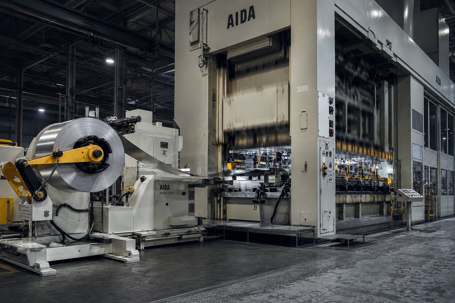
When you hear "progressive die stamping press," it's tempting to picture a single machine slamming metal into shape. The reality is more nuanced. This isn't just a press. It's an integrated system: a stamping press, a precision-engineered progressive die, a coil feed line, and a controls package all working in lockstep to convert flat metal strip into finished parts at production speed.
Definition of a Progressive Die Stamping Press
So what is a progressive die, and how does it relate to the press it sits inside? A progressive die is a specialized multi-station tool installed in a stamping press. A metal coil strip feeds into the die and advances through a sequence of stations with each press stroke. Every station performs a specific operation, whether that's blanking, piercing, bending, forming, or coining. By the time the strip reaches the final station, a completed part separates from the carrier strip and drops out ready for use.
A progressive die stamping press is an integrated production system combining a precision stamping press, a multi-station progressive die, a servo-driven coil feed, and synchronized controls to transform flat metal strip into finished parts in a single continuous operation.
Unlike a generic stamping press that might run single-hit dies or compound tools, a press built for progressive die stamping demands three things that set it apart: precise slide motion repeatability stroke after stroke, consistent shut height control so every station engages the strip at the correct depth, and exact feed synchronization so the strip advances by the correct pitch before each stroke fires. Remove any one of those elements, and tolerances drift, dies crash, or parts come out wrong.
How the Press, Die, and Feed Work Together
Imagine you're watching the system run. Here's how does a stamping press work in a progressive setup:
- The coil unwinds from a decoiler, passes through a straightener to remove coil set, and enters a servo roll feeder.
- The feeder advances the strip by a fixed distance, called the feed pitch, timed precisely to the press stroke cycle.
- Pilot pins in the die engage pre-pierced holes in the strip, correcting any minor feed error and locking the strip's position before the working stations engage.
- The press ram descends, and every station performs its operation simultaneously on different sections of the strip.
- The ram retracts, lifters raise the strip clear of lower die details, and the feeder advances the strip one more pitch for the next stroke.
Each component depends on the others. The press provides the force and motion profile. The die defines what happens to the metal at each station. The feed system controls progression accuracy. And the controls package ties them together, monitoring tonnage, verifying feed position, and stopping the press instantly if a sensor detects a misfeed or strip buckle. Progressive die stamping succeeds because these elements operate as one unit, not as separate machines bolted together on an afterthought.
This system-level perspective matters because sizing or specifying any single component in isolation leads to mismatches. A die designed without understanding the press's deflection characteristics will wear unevenly. A feed system chosen without considering strip width and material stiffness will introduce positional errors. The press frame type, drive mechanism, and tonnage rating all flow directly from what the die and material demand, which is exactly where press selection starts to get interesting.
Press Frame Types and Drive Mechanisms Compared
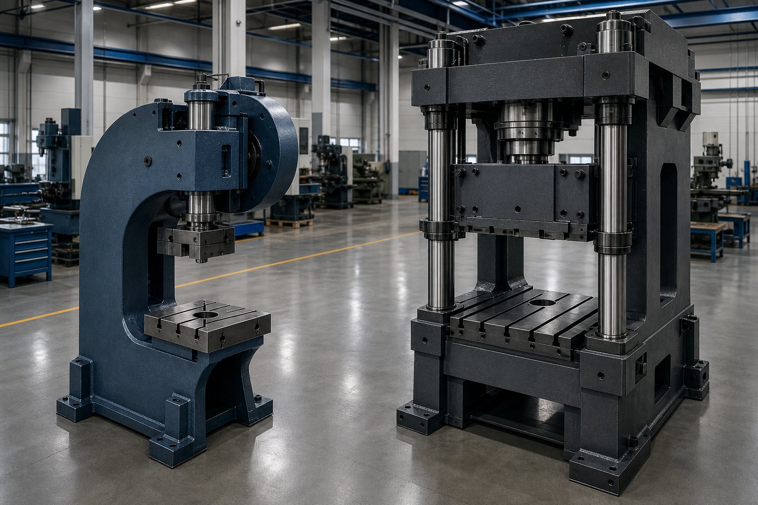
The frame holding your progressive die determines how much deflection you'll fight, how fast you can run, and how long your tooling lasts. Pick the wrong frame type or drive system, and you'll chase tolerance issues for the life of that die. Two frame architectures dominate the progressive stamping press landscape, and three drive mechanisms compete for the work inside them.
C-Frame vs. Straight-Side Press Frames
A C-frame (or gap-frame) press provides open access on three sides of the die area, making it compact and cost-effective for lighter progressive work. You'll typically find these in the 35 to 250 ton range running smaller progressive dies with fewer stations. The tradeoff? That open "C" structure deflects angularly under load, meaning the slide can tilt slightly as tonnage increases. For simple piercing and blanking progressives, this is manageable. For tight-tolerance forming across a wide die, it becomes a problem.
Straight-side presses eliminate that angular deflection with vertical columns supporting the crown on both sides. The geometry locks the slide path, keeping it parallel to the bolster regardless of where the load concentrates. For progressive die press applications demanding consistent part quality across 10, 20, or even 30+ stations, that rigidity is non-negotiable.
The structural difference shows up most clearly in how each frame handles off-center loading. Progressive dies rarely distribute force evenly. Forming stations hit harder than piercing stations, and they're often clustered toward the back of the die. A straight-side frame with wide connection spacing places much of the load between connection points, reducing cantilevered forces that try to tilt the slide.
| Criteria | C-Frame (Gap Frame) | Straight-Side |
|---|---|---|
| Tonnage Range | 35 - 250 tons typical | 150 - 3,000+ tons |
| Deflection Behavior | Angular deflection under load; open frame flexes | Minimal deflection; vertical columns resist tipping |
| Bed Size | Smaller; limits die length | Larger bed and bolster dimensions available |
| Progressive Die Applications | Small parts, fewer stations, lighter-gauge materials | Multi-station dies, tight tolerances, heavy forming |
| Speed Capability | Up to 600+ SPM for high-speed variants | Up to 300+ SPM standard; high-speed variants higher |
| Suspension Points | Single-point | 2-point or 4-point |
| Off-Center Load Resistance | Limited | Superior, especially 4-point designs |
When a progressive stamping machine requires a bed length exceeding 1.5 meters left-to-right, manufacturers typically move to a two-point connection design. Once the die also extends beyond 2 meters front-to-back, a four-point press becomes the practical choice. Those four suspension points distribute the forming load more evenly and resist the torsional forces that multi-station progressive dies generate across their working envelope.
Mechanical, Servo, and Hydraulic Drive Systems
The drive mechanism determines how the slide moves through its stroke, and that motion profile has direct consequences for what your progressive die can accomplish at speed.
Conventional mechanical drives use an electric motor spinning a flywheel, which transfers energy through a clutch to a crankshaft or eccentric gear system. The slide follows a fixed sinusoidal motion: it accelerates through mid-stroke and slows near bottom dead center. This is proven, reliable technology for progressive work. A die stamping machine with a direct-drive mechanical system offers the highest speeds and lowest energy loss, while geared variants provide greater torque for deeper forming operations. High-speed mechanical presses can exceed 1,000 strokes per minute for small-pitch progressive work.
A specialized variant worth noting is the link motion press, which uses a toggle-link mechanism to modify the slide velocity curve. Instead of the symmetrical motion of a standard crank, the link motion press produces a slower approach speed near bottom dead center while maintaining fast return speed. This gives more dwell time for forming without sacrificing overall cycle rate, making it popular for progressive dies that combine piercing with moderate drawing operations.
Hydraulic drives deliver full tonnage at any point in the stroke, not just near the bottom. For progressive dies that include deep-draw stations requiring force early and consistently through a long working window, hydraulic presses fill a niche. The limitation? Cycle speed. Hydraulic systems are significantly slower than mechanical alternatives, so they're reserved for progressive applications where draw depth outweighs speed requirements.
Why Servo Presses Change What Progressive Dies Can Achieve
Servo-mechanical presses represent the most significant evolution in progressive die press technology in decades. They replace the flywheel-clutch-brake assembly with high-torque servo motors driving the crankshaft directly. The result: fully programmable slide motion within every stroke.
What does that mean in practice? Consider a progressive die with both delicate piercing stations and aggressive forming stations. On a conventional mechanical press, every station sees the same velocity curve. A servo press lets you program the slide to move fast during approach, slow down through the forming zone for better material flow and reduced springback, then accelerate again on the return stroke. Production output can double when running progressive dies with half-motion profiles that eliminate unnecessary slide travel.
Servo technology also enables motion profiles that were simply impossible before:
- Half motion reduces stroke length for shallow progressive work, dramatically increasing SPM.
- Free motion (coining) strikes the material multiple times at bottom dead center within a single cycle, reducing or eliminating springback without adding die stations.
- Vibration motion supports deep drawing within progressive dies, potentially reducing the number of forming stations needed.
Dynamic balancing becomes critical at high speeds regardless of drive type. As stroke rates climb, the reciprocating mass of the slide generates vibration that can affect feed accuracy and accelerate wear. High-speed progressive stamping machines incorporate counterbalance systems, either mechanical or pneumatic, that offset these inertial forces and allow the press to maintain precision at elevated SPM.
The choice between frame type and drive system isn't made in isolation. It flows directly from what the die demands: how many stations, how complex the forming, what tolerances the finished part requires, and what production volumes justify the investment. Those die requirements, in turn, trace back to the material being stamped and the forces each station must generate.
Progressive Die Design Fundamentals That Drive Press Requirements
Every decision made on a progressive stamping die design drawing translates directly into a press specification. More stations mean a longer bed. Complex forming stations mean more tonnage. Tighter pilots mean a more precise feed system. The die doesn't exist independently of the press that runs it. It dictates what that press must deliver.
Station Layout Sequencing and Operation Order
When engineers lay out a progressive stamping die, the sequence of operations follows a logic rooted in material behavior. You generally pierce and notch first while the strip is still flat and stable. Forming and bending come later, after surrounding material has been trimmed away to allow metal flow. The final station separates the finished part from the carrier strip.
Here's the typical station sequence for a representative prog die:
- Punch pilot holes and internal features (piercing, notching)
- Cut relief slots and outline sections to free material for later forming
- Perform bending, drawing, or embossing operations
- Add coining or shaping for dimensional accuracy
- Cut off or separate the finished part from the carrier strip
This isn't arbitrary. Piercing before forming prevents hole distortion. Talan Products notes that sometimes piercing must occur after forming when tolerance demands on specific features make post-form punching the only way to hold position. Empty stations may also appear between complex operations to provide structural strength for die inserts or to allow space for special mechanisms.
Why does station count matter for press selection? Each station adds length to the die. A 12-station progressive die tooling setup needs a bolster and bed that accommodate that footprint with room to spare. Every active station also contributes to the cumulative tonnage load. More stations hitting simultaneously at bottom dead center means the press must handle the sum of all those peak forces without deflecting beyond acceptable limits.
Strip Layout and Carrier Strip Design
Strip layout is the foundation of progressive stamping die design. It determines part orientation on the material, pitch distance between stations, material utilization, and the carrier configuration that holds everything together during feeding.
Two key dimensions define the strip: width and pitch. Strip width encompasses the part blank, carrier material on one or both edges, and any scrap bridges between adjacent parts. Pitch is the distance the strip advances per stroke, and it directly sets the feed length your servo roll feeder must deliver with each cycle.
Carrier strip design varies based on part geometry and forming requirements:
- Edge carriers (single or bilateral) run along one or both sides of the strip. A bilateral carrier offers superior stability and positional accuracy, especially for thin materials below 0.2 mm. Single-edge carriers suit parts with bending on one end.
- Center carriers run through the middle of the strip, connecting parts on both sides. These work well for symmetrical bending parts and reduce scrap compared to edge carriers.
- Stretch web carriers incorporate flexible tabs that allow individual parts to move vertically through forming and drawing stations without disturbing adjacent progressions.
A solid carrier works for basic cutting and bending where the strip stays flat throughout. But when progressive stamping dies involve deep forming or drawing at multiple stations, the carrier must flex without breaking or pulling adjacent parts out of position. A poorly designed carrier can cause total tool failure, so engineers often validate designs through simulation software or manual wax-cutting techniques before committing to tool steel.
Material utilization is a constant pressure in strip layout planning. Tilting parts, nesting blanks, or choosing narrower carriers can push utilization from 65% toward 75% or higher. But every percentage point gained must be weighed against strip stability during feeding and the manufacturability of the resulting prog die.
Pilot Placement for Positional Accuracy
Pilots are what keep progressive dies producing accurate parts over millions of cycles. Without them, minor feed errors accumulate from station to station, and positional drift destroys tolerances.
The standard approach: punch pilot holes at the first station, then engage pilot pins starting at the second station. These pins enter the pre-pierced holes just before the working punches contact the strip, correcting any residual positioning error from the feed system. For longer progressive dies, pilots are typically placed every two to three stations to prevent cumulative error from building up across the strip length.
Pilot hole placement raises a practical question. Should you use the part's own holes as pilot references, or punch dedicated holes in the carrier? Using part holes saves material but risks elongating features that need tight tolerances. Dedicated pilot holes on the carrier scrap area preserve part integrity at the cost of slightly wider strip.
The precision of your pilot engagement ties back directly to feed system requirements. Tighter pilot-to-hole clearances demand that the feed system delivers the strip within a narrower positional window on every stroke. If your progressive dies need positional accuracy below +/-0.05 mm across 15 or more stations, the feed system and pilot strategy must be engineered as a matched pair, not specified independently.
Strip width, pitch distance, station count, and carrier type all cascade into press specifications. A wider strip needs a wider feed opening. A longer pitch at high speed demands faster feed acceleration. More stations need more bed length. And the forces generated across all those stations, hitting the strip simultaneously, determine whether a 200-ton or 400-ton press belongs under that die. Those force calculations deserve their own careful analysis.
How Material Properties Influence Press and Die Performance
Strip width, pitch, and station count tell you how big the press needs to be. But the material running through that die tells you how hard the press needs to hit, how fast it can cycle, and how many forming stations you'll need before the part comes out right. Choose a press based only on die geometry and you'll underestimate tonnage, accelerate tool wear, or produce parts that spring out of tolerance the moment they leave the die.
How Tensile Strength and Thickness Affect Tonnage
Every progressive metal stamping operation starts with a fundamental relationship: the force required to cut, form, or draw metal scales with both material thickness and its resistance to deformation. For blanking and piercing, the formula is straightforward: perimeter multiplied by thickness multiplied by shear strength. For drawing and forming, ultimate tensile strength replaces shear strength because the material is in tension rather than being sheared.
Consider what this means in practice. A 1.0 mm low-carbon steel strip with a shear strength around 25 tons/in² needs far less piercing force than a 1.0 mm stainless steel strip at 40+ tons/in². Run both through the same 12-station progressive die layout and the stainless version demands roughly 60% more press tonnage for the identical geometry. That difference compounds across every active station hitting simultaneously at bottom dead center.
Thickness amplifies the effect. Doubling material gauge from 0.5 mm to 1.0 mm doesn't just double the required force. It doubles the shear area for cutting operations and increases the bending moment for forming operations. High-strength steels in the 1.5 to 3.0 mm range can push tonnage requirements into territory where only straight-side presses with adequate energy reserves can handle the load without jamming at BDC.
This is why progressive stamping materials must be specified early in the design process. The material choice cascades into tonnage calculations, which cascade into press selection, which determines the capital investment for the entire production cell.
Work Hardening Across Multiple Forming Stations
Here's where progressive stamping gets tricky compared to single-station forming. When metal deforms plastically, it gets harder and less ductile. This is work hardening, and it happens at every forming station in a progressive die. The strip that enters station 8 isn't the same material that entered station 1. It's been pierced, bent, partially drawn, and each deformation has raised its yield strength while reducing its remaining formability.
Why does this matter for press and die design? Each successive forming station encounters stiffer material that requires more force to shape. Engineers must account for this cumulative hardening when calculating station-by-station tonnage. Underestimate it, and your final forming stations either crack the material or demand more force than the press can deliver at that point in the stroke.
Different alloys respond very differently to repeated deformation:
- Low-carbon steel work-hardens moderately and retains reasonable ductility across multiple forming hits, making it forgiving in carbon steel progressive stamping applications.
- Stainless steel (particularly austenitic grades like 304 and 316) work-hardens aggressively. Its yield strength can nearly double after significant cold work, and galling propensity increases as the surface hardens, requiring special coatings or in-process lubrication strategies.
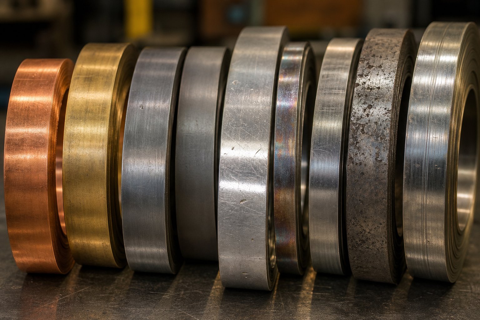
- Copper and brass work-harden at moderate rates but start with relatively low tensile strength, so they remain formable through more stations before reaching their limit.
- High-strength steels (HSLA, dual-phase) start with limited ductility and harden quickly, meaning engineers must distribute deformation carefully across more stations with less work per hit.
For challenging alloys, progressive dies sometimes incorporate intermediate stress-relief features or use staged redraws with minimal deformation per step to keep cumulative strain within safe limits. The alternative is cracking, which means scrap, downtime, and die repairs.
Springback Behavior and Station Compensation
Every bent or formed feature wants to spring back toward its original flat shape when the press ram retracts. The degree of springback varies dramatically between materials, and it directly determines how forming stations must be designed.
Low-carbon steel springs back modestly, perhaps 1 to 3 degrees on a typical bend. You can compensate by overbending slightly, and the part relaxes into spec. Aluminum alloys spring back more, typically 3 to 5 degrees, because of their lower elastic modulus relative to yield strength. High-strength steels are the worst offenders, with springback angles reaching 5 to 10 degrees or more depending on the bend radius and material grade.
In a progressive die, springback compensation happens at the tooling level. Engineers design forming punches and die cavities with calculated overbend angles so the part relaxes into the target geometry. Simulation-driven approaches, as described in springback best practices from FormingWorld, use predictive modeling to determine the exact compensation needed before any tool steel gets cut. Getting this wrong means parts drift out of tolerance, and the fix often requires recutting die inserts.
Progressive stamping aluminum presents a unique challenge beyond springback alone. Aluminum's tendency toward galling means die surfaces must be polished to mirror finishes, lubrication must be carefully controlled, and press speeds often need to be reduced to prevent surface scoring. The combination of high springback, low formability limits, and galling sensitivity means aluminum progressive dies typically require more stations to achieve the same geometry that steel could produce in fewer hits.
| Material Family | Typical Thickness Range | Relative Tonnage Requirement | Formability Rating | Key Press and Die Considerations |
|---|---|---|---|---|
| Low-Carbon Steel (1008, 1010) | 0.3 - 3.0 mm | Baseline (1x) | High | Moderate springback; standard die clearances; most forgiving for multi-station forming |
| Stainless Steel (304, 316L) | 0.2 - 2.5 mm | 1.5x - 1.8x | Moderate | Aggressive work hardening; galling requires coated tooling; higher tonnage per station |
| Aluminum Alloys (5052, 6061) | 0.3 - 3.0 mm | 0.5x - 0.7x | Low to Moderate | High springback; galling risk; reduced speed; polished die surfaces required |
| Copper and Brass (C110, C260) | 0.1 - 2.0 mm | 0.6x - 0.8x | High | Low tensile strength; burr-prone; requires sharp tooling and specialized lubricants |
| High-Strength Steel (HSLA, DP600) | 0.5 - 3.0 mm | 2.0x - 3.0x | Low | Extreme tonnage; rapid tool wear; limited forming per station; requires robust press frame |
The table makes one thing clear: material selection isn't just a design decision. It's a press sizing decision, a tool life decision, and a production speed decision all wrapped into one. A progressive die stamping press rated comfortably for carbon steel may be dangerously undersized for the same part geometry in stainless or high-strength steel. And an aluminum version of that same part, while requiring less force, might need more stations and slower cycle rates to avoid surface defects and hold dimensions.
These material behaviors feed directly into how you calculate total press tonnage. Each station's force requirement depends not just on geometry but on how that specific alloy responds to cutting, bending, and forming at that point in its work-hardening journey through the die.
Tonnage Calculation and Press Sizing for Progressive Dies
Material properties tell you how hard each station hits. But knowing individual forces isn't enough. You need to sum them, account for everything happening simultaneously across the die, and then match that total against the right press specification. Get this calculation wrong by even 15 to 20 percent and you'll either jam a press at bottom dead center or wear it out years ahead of schedule. This is where progressive die metal stamping moves from engineering concept to capital investment decision.
Station-by-Station Force Calculation Method
The process starts at the strip layout. Every station that does work on the material generates a measurable force, and you need to calculate each one individually before combining them. Here's how the math works for each operation type:
Blanking and piercing: These are shearing operations. The formula is straightforward:
Required Tonnage = Perimeter (in.) x Material Thickness (in.) x Shear Strength (tons/in²)
Imagine you're piercing a 0.5-inch-diameter hole in 0.060-inch mild steel with a shear strength of 25 tons/in². The perimeter is 1.57 inches, so the piercing force equals 1.57 x 0.060 x 25 = 2.36 tons for that single punch. A station with six holes? Multiply accordingly. A progressive stamping die with 10 piercing stations each carrying similar loads adds up fast.
Bending and forming: Force calculations for bending depend on bend length, material thickness, die opening width, and the material's tensile strength. V-bending, wiping, and air bending each follow different formulas, but they all scale with thickness squared and material strength. More complex geometries like embossing or ribbing require empirical data or simulation-based estimates.
Drawing: For draw stations, ultimate tensile strength replaces shear strength in the calculation because the shell walls are in tension. The formula becomes: Perimeter x Thickness x Ultimate Tensile Strength. Draw reduction ratio and blank holder pressure add to the total. A shallow cup draw at 30% reduction behaves differently than a deep draw at 45% reduction, both in force magnitude and in where that force applies within the stroke.
Beyond the primary forming operations, you need to capture forces that are easy to overlook:
- Spring stripper pressure (the force holding the strip flat against the die face)
- Strip lifter pin forces
- Nitrogen pressure pad forces in forming stations
- Cam-driven side actions
- Scrap cutter loads at carrier cutoff stations
- Blank holder pads in draw stations
As stamping expert Dennis Cattell notes, you must record the load for every single station, including the skeleton scrap, web carrier, pilot hole punching, and final web scrap cutting. Miss any of these and your total underestimates reality. For complex stamping dies with 15 or more progressions, a color-coded strip layout helps ensure nothing slips through the cracks.
Summing Simultaneous Peak Loads
Here's the critical point that trips up less experienced engineers: not every station hits its peak force at the same moment in the press stroke. Piercing stations peak early in the cut, the moment the punch breaks through. Forming stations peak at different points depending on geometry. Draw stations build force progressively and may peak well before bottom dead center.
The conservative approach, and the safe one, sums the peak forces from all stations as though they occur simultaneously. In practice, staggering punch lengths by shearing on the cutting punches can spread the load over a few degrees of crank rotation, reducing the instantaneous peak. But for press sizing purposes, you calculate the worst case: every station at maximum load at the same instant.
Once you have that sum, apply a safety margin. General engineering practice typically adds 20 to 30 percent above the calculated total. This margin accounts for several real-world variables:
- Tool wear increasing cutting forces over time (dull punches need more force than sharp ones)
- Material property variation from coil to coil
- Temperature effects on material strength during high-speed operation
- Unaccounted secondary forces from strip handling and guidance
A stamping die designed for 85 tons of calculated peak load should run in a press rated for at least 105 to 110 tons. The goal is to operate at roughly 60 to 75 percent of press capacity during normal production. Running consistently above 80 percent capacity accelerates bearing wear, frame fatigue, and gibbing deterioration while reducing the window available for process variation.
Matching Press Specifications to Die Requirements
Tonnage is the headline number, but it's far from the only specification that determines whether a press suits your die. Here's what catches people off guard: a press might have the right tonnage rating but still be wrong for the job because of stroke position, energy limits, or dimensional mismatch.
Tonnage rating vs. stroke position. A mechanical press delivers its rated tonnage at a specific distance above bottom dead center (BDC). Non-geared presses under 45 tons typically rate at 1/32 inch from BDC. Larger geared presses deliver full capacity at 1/16 to 3/16 inch from BDC. If your die stamping operation demands peak force at a point higher in the stroke than where the press is rated, you may not have the tonnage you think you have. Draw operations that require sustained force over a longer working window are particularly susceptible to this mismatch.
Energy vs. tonnage. This distinction trips up even experienced teams. You can have a press with adequate tonnage but insufficient energy, which is a common cause of press jams at BDC. Energy is stored in the flywheel and released during the working portion of the stroke. If the work required exceeds the flywheel's available energy at a given speed, the motor can't restore enough energy between strokes and the press stalls. Calculating energy requirements (force multiplied by working distance at each station) is the essential second step after tonnage calculation.
Beyond tonnage and energy, engineers must evaluate a full set of dimensional and performance parameters to confirm compatibility between press and die:
- Shut height: The distance from the bolster surface to the slide face at BDC, with adjustment at maximum up position. Must accommodate total die stack height (lower die + upper die + any backing plates).
- Slide adjustment range: Allows fine-tuning of shut height to dial in part dimensions. Typically 3 to 6 inches on medium presses. Insufficient adjustment limits die setup flexibility.
- Stroke length: Must exceed maximum part depth plus clearance for strip lifting and feeding. A part with 25 mm draw depth might need 75+ mm stroke to clear lifters and allow feed progression.
- Bed and bolster dimensions: Must accommodate the die footprint with clearance for clamps, scrap chutes, and feed guides. Standard practice requires the die to load within two-thirds of the bed area for proper deflection distribution.
- Bolster hole pattern: T-slot or tapped hole locations must align with die clamping requirements.
- Strokes per minute (SPM): Must meet production volume targets based on annual demand and available run time. A die producing 1,000 parts per hour at 60 SPM may need a press capable of 100+ SPM to accommodate feed time and provide margin for downtime.
- Feed window (available degrees): The portion of crank rotation during which the strip can advance. Longer feed lengths at higher speeds need a wider feed window, which directly limits achievable SPM.
- Slide parallelism and repeatability: For progressive die stampings requiring tolerances below +/-0.05 mm, the press must maintain parallelism within micrometers under load, stroke after stroke.
One point worth emphasizing: oversizing press tonnage is always better than undersizing. An undersized press running near capacity creates a cascade of problems. Bearings wear faster. Frame deflection increases, changing die clearances and accelerating punch wear. Energy limitations cause speed restrictions that kill productivity. Die life drops because the entire system operates under stress it wasn't designed to sustain.
A press running at 60 percent capacity, by contrast, deflects less, generates less heat, maintains tighter slide parallelism, and gives you headroom for material variation or future die modifications that add stations. The capital cost difference between a 150-ton and 200-ton press is modest compared to the cumulative cost of premature die regrinding, unplanned downtime, and shortened press lifespan that come from operating at the ragged edge of capacity.
The takeaway? Calculate conservatively, add margin generously, and verify both tonnage and energy requirements against the press rating curve at the actual working height your die demands. These calculations set the floor for your investment, but they don't yet account for how fast you can actually run the system. Production speed introduces its own constraints that interact with everything above.
Stroke Rate vs. Part Complexity Tradeoffs
You've sized the press correctly for tonnage and energy. The die fits the bolster. The material is specified. Everything checks out on paper. But here's the question that determines your per-part cost for the life of that tool: how fast can you actually run it? The progressive die stamping process is ultimately governed by the slowest link in the cycle, and that link changes depending on part geometry, strip behavior, and how intelligently your motion profile is configured.
What Determines Maximum Stroke Rate
Strokes per minute isn't a single number you look up on a spec sheet and run forever. It's the result of several competing physical constraints, and the tightest one sets the ceiling for your entire line. Here's what limits achievable speed in high speed progressive die stamping:
- Feed length per stroke. The strip must advance the full pitch distance, decelerate, and settle into position before the slide reaches the work zone. Longer pitch means more linear travel per cycle, which either requires faster feed acceleration or fewer strokes per minute. To convert feed equipment speed into SPM, divide the equipment's linear capability (in inches per second) by the progression distance.
- Part lift height. After each stroke, lifters raise the strip clear of lower die details so it can advance freely. Deeper forms or taller die features require higher lift, which consumes more degrees of crank rotation for the strip to clear and resettle. Reducing lift height by distributing forming across more stations is one of the most effective ways to increase speed capability.
- Carrier strip strength. At high speeds, the strip experiences significant inertial loads during acceleration and deceleration. A weak carrier can buckle, stretch, or collapse, causing misfeeds. Parts with limited connection area between progressions may need carrier redesign to support the dynamic forces of high-speed feeding.
- Material deformation rate sensitivity. Some alloys behave differently when formed at high velocity. Strain-rate effects can increase forming forces or change fracture behavior, limiting how fast forming stations can operate without cracking the material.
- In-die sensor response time. Misfeed detectors, part-out sensors, and tonnage monitors all need time to read and signal the press control. If the sensor response time exceeds the available window between strokes, you must either slow down or accept the risk of running unprotected.
The relationship is clear: simpler parts with short progression, shallow features, and robust carriers can run at very high SPM. Complex geometries with deep forms, long feed lengths, and delicate carriers force the rate down. A small electrical connector might run at 800 to 1,200 SPM on a high-speed mechanical press, while an automotive bracket with multiple bends and a 75 mm pitch might top out at 60 to 80 SPM on the same tonnage frame.
Servo Press Speed Profiling for Complex Parts
Conventional mechanical presses offer one motion curve: the sinusoidal path dictated by crank geometry. Every portion of the stroke moves at a speed determined by crank angle, and you can't slow down through forming without slowing the entire cycle. Servo presses break that constraint entirely.
With programmable slide motion, you can run the approach and return portions of the stroke at maximum velocity while decelerating through the forming zone where material flow needs time. This means a progressive stamping process that would max out at 40 SPM on a mechanical press (because the forming stations need dwell time) might achieve 60 or 70 SPM on a servo press. The forming speed stays within material limits while the non-working portions of the stroke run as fast as the drive allows.
Servo technology offers specific motion modes that unlock speed gains for different scenarios:
- Pendulum mode uses a partial rotation rather than a full 360 degrees, eliminating wasted crank travel for shallow progressive work. As motion profile research shows, the shorter the pendulum the higher the production rate, but this also compresses the feed window, demanding faster feed equipment.
- Variable speed through stroke allows the slide to crawl at 10% of maximum speed through a critical draw station while running the return at full velocity, holding part quality without sacrificing overall cycle time.
- Multi-hit profiles deliver two or three controlled strikes at bottom dead center within a single press cycle, reducing springback without adding die stations or slowing the line.
One practical rule of thumb from servo press optimization: aim for an actual production rate at 90% or more of the programmed maximum. If you're running significantly below that threshold, the motion profile itself needs redesign rather than simply reducing press speed. Feed angle tuning, riser height reduction, and forming window minimization are all levers to pull before accepting a slower rate. Long run progressive stamping programs justify the time investment in profile optimization because even a 10% SPM gain compounds into significant cost savings over millions of cycles.
Die Changeover Optimization with SMED Principles
Speed during production only tells half the story. For shops running multiple part numbers through the same press, changeover time between dies directly erodes overall equipment effectiveness. A press producing 500 parts per minute means nothing if it sits idle for four hours between die changes.
This is where SMED (Single-Minute Exchange of Dies) principles transform progressive die economics. Despite the name, SMED targets changeover times under ten minutes rather than literally one minute. The methodology separates setup tasks into external activities (performed while the press is still running the previous job) and internal activities (only possible with the press stopped), then systematically converts internal tasks to external ones.
For progressive die stamping, practical SMED implementation includes:
- Standardized shut heights across die sets so the press adjustment doesn't change between jobs
- Quick-change bolster systems with rolling or hydraulic die carts that pre-stage the next die outside the press and slide it into position in under a minute
- Unified clamping systems using hydraulic or pneumatic clamps with standardized slot locations, eliminating manual bolt-up
- Pre-staged coil and feed setup so the new material is threaded and ready before the press stops
- Visual management and workplace organization ensuring every tool, shim, and connector has a designated location accessible without searching
The production impact is measurable. A shop converting from 2-hour changeovers to 10-minute changeovers gains roughly 110 minutes of productive run time per die change. Across three changes per shift, that's over five additional hours of parts production per day. For high-volume programs, this directly lowers per-part cost because the press spends more of its available hours making parts rather than waiting for setup.
SMED also enables smaller batch runs without penalty. Traditional long-changeover shops resist switching dies frequently, which leads to overproduction and excess inventory. Fast changeover makes it viable to run exactly what's needed, when it's needed, aligning progressive die production with lean manufacturing flow.
Speed optimization, whether through motion profiling or changeover reduction, ultimately depends on how well the press communicates with everything around it. The feed system must respond to speed commands with sub-millisecond precision. Sensors must detect problems within the available reaction window. And the entire cell must operate without constant human intervention to justify the investment in faster cycle rates.
Automation Integration and Modern Feed Systems
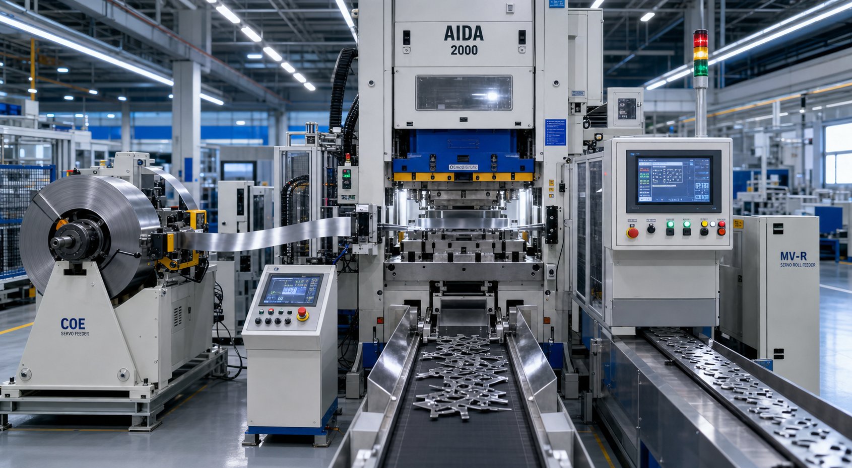
A progressive die stamping press running at 400 strokes per minute leaves roughly 150 milliseconds between hits. In that window, the strip must advance, settle into position, and every sensor must confirm the system is safe for the next stroke. No human can monitor that. The press needs to think for itself, and it does so through a layered automation architecture that transforms a standalone machine into a production cell capable of running lights-out.
Servo Feed Systems and Feed Accuracy
The stamping feed system is arguably the most critical peripheral on the line. Its job sounds simple: advance the strip by exactly the programmed pitch distance, every single stroke, regardless of speed variation or material behavior. In practice, achieving that repeatability at production rates demands precision engineering.
Three feed technologies serve progressive die applications:
- Servo roll feeds use servo-motor-driven rollers that clamp the strip and advance it a programmed distance. They offer the best accuracy (typically +/-0.025 mm or better), fastest acceleration, and widest adjustment range. Most modern progressive die lines use them.
- Air feeds use pneumatic cylinders to advance a gripper jaw assembly. They're simple, inexpensive, and suitable for shorter feed lengths at moderate speeds. Accuracy is lower than servo systems.
- Gripper feeds (mechanical) use cam-driven mechanisms for fixed progression distances. Fast and reliable for dedicated high-speed applications, but inflexible when changeover requires different feed lengths.
Feed accuracy isn't just about the mechanism itself. Feed-release timing plays a critical role. Where in the press stroke the feed rolls close determines whether extra material gets trapped between the die and feeder. If the roll closes at bottom dead center while stamping die lifters are still raising the strip, the additional material pulled through during that lift creates an overfeed condition. The result? Excessively long progressions, pilot damage, and scrap. Correct closure timing accounts for the feed-to-die distance, lifter travel height, and press speed to prevent this trap.
Roll pressure matters equally. Too little pressure causes slippage and short feeds, especially with thick materials that require more force to accelerate. Too much pressure bends the feed roll, inducing edge wave in wide coils or camber in narrow stock. Modern servo feed controllers compensate automatically when sensor data indicates strip wandering or thickness variation, adjusting progression length in real time without operator intervention.
In-Die Sensing and Die Protection
Running an automatic stamping cell without die protection is like driving at highway speed without brakes. Eventually, something goes wrong, and without sensors to stop the press within a fraction of one stroke, a single misfeed can destroy thousands of dollars in tooling punches, die inserts, and press components.
A comprehensive die protection system monitors multiple failure modes simultaneously:
- Misfeed detection: Sensors verify the strip has advanced to the correct position before the press fires. The detection window must account for your feeder's actual repeatability. As die protection experts note, if your feeder holds +/-0.005 inches but sensors are set to trigger at +/-0.003 inches, nuisance stops will plague your operation.
- Strip buckle detection: Continuous monitoring sensors verify the strip remains flat between the feeder and die entrance. A buckled strip entering the die means a double-thick hit that can crack punches or spring the press frame.
- Part-out detection: Photoelectric or proximity sensors confirm that each finished part has ejected from the die before the next stroke. A stuck part means a double hit, which is one of the fastest ways to destroy a die section.
- Tonnage monitoring: Load cells in the press connections track force signatures stroke by stroke. A sudden spike indicates a slug pull, broken punch, or misfeed. A gradual upward trend signals tool wear that needs attention before it becomes a failure.
- End-of-stock detection: Sensors detect when the coil is about to run out, stopping the press before the strip tail reaches active stations.
Modern resolver-based controllers are precise enough to monitor sensor signals within one-third of a degree of crankshaft rotation. This matters because some actuations, like an air-ejected part flying past a photoelectric sensor, last less than 10 milliseconds regardless of press speed. The best-practice approach connects die-mounted sensors through a single junction box and master cable rather than individual wires, eliminating connection errors during setup and preventing cable work-hardening failures from repeated coiling and uncoiling.
Scrap Removal and Unattended Operation
Every piercing station and cutoff operation generates scrap: slugs from holes, trim skeletons from blanking, and carrier webs from final separation. If any of that material doesn't exit the die reliably, it stacks up, interferes with the next stroke, and causes crashes. Slug management is what separates a die that runs unattended from one that needs an operator standing by with an air hose.
Scrap removal strategies include:
- Gravity drop: Slugs fall through die openings into chutes below the bolster. Works reliably when hole geometry and die clearance allow clean separation.
- Positive air blowoff: Timed air blasts eject parts or slugs that don't fall freely. Essential for upward-facing cavities or horizontal ejection paths.
- Vacuum systems: Pull slugs away from punch faces, preventing slug pulling (where a slug clings to the punch and re-enters the die on the next stroke). Particularly important for thin materials where surface tension holds slugs against tool surfaces.
- Mechanical ejectors: Spring-loaded or cam-driven pins positively push finished parts or scrap clear of the die on every stroke.
Beyond the die itself, a fully automated progressive die stamping cell integrates with plant-level systems for production visibility. Part counters track output against targets. SPC data collection captures critical dimensions at intervals for real-time process control. Tonnage signature data feeds predictive maintenance algorithms that flag tool wear before it produces scrap. And connectivity through OPC-UA or similar protocols lets production monitoring dashboards display press status, OEE metrics, and alarm history from anywhere on the plant network.
Here's the full component list for a modern automated cell:
- Servo-driven coil feed with automatic pitch compensation
- Coil straightener with powered pinch rolls
- Die protection controller with resolver-based timing
- Tonnage monitor with per-stroke signature analysis
- Misfeed, buckle, and part-out sensor array
- Automatic lubrication system (roller or spray)
- Scrap conveyor or vacuum collection system
- Part conveyor or bin-sorting system
- SPC gauging station (inline or sampling)
- Network-connected HMI with remote monitoring capability
When all these elements work together, the result is a cell that supports true lights-out operation, running through entire coils without human intervention, stopping only when sensors detect an anomaly or the coil runs out. The automation doesn't just increase throughput. It protects the tooling investment, maintains quality consistency, and generates the data needed to optimize the process continuously.
That level of integration raises a natural question. With all these capabilities available, how does progressive die stamping compare against other methods like transfer dies, compound tools, or multislide machines? The answer depends on your part geometry, volume requirements, and tolerance demands.
Progressive vs. Transfer vs. Compound Stamping Methods
Part geometry, annual volume, and tolerance specs don't just determine how you size a press. They determine whether a progressive die is even the right approach. Engineers who default to progressive tooling for every project leave money on the table when a transfer die, compound tool, or multislide machine would serve the application better. Conversely, choosing a simpler method for a part that genuinely needs progressive capability creates bottlenecks and quality headaches that compound over years of production.
Here's how the five major stamping methods stack up against each other, and when each one earns its place on the floor.
Progressive vs. Transfer Die Stamping
Both methods use multiple stations to build part features sequentially, but they differ fundamentally in how the workpiece moves between those stations. In a progressive die, the part stays connected to the carrier strip throughout the process, advancing with each press stroke until cutoff at the final station. In transfer die stamping, the part is separated from the strip early (or starts as a pre-cut blank) and is mechanically transferred between independent die stations using grippers, fingers, or robotic arms.
That distinction drives everything else. Progressive dies excel at small-to-medium parts where the geometry allows the workpiece to remain attached to a carrier. Think electrical connectors, brackets, clips, and terminals. The strip provides automatic indexing, eliminates part handling between stations, and enables very high speeds because nothing needs to grab and move a free part.
Transfer press tooling becomes necessary when parts are too large to feed from coil stock, require deep draws that exceed what carrier strips can support, or demand operations from multiple angles that would be impossible with the strip connected. Large automotive body panels, deep-drawn cups, and structural components typically route to transfer systems. The tradeoff? Slower cycle times and more complex material handling. Transfer die stamping typically runs at 15 to 40 strokes per minute compared to hundreds of SPM possible with progressive work.
From a cost perspective, transfer tooling can actually be less expensive per station because each die is independent rather than integrated into a single block. But the transfer press tooling requires additional investment in the mechanical transfer system itself, and per-part costs are higher at equivalent volumes due to slower speeds and increased handling.
Compound and Fine Blanking Alternatives
Not every part needs sequential stations. Compound die stamping performs multiple cutting operations in a single press stroke, producing a finished flat part in one hit. The die simultaneously blanks the outer profile and pierces internal holes, delivering parts with excellent flatness and concentricity because all features are cut in one motion relative to each other.
The limitation? Compound dies handle only flat geometry. No bending, no forming, no drawing. They're ideal for washers, flat terminal blanks, simple gaskets, and any part defined entirely by its cut profile. For these applications, compound die stamping delivers better flatness than progressive methods (because there's no strip advancement between operations) at lower tooling cost. But volumes must justify the dedicated die, and complexity caps out quickly.
Fourslide and multislide machines take a different approach entirely. Instead of vertical press force, they use four or more horizontal tool slides to bend, form, and cut wire or narrow strip from multiple directions simultaneously. The result is intricate three-dimensional parts, particularly springs, clips, and small brackets, produced at high speed with minimal tooling cost. Medical device progressive stamping handles precision contacts and EMI shields at volume, but for micro-formed clips and wire-based components under 50 mm, multislide machines often produce the same geometry faster and cheaper.
Fine blanking occupies a specialized niche. It uses a triple-action press with extremely tight punch-to-die clearances and a V-ring impingement plate that locks the material during cutting. The result is a smooth, fracture-free edge over the full material thickness, something conventional blanking can't achieve without secondary machining. Gears, sprockets, seatbelt components, and brake system parts commonly use fine blanking when edge quality and dimensional accuracy matter more than cycle speed.
Choosing the Right Stamping Method for Your Application
The decision framework boils down to five variables. Match your part against each one, and the right method usually becomes obvious:
- Part size and geometry: Small-to-medium parts with bends and forms suit progressive dies. Large or deeply drawn parts route to transfer. Flat-only profiles fit compound dies. Complex 3D wire or narrow-strip bends favor multislide.
- Production volume: Progressive stamping dominates above 50,000 parts annually where tooling amortization drives per-part cost down. Compound and multislide serve lower volumes cost-effectively. Fine blanking justifies its tooling expense at high volumes of precision components.
- Tolerance requirements: Fine blanking achieves +/-0.025 mm on cut features. Progressive dies hold +/-0.05 to +/-0.10 mm across formed features. Transfer tooling achieves similar tolerances but with larger part envelopes.
- Material type and thickness: Thicker stock (above 3 mm) and high-strength materials favor transfer systems due to higher tonnage requirements per station. Thin materials (0.1 to 1.0 mm) run efficiently in progressive or multislide setups.
- Budget and timeline: Progressive die tooling costs more upfront than compound or multislide tooling but delivers the lowest per-part cost at volume. Transfer tooling investment is comparable to progressive but carries additional press and automation costs.
| Method | Press Type | Ideal Volume Range | Part Size Range | Achievable Tolerances | Tooling Cost | Per-Part Cost at Volume |
|---|---|---|---|---|---|---|
| Progressive Die | Mechanical or servo, C-frame or straight-side | 50,000 - millions/year | Small to medium (up to ~300 mm) | +/-0.05 to +/-0.10 mm | High | Very low |
| Transfer Die | Straight-side mechanical or servo with transfer system | 10,000 - 500,000/year | Medium to large (up to 1,000+ mm) | +/-0.05 to +/-0.15 mm | High | Low to moderate |
| Compound Die | Mechanical, C-frame or straight-side | 5,000 - 500,000/year | Small to medium, flat only | +/-0.025 to +/-0.05 mm | Medium | Low |
| Fourslide / Multislide | Dedicated multislide machine | 10,000 - millions/year | Small (under 50 mm typical) | +/-0.05 to +/-0.10 mm | Low to medium | Very low |
| Fine Blanking | Triple-action hydraulic or mechanical fine-blank press | 25,000 - millions/year | Small to medium, flat or near-flat | +/-0.025 mm or better | Very high | Moderate |
In practice, the choice often maps to industry application patterns. Automotive components progressive stamping dominates production of high-volume brackets, connectors, terminal strips, and transmission components where annual quantities reach millions and per-part cost sensitivity is extreme. These parts are typically small enough to remain on a carrier strip, complex enough to need 8 to 20+ stations, and produced in volumes that amortize tooling costs within months.
Medical device progressive stamping serves a different profile: precision contacts, RF shields, connector pins, and implant sub-components where dimensional accuracy and surface finish matter as much as volume. These applications demand tight pilots, fine-pitch advancement, and often require clean-room-compatible processing, but the fundamental progressive approach remains ideal because the parts are small, geometrically complex, and needed in consistent high volumes.
Transfer methods claim the territory progressive dies can't reach: large structural stampings, deep-drawn housings, and parts requiring operations from multiple approach angles. Compound die stamping fills the gap for simpler flat parts where one-stroke production beats multi-station progression on both cost and quality.
The right method isn't always one or the other. Some production cells combine progressive dies for initial blanking and forming with transfer systems for secondary deep-draw operations. The decision framework above gives you the starting point, but the real answer comes from matching your specific part geometry, volume forecast, and quality requirements against the capabilities and economics of each approach. Once that choice is made, the question shifts from which method to which supplier can deliver the tooling and production capacity your program demands.
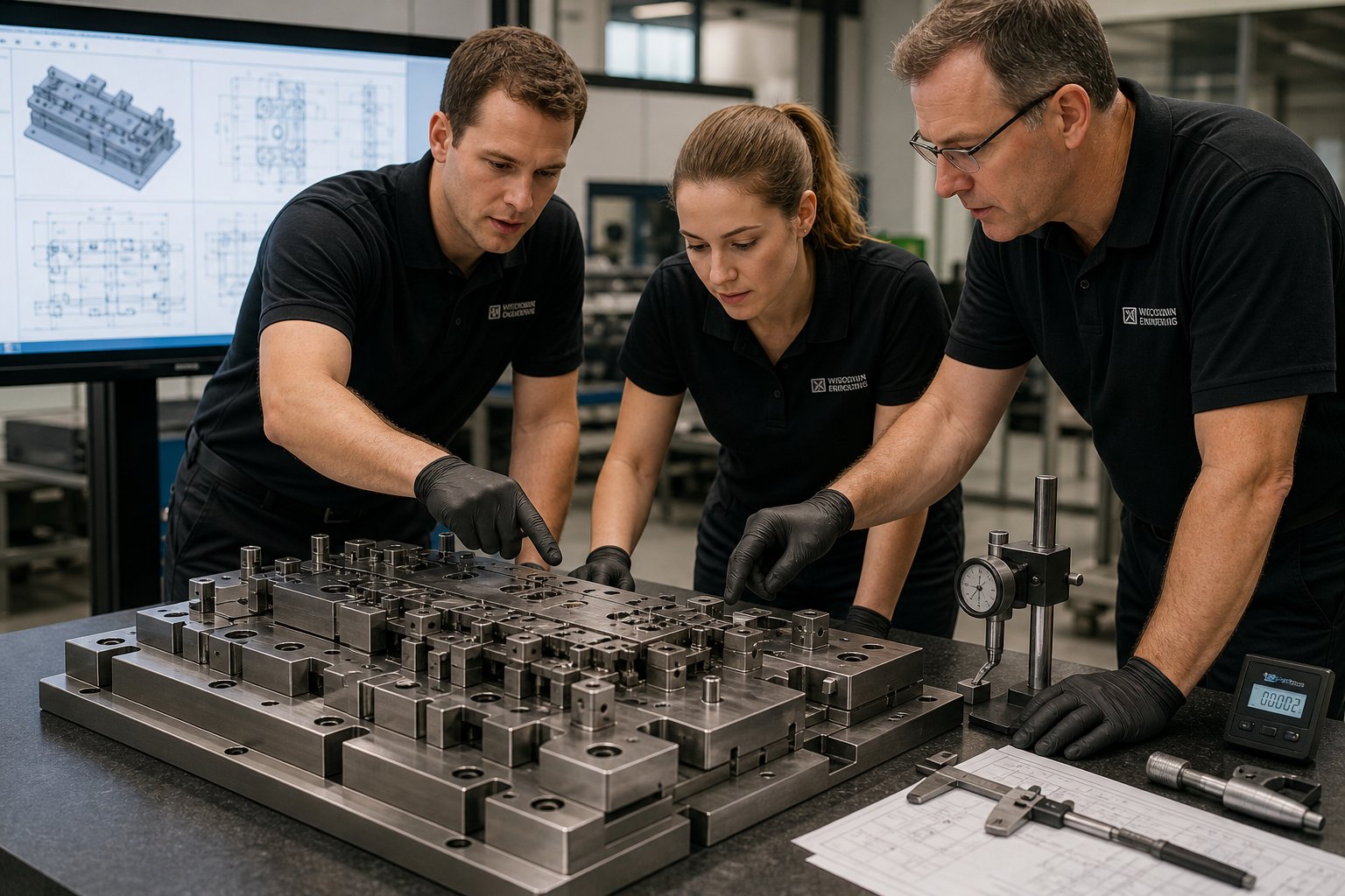
Sourcing Progressive Stamping Dies for Scalable Production
Selecting the right stamping method and press configuration is only half the equation. The other half? Deciding whether to bring that capability in-house or partner with a progressive stamping company that already has the engineering depth, production capacity, and quality infrastructure to deliver tooling that performs from day one. This decision shapes your cost structure, timeline flexibility, and operational risk for years.
When to Invest in a Press vs. Partner with a Die Supplier
Owning a progressive die stamping press makes sense under specific conditions: sustained annual volumes exceeding millions of parts across multiple programs, internal engineering expertise to maintain dies and optimize processes, and capital availability that doesn't strain cash flow for other growth initiatives. If you meet all three criteria, press ownership delivers maximum control over scheduling, quality, and per-part cost.
Most companies don't meet all three. And that's where the math gets interesting.
A comprehensive ROI analysis must account for more than the press purchase price. As BaySource Global's manufacturing decision framework outlines, the true cost of ownership includes capital equipment, property and maintenance costs, carrying cost of capital (including interest payments), inventory management overhead, staffing for operation and quality assurance, and technological expertise required to keep the system competitive. Contract manufacturing offers flexibility in scaling production up or down based on demand fluctuations without carrying those fixed costs during lean periods.
For teams producing fewer than 500,000 parts annually across limited part numbers, partnering with a progressive tool and die supplier typically delivers better economics. You avoid the capital outlay, eliminate the need for specialized press operators and die maintenance technicians, and gain access to engineering resources that would take years to build internally. The tradeoff is less scheduling control and dependency on your supplier's capacity and priorities.
Evaluating Progressive Die Suppliers for High-Volume Production
Choosing a progressive die manufacturer is among the most consequential sourcing decisions a production team makes. The quality, accuracy, and consistency of your tooling partner directly impacts part quality, total cost of ownership, and long-term competitiveness. A detailed evaluation framework from Eigen Engineering identifies eight key criteria that separate capable suppliers from risky ones.
Here's what your procurement team should assess:
- Engineering and design capability: Can the supplier develop custom progressive die designs from your part geometry, material specifications, and volume targets? Look for in-house CAD/CAM, FEA simulation for forming analysis, and strip layout optimization expertise.
- Material expertise: Does the supplier understand how different alloys behave across multiple forming stations? Work-hardening compensation, springback prediction, and galling prevention all require material-specific knowledge.
- Quality systems and metrology: Verify that the supplier uses CMM inspection, optical measurement, and SPC documentation to validate tolerances at each stage. Certifications like ISO 9001 establish a baseline, but inspection capability matters more than the certificate on the wall.
- In-house trial and validation facilities: A supplier with tryout presses can prove the die works before it ships to your floor. This eliminates weeks of debugging at your facility and confirms that production targets are achievable under realistic operating conditions.
- Production capacity and lead time reliability: Assess whether the supplier can meet your timeline without compromising quality. Past performance on delivery commitments tells you more than promises during the quoting phase.
- Die maintenance and after-sales support: Progressive dies wear. Punches dull, forming inserts fatigue, and clearances open up over millions of cycles. A supplier that offers ongoing maintenance support, spare component supply, and troubleshooting assistance protects your uptime.
- Scalability and flexibility: Your volumes will change. A progressive die manufacturers partner that can scale from pilot quantities to full mass production, and adapt tooling to engineering changes, provides far more long-term value than one with fixed capabilities.
- Technological proficiency: Evaluate CNC and wire EDM equipment quality, digital simulation tools, and willingness to adopt advanced manufacturing methods that improve die accuracy and reduce lead times.
For teams sourcing progressive stamping dies that require efficient multi-station forming, tight repeatability, and scalable mass production, suppliers like YICHEN focus specifically on helping production engineers and procurement teams bridge the gap between design intent and volume-ready tooling. Their progressive die stamping services emphasize the combination of engineering support and production scalability that high-volume programs demand.
Scaling from Prototype to Mass Production
The path from first-article samples to full-rate production isn't a single jump. It's a staged progression where each phase validates the next. Rushing to mass production tooling before the design is frozen, as the MakerStage scaling roadmap emphasizes, is one of the most expensive mistakes in hardware manufacturing. Mold revisions at production stage cost 30 to 50 percent of original tooling plus weeks of delay.
For progressive die stampings, the scaling sequence typically follows this pattern:
- Prototype validation (1-50 parts): CNC machined or wire-EDM samples confirm part geometry and fit. No die investment yet. This stage answers whether the design is correct before committing to tooling.
- Pilot tooling (50-5,000 parts): A simplified progressive die, sometimes with fewer stations or softer tool steel, produces parts for functional testing, assembly validation, and initial customer qualification. Design changes are still affordable at this stage.
- Production tooling (5,000+ parts): Fully hardened, production-intent progressive dies designed for the target press, material, and cycle rate. At this point the design must be frozen. Engineering changes mean recutting die inserts or rebuilding stations.
The critical trigger for moving between stages isn't just volume. It's design stability. A progressive die stampings supplier worth partnering with will push back if you try to order production tooling before tolerances are validated and the design has survived functional testing. That pushback protects your investment.
When evaluating progressive die manufacturers for long-term programs, ask specifically about their prototype-to-production workflow. Can they produce sample parts from soft tooling, validate dimensions against your print, iterate on station design based on tryout results, and then transition to hardened production dies without starting over? That continuity eliminates the translation errors that happen when prototype and production tooling come from different sources with different engineering interpretations.
The total cost of ownership for a progressive die program extends well beyond the initial tooling quote. Factor in die maintenance intervals, expected regrind frequency, spare punch and insert costs, estimated die life in total strokes, and the supplier's responsiveness when something needs attention at 2 AM on a Tuesday. A progressive stamping company that quotes 10 percent less upfront but can't support you when a forming insert cracks mid-run will cost you far more over the life of the program than a partner who prices for long-term reliability and backs it with responsive service.
Progressive Die Stamping Press FAQs
1. What is the difference between a progressive die and a transfer die?
A progressive die keeps the workpiece attached to a carrier strip throughout all stations, advancing it with each press stroke until final cutoff. A transfer die separates the part early and uses mechanical grippers or robotic arms to move it between independent stations. Progressive dies run faster (hundreds of SPM) and suit small-to-medium parts, while transfer dies handle larger parts, deep draws, and multi-angle operations at slower speeds (15-40 SPM). Progressive tooling costs more upfront but delivers lower per-part cost at high volumes due to speed advantages and eliminated part handling.
2. How do you calculate the tonnage needed for a progressive die stamping press?
Calculate the force for each station individually: blanking and piercing use perimeter multiplied by thickness multiplied by shear strength; bending uses material properties and geometry; drawing uses ultimate tensile strength. Then sum all peak forces assuming simultaneous engagement at bottom dead center. Add a 20-30% safety margin to account for tool wear, material variation, and temperature effects. Also verify that the press has sufficient energy (flywheel capacity) and that its tonnage rating applies at the actual working height your die demands. Best practice is to operate at 60-75% of press capacity for longevity.
3. What materials work best for progressive die stamping?
Low-carbon steel (1008, 1010) is the most forgiving material for progressive stamping due to moderate work hardening and predictable springback. Copper and brass offer high formability at lower tonnage requirements. Stainless steel works well but demands 1.5-1.8x more tonnage and requires coated tooling to prevent galling. Aluminum needs polished die surfaces, controlled lubrication, and often more forming stations due to high springback. High-strength steels (HSLA, dual-phase) require the most tonnage (2-3x baseline) and careful station distribution to avoid cracking from limited ductility.
4. Why are servo presses preferred for complex progressive die work?
Servo presses replace the fixed flywheel-clutch-brake assembly with programmable servo motors that allow variable slide speed within each stroke. This means you can slow through forming zones for better material flow and reduced springback while running fast on approach and return. Practical benefits include doubling output with half-motion profiles, eliminating springback with multi-hit profiles at BDC, and enabling deep drawing within progressive dies using vibration motion. Servo technology lets complex parts run at higher effective SPM without exceeding material forming limits, directly reducing per-part cost.
5. How do you choose between a C-frame and straight-side press for progressive die stamping?
C-frame presses (35-250 tons) suit lighter progressive work with fewer stations and thinner materials. They offer open three-side access and lower cost but deflect angularly under load, which limits tolerance capability. Straight-side presses (150-3,000+ tons) eliminate angular deflection with vertical columns on both sides, maintaining slide parallelism regardless of load distribution. For progressive dies exceeding 8-10 stations, requiring tolerances below +/-0.05 mm, or running materials above 1.5 mm thickness, straight-side frames with 2-point or 4-point suspension provide the rigidity needed for consistent part quality across all stations.


