


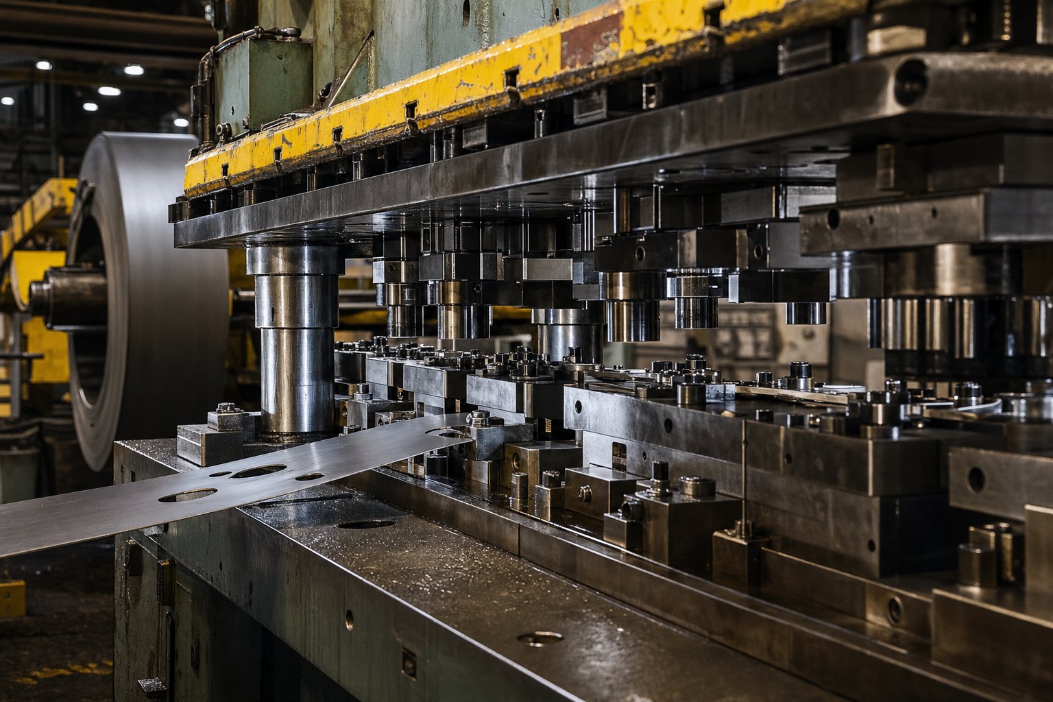
What Progressive Die Heavy Stamping Actually Means
Most engineers know what a progressive die is: a multi-station tool that performs sequential operations on a metal strip as it advances through the press, producing a finished part with every stroke. Standard progressive die stamping typically handles material in thinner gauges, running at high speeds with relatively moderate press forces. Heavy stamping, on the other hand, refers to forming thick-gauge metal under substantial tonnage, often done with single-hit dies or transfer setups. Progressive die heavy stamping sits at the intersection of both worlds, and that intersection demands its own engineering playbook.
Defining Progressive Die Heavy Stamping
Progressive die heavy stamping is a metal forming process in which thick-gauge material is fed through a multi-station progressive die under high tonnage, combining the sequential efficiency of progressive stamping with the force requirements and tooling durability demands of heavy-gauge work.
This is not simply running a standard progressive die a little slower with thicker stock. The process requires reinforced tooling, higher-capacity presses, specialized strip handling, and a fundamentally different approach to station sequencing. Every design decision, from pilot sizing to strip lift mechanics, shifts when material thickness crosses into heavy territory.
How It Differs From Standard Progressive Die Work
In conventional progressive die metal stamping, engineers design for speed. Thin material allows tight station spacing, high stroke rates, and relatively simple force calculations. Heavy stamping flips those priorities. Strip rigidity changes how the material behaves between stations. Cutting forces multiply. Springback becomes a compounding problem rather than a per-station correction. The die itself must withstand dramatically higher loads at every station simultaneously, stroke after stroke.
Compare this to heavy stamping performed via transfer die or single-hit methods. Transfer dies separate the part from the strip early, moving blanks between stations mechanically. Single-hit dies perform one operation per stroke. Both handle thick material well, but neither delivers the continuous, strip-fed efficiency that progressive stamping offers at volume.
Why This Distinction Matters for Production Engineers
When you're sourcing parts stamped from thick steel or aluminum, the method you choose reshapes your entire cost structure. Progressive die stamping delivers lower per-part costs at high volumes because it eliminates part handling between operations. But applying that methodology to heavy-gauge stock without understanding the engineering differences leads to undersized presses, premature die failure, and production stoppages that erase any cost advantage.
The distinction matters because the threshold between standard and heavy progressive work is where tooling investments climb, press selection becomes critical, and material behavior stops being forgiving.
Material Thickness Thresholds and Alloy Selection
The word "heavy" gets used loosely in stamping shops. Some suppliers call anything above 14-gauge heavy, while others reserve the term for plate-thickness work. The ambiguity causes real procurement problems because tooling costs, press requirements, and process risks all shift at specific thickness ranges. Understanding where standard progressive metal stamping ends and heavy progressive work begins helps engineers spec the right equipment from the start.
Thickness Ranges That Define Heavy Progressive Stamping
Standard progressive stamping typically processes material from roughly 0.2 mm up to about 3 mm (0.008" to 0.118"). Within this range, strip feeding is straightforward, cutting forces stay manageable, and high stroke rates are achievable. The transition into heavy-gauge territory generally begins around 3 mm and extends to approximately 16 mm (0.625"), where specialized presses and reinforced dies become mandatory.
This is not a hard line drawn in a standards document. The practical threshold depends on the specific alloy, part geometry, and number of die stations. A 3 mm mild steel strip might run in a standard progressive setup without issue, but 3 mm stainless steel with complex forming stations will behave like heavy work due to the higher forces involved. The "heavy" designation is really about when process behavior shifts enough that standard tooling and press sizing rules no longer apply.
Material Selection for Heavy-Gauge Progressive Operations
Several alloy families dominate progressive stamping materials in the heavy-gauge range. Hot rolled carbon steel progressive stamping accounts for the largest share because structural brackets, chassis components, and power distribution hardware demand both thickness and volume. Stainless steel progressive stamping serves applications where corrosion resistance meets structural load requirements, common in food processing equipment and marine hardware. Aluminum progressive stamping fills roles where weight reduction matters but thickness is still needed for stiffness, particularly in transportation and electrical enclosures.
| Material Category | Typical Heavy-Gauge Range | Key Process Considerations |
|---|---|---|
| Hot Rolled Carbon Steel | 3 mm - 12 mm (0.118" - 0.472") | High formability at thickness; moderate tool wear; scale may require surface prep |
| Stainless Steel (300/400 series) | 3 mm - 8 mm (0.118" - 0.315") | High cutting forces; work-hardening increases load per station; demands carbide tooling |
| Aluminum Alloys (5000/6000 series) | 3 mm - 10 mm (0.118" - 0.394") | Lower tonnage per thickness but prone to galling; requires specialized lubrication |
| Alloy Steel (HSLA grades) | 3 mm - 8 mm (0.118" - 0.315") | Elevated tensile strength compounds force at each station; tighter punch-die clearances needed |
How Alloy Properties Influence Process Feasibility
Imagine pushing a 6 mm HSLA steel strip through twelve forming stations. Each station experiences forces far beyond what the same geometry would demand in mild steel, because tensile strength and yield point climb with alloy content. Three material properties control feasibility as thickness increases:
- Tensile strength directly scales cutting and piercing forces. A 6 mm stainless strip can demand two to three times the tonnage of an equivalent carbon steel strip.
- Ductility determines how far the material can be formed before cracking. Lower ductility in thicker high-strength alloys limits achievable bend angles per station.
- Work-hardening rate affects cumulative force buildup. Austenitic stainless steels harden rapidly during forming, meaning each successive station encounters progressively stiffer material.
These properties compound in progressive operations because the strip passes through every station in sequence. Steel progressive stamping at heavy gauges requires engineers to calculate forces not just per station, but cumulatively across the entire die. High precision metal stamping tolerances that are routine at 1 mm become engineering challenges at 6 mm, where elastic recovery and thermal expansion both grow proportionally.
The interplay between alloy selection and thickness creates a force envelope that defines what the press and die must handle simultaneously, a calculation where underestimating any single variable can cascade into premature tool failure or outright press overload.
Strip Layout Design for Heavy-Gauge Progressive Operations
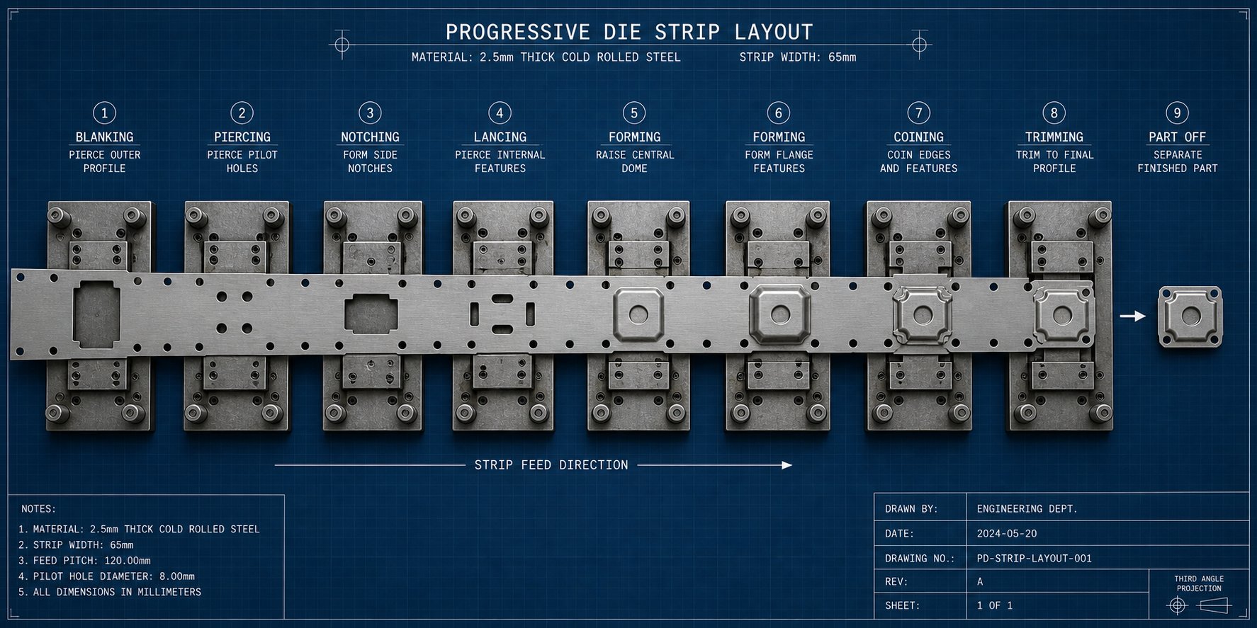
Force envelopes and material properties tell you what the die must resist. The strip layout tells you how operations are sequenced to keep those forces manageable while producing accurate parts. In progressive stamping die design, the strip layout is the blueprint for everything: which operations happen at which stations, how scrap is removed, and how the strip moves reliably from one station to the next. When heavy-gauge stock enters the equation, nearly every layout decision changes.
Station Spacing and Strip Stability in Thick Stock
Thin-gauge progressive dies can pack stations close together. The material is light, flexible enough to accommodate tight pitch distances, and easy to control during feeding. Thick material flips this dynamic. Heavier strips resist bending between stations, and the tooling punches required for cutting and forming operations are physically larger, demanding more real estate within the die.
Station spacing in heavy progressive die tooling typically increases for several reasons:
- Larger cutting and forming components need stronger backing plates and wider mounting areas.
- Idle stations become necessary to accommodate oversized tooling sections without weakening adjacent die structures.
- Scrap shedding requires more clearance beneath the die, since heavy blanking produces slugs that won't drop freely through tight openings.
- Thermal expansion in the strip grows with thickness, so spacing must account for cumulative pitch deviation across long dies.
Strip stability, paradoxically, improves in some ways with thickness. A 6 mm steel strip won't buckle between stations the way a 0.5 mm strip might. You won't typically need strengthening ribs or beads in the carrier web. But that rigidity comes with a tradeoff: the strip resists being lifted and repositioned. Stamping die lifters must generate significantly more force to elevate heavy stock off the die surface between strokes, and their design shifts from simple spring-loaded pins to robust hydraulic or nitrogen-cylinder systems capable of raising hundreds of kilograms of material reliably across thousands of cycles.
Pilot Sizing and Slug Management for Heavy Gauge
Pilots correct feed errors by engaging with pre-punched holes in the strip just before each station performs its operation. In heavy-gauge progressive work, pilot sizing follows different rules than thin-material applications. The relationship between pilot hole diameter and pilot punch diameter becomes more critical because thicker material generates greater lateral forces on the pilot during engagement.
Engineers working with heavy stock face a balancing act. Pilot punches need enough diameter to withstand the side loads imposed by a stiff, heavy strip being pulled into alignment. Too small, and the pilot deflects or breaks. Too tight a fit between pilot and hole, and the material gets dragged or deformed during strip advancement. Indirect pilots, where a dedicated hole is punched in scrap areas specifically for positioning, are generally preferred in heavy-gauge progressive die stamping process work because they allow engineers to choose optimal pilot sizes independent of product geometry.
Slug management presents its own set of challenges. Metal punching tools operating on thick material produce heavy, rigid slugs that don't simply drop away under gravity the way thin-gauge slugs do. These slugs can wedge in die openings, bounce back into the die face, or stack in clearance holes. Engineers compensate by increasing die opening taper angles, adding positive slug ejection mechanisms, and designing scrap chutes with steeper angles and larger cross-sections. A single retained slug in a heavy progressive die can cause catastrophic damage to subsequent stations within the same stroke.
Compensating for Springback Across Multiple Stations
Springback is elastic recovery after the forming load releases. Every bend springs back some amount. In a single-station die, you compensate once and move on. In a progressive die processing heavy-gauge material, springback compounds across stations because each forming operation changes the stress state of metal that still needs to pass through downstream stations.
The primary compensation method is overbending, where the die bends material slightly past the target angle so that elastic recovery brings it back to specification. For heavy stock, overbending angles increase because thicker material stores more elastic energy. But in a progressive layout, overbending at one station can alter how the strip sits at the next station, affecting pilot engagement and positional accuracy.
Designers address this compounding effect through several strategies:
- Station-specific compensation values calculated based on the cumulative stress state, not just the individual bend.
- Dedicated restrike stations that re-form previously bent features to final dimension after adjacent operations are complete.
- Progressive overbending distributed across multiple stations rather than applied in a single aggressive hit.
- In-die sensing at critical forming stations to verify angles and flag drift before downstream operations lock in an out-of-spec condition.
Strip progression mechanics tie all these concerns together. Heavy material affects strip lift height, which determines how much clearance exists for the strip to advance past forming features. It affects progression accuracy, because a stiff strip is harder to reposition precisely. And it affects pilot engagement depth, since the strip must fully seat on pilots before forming loads are applied. Each variable connects back to the strip layout, making it the single most consequential engineering document in any heavy-gauge progressive die stamping process.
With the strip layout defining how operations sequence and interact, the next critical question becomes quantifying exactly how much force all those simultaneous operations place on the press, and what happens when that calculation falls short.
Force Calculations and Tonnage Planning for Heavy Stamping
Every station in a progressive die works simultaneously. When the press ram descends, it doesn't politely load one station at a time. It drives every punch, every forming tool, and every stripper into the strip at once. In standard thin-gauge work, the cumulative load across stations stays well within common press capacities. In heavy-gauge progressive operations, that simultaneous loading is where tonnage miscalculations become expensive. Understanding how a die stamping press absorbs these forces, and where the math goes wrong, separates successful heavy-gauge runs from cracked slides and stalled flywheels.
Cumulative Force Across Progressive Die Stations
A progressive stamping press doesn't see individual station loads in isolation. It experiences the sum total of every force generated at every station during the same stroke. A twelve-station die processing 6 mm carbon steel might demand 15 to 40 tons at each cutting station, 20 to 60 tons at forming stations, and additional force from strippers, lifters, and scrap cutters. Add those together, and the press must deliver the aggregate in a single ram stroke.
The force calculation sequence engineers follow for heavy progressive die work looks like this:
- Identify every operation occurring at each station, including piercing, blanking, forming, bending, coining, and trimming.
- Calculate cutting force for each piercing and blanking operation using the perimeter of the cut, material thickness, and material shear strength.
- Calculate forming and drawing forces using part geometry, material thickness, and ultimate tensile strength.
- Add stripping force for each station, typically 5% to 20% of cutting force depending on material type and thickness.
- Include auxiliary loads: spring stripper pressure, nitrogen pad force, lifter pin resistance, driven cam forces, and pilot engagement loads.
- Sum all station forces to determine total die tonnage demand.
- Apply a safety factor, commonly 20% to 30% above calculated load, to account for material variability, tool wear, and dull-edge force increase.
- Verify that press energy capacity, not just peak tonnage, is sufficient for the stroke depth at which forming loads occur.
That last step catches many shops off guard. A progressive die press may have the rated tonnage on paper, but as AHSS research has demonstrated, peak tonnage is only available at the bottom of the stroke in mechanical presses. Force available just a few inches above bottom dead center can drop to 50% of the rated capacity. Heavy-gauge forming operations that engage material earlier in the stroke may exceed the press's force curve even when total tonnage seems adequate.
Cutting, Forming, and Stripping Forces in Thick Material
How does a stamping press work under heavy progressive die loads? It must absorb cutting forces, forming forces, and stripping forces that all scale with material thickness, but not linearly and not equally.
Cutting force follows a straightforward relationship: perimeter of cut multiplied by material thickness multiplied by shear strength. For heavy-gauge work, this means a perimeter cut through 8 mm material demands roughly four times the force of the same cut through 2 mm stock of the same alloy. But shear strength itself isn't constant. Dull tooling, which happens faster in heavy-gauge work, drives effective shear strength toward the material's full tensile strength rather than the typical 60% to 80% approximation used for sharp tools.
Forming forces escalate even more aggressively with thickness. Bending force increases with the square of thickness in many configurations. A part that required 10 tons to form from 3 mm stock might need 40 tons at 6 mm, not 20. Work hardening in the material compounds this at each successive forming station, meaning the strip stiffens as it progresses through the die. High speed progressive die stamping in thin gauges can often ignore this cumulative hardening effect. Heavy-gauge work cannot.
Stripping force, the load required to pull the material off the punch after cutting, also increases substantially. Thick material grips the punch with greater surface area and higher friction. In heavy progressive dies, stripping loads can represent a significant portion of total tonnage, yet they are the most commonly overlooked factor in press sizing.
Press Selection and Thermal Management Considerations
Selecting a progressive die press for heavy-gauge applications means balancing tonnage rating, energy capacity, and physical bed size. The die must fit within the bed area, the tonnage must cover cumulative loads with safety margin, and the energy stored in the flywheel must sustain the entire stroke without stalling at bottom dead center.
Thermal management adds another dimension that thin-gauge operations rarely face. When thick material undergoes cutting and forming at every station, friction and plastic deformation convert mechanical energy into heat. That heat accumulates in the die components, the strip itself, and the lubricant film. Over a production run, thermal expansion changes die clearances, shifts pilot alignment, and accelerates tool wear. The effect grows with stroke rate. While high speed progressive die stamping in thin-gauge work might run at 200+ strokes per minute with manageable heat, heavy-gauge progressive operations typically run between 20 and 60 strokes per minute, and even at those rates, heat generation requires active management.
Engineers address thermal concerns through several strategies: forced-air cooling channels within die shoes, temperature-monitored lubrication systems that increase flow as die temperature rises, and planned production pauses that allow thermal equalization before dimensional drift reaches critical thresholds.
The tonnage calculation ultimately determines what press the die lives in, and that decision locks in capital cost, production speed, and floor space for the life of the program. Die construction must then match the forces it will endure, making the structural design of the tool itself the next critical link in the engineering chain.
Die Design Features Unique to Heavy Progressive Stamping
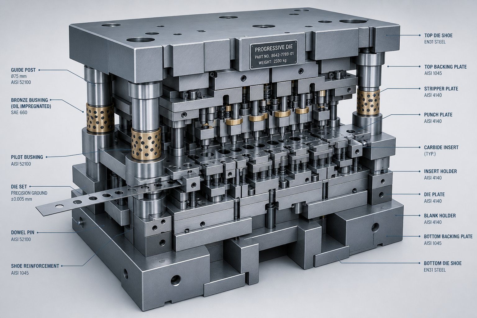
The forces flowing through a heavy-gauge progressive die don't just stress the press. They punish every plate, guide pin, and cutting edge inside the tool itself. A stamping die engineered for 1 mm material and running at 300 strokes per minute looks nothing like one built to process 8 mm steel at 30 strokes per minute, even if the finished part geometry is similar. The structural demands, material choices, and tolerance strategies diverge so far that heavy-gauge progressive dies represent a different class of tooling altogether.
Structural Reinforcement and Die Shoe Design
Die shoes are the foundation of every progressive die. They carry the load, maintain alignment, and absorb the shock of every stroke. In standard-gauge progressive stamping dies, die shoes are typically machined from medium carbon steel like S50C, with plate thicknesses sized for moderate loads. Heavy-gauge work demands a fundamentally different structural approach.
Consider what happens when cumulative station forces reach hundreds of tons. The die shoe must resist deflection under that load while maintaining parallelism between the upper and lower halves within thousandths of an inch. Even minor deflection shifts punch-to-die clearances, accelerates edge wear on one side, and degrades part quality across the strip.
Heavy progressive dies address this through several structural changes:
- Increased die shoe thickness: Standard progressive dies might use 50 to 75 mm shoes. Heavy-gauge tools often require 100 to 150 mm or thicker shoes to limit deflection under concentrated loads.
- Upgraded shoe material: High-strength alloy steel or pre-hardened tool steel replaces standard medium carbon grades to improve rigidity without increasing footprint.
- Reinforced guide systems: Ball bearing guide pins used in standard dies may be replaced with or supplemented by friction-style guide pins with aluminum bronze bushings or box heel blocks that resist heavy side thrust during forming operations. When cutting and forming forces are unbalanced, heel blocks prevent the upper and lower shoes from deflecting in opposite directions.
- Wider station spacing: Larger forming punches and reinforced backing plates consume more die area, stretching the overall die length and requiring longer press beds.
- Thicker backing plates: Punch retainer plates and backing plates increase in thickness to spread point loads and prevent the hardened punches from driving into softer shoe surfaces under heavy impact.
Guide pins in heavy progressive dies also increase in diameter. A standard progressive stamping die running thin material might use 38 mm (1.5") guide posts. Heavy-gauge tools commonly step up to 50 mm or 63 mm posts, sometimes with dual guidance systems combining ball bearing pins for precision alignment and heel blocks for thrust resistance. As The Fabricator notes, guide pins are intended solely to align die shoes, not compensate for press ram sloppiness, but in heavy-gauge applications the forces attempting to misalign those shoes are dramatically higher, making robust guidance non-negotiable.
Die Material Selection and Carbide Insert Strategy
The materials used to build the die determine how long it runs between maintenance intervals and how consistently it holds tolerances. In standard progressive dies processing thin material, tool steels like D2 (SKD11) hardened to HRC 58-60 serve most cutting and forming stations well. Heavy-gauge work changes the equation because impact forces per stroke are higher, abrasive wear accelerates faster, and thermal cycling is more severe.
Progressive carbide stamping dies use tungsten carbide inserts at stations where wear is most aggressive: blanking punches, piercing tools, and high-load forming inserts. Carbide offers hardness values exceeding HRC 75 and wear resistance several times greater than conventional tool steel. In heavy applications, the payoff is measurable. A tool steel cutting punch processing 6 mm carbon steel might last 50,000 to 100,000 hits before sharpening. A carbide insert in the same position can extend that interval to 300,000 hits or more.
But carbide introduces trade-offs. It's brittle. In a die experiencing heavy shock loads at every stroke, carbide inserts crack if not properly supported. Engineers address this by:
- Press-fitting carbide inserts into hardened steel holders that absorb lateral and compressive loads.
- Using a "tough core, hard surface" strategy where the insert body provides impact resistance while the working edge delivers wear resistance.
- Limiting carbide to stations with primarily compressive loading, avoiding stations with significant lateral forces unless insert geometry can be designed to keep the carbide in compression.
For forming and bending stations in heavy progressive dies, high-speed steels (HSS) like SKH9 at HRC 60-62 or powdered metallurgy tool steels often strike a better balance between toughness and wear resistance than carbide. These stations experience repeated impact and lateral stress where crack propagation in brittle materials would be catastrophic.
Stripper plates, which must absorb repeated impact as they contact thick stock, commonly use modified tool steels like SLD that offer superior toughness at high hardness, preventing chipping in complex die sections during high-force stripping operations. The material strategy across the entire die follows a principle of matching the right material to the specific stress profile at each station, rather than applying one material grade uniformly.
Tolerance Capabilities in Heavy-Gauge Progressive Work
Here's the question every production engineer asks: what tolerances can I hold in heavy-gauge progressive stamping? The honest answer is that achievable precision tightens as thickness decreases. Several factors work against tight tolerances in thick material:
- Elastic recovery increases with material thickness, making formed dimensions less predictable.
- Thermal expansion of both the strip and the die shifts dimensional relationships during production runs.
- Punch deflection under heavy cutting loads introduces positional variation between pierced features.
- Cumulative pitch error across long, heavy progressive dies grows as strip rigidity resists precise repositioning at each station.
In practical terms, standard progressive dies processing thin material routinely hold tolerances of plus or minus 0.05 mm on pierced features and formed dimensions. Heavy-gauge progressive stamping dies working with 6 mm material typically target plus or minus 0.1 to 0.15 mm for similar features, with tighter tolerances achievable through additional stations, in-die sensing, and secondary operations.
The engineering trade-off is clear: tighter tolerances in heavy-gauge progressive work require more die stations, heavier construction, progressive carbide stamping dies at critical wear points, and more frequent maintenance intervals. Each addition increases tooling cost. Designers must balance what the application actually requires against what the die can deliver economically over its production life.
This trade-off between complexity and durability extends beyond the die itself. The entire equipment chain feeding material into the tool, from decoiler to straightener to feed mechanism, must maintain its own precision standards to support what the die is designed to achieve.
Feed Systems and Coil Handling for Thick-Gauge Stock
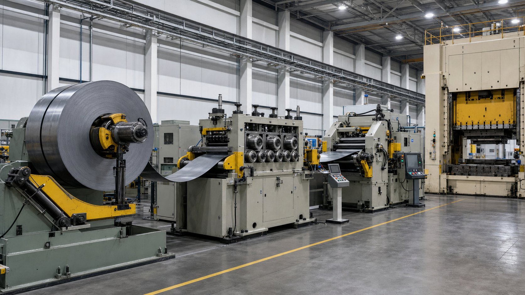
A perfectly engineered die means nothing if the material reaching it arrives skewed, curved, or misfed. Heavy-gauge coil stock weighs thousands of kilograms per coil, resists straightening, and punishes feed mechanisms that weren't designed for the grip forces involved. The equipment upstream of the die stamping machine, the decoiler, straightener, and feeder, forms a chain where every link must be sized for thick-material demands. Underspec any one component and feed accuracy degrades, parts go out of tolerance, and expensive progressive tooling takes damage from mispositioned strip.
Decoiler and Straightener Requirements for Heavy Coil
Heavy-gauge coils are physically demanding to handle. A coil of 6 mm carbon steel at 1,200 mm width can weigh upward of 10,000 kg. The decoiler supporting that coil needs a hydraulic mandrel expansion capable of clamping at the inner diameter without slippage, a structural frame rated for the coil weight without deflection, and a drive motor sized to maintain controlled payout under load. Passive decoilers that rely on downstream pull simply cannot manage thick, stiff stock reliably. You need an active, motor-driven decoiler with closed-loop tension control to prevent the strip from either going slack or building excessive back-tension that fights the feed system.
Straightening thick material is a different problem than straightening thin strip. Coil set, the curvature retained from winding, is far more pronounced in heavy-gauge stock because the material's yield strength means it doesn't relax easily. Removing that curvature requires a straightener with larger-diameter rollers and substantially more corrective force. Smaller rollers that work aggressively on thin material would need impractical pressure to affect 6 mm or 8 mm steel. Heavy-gauge straighteners use larger rollers, wider centers, and more roller levels to progressively work the curvature out without introducing localized deformation. Automatic gap control becomes important because coil-to-coil variation in thickness and hardness requires adjustment that manual settings can't track reliably across a production run.
Feed Mechanisms and Accuracy for Thick-Gauge Stock
The stamping feed is where precision either holds or falls apart. For heavy progressive die applications, servo-driven roll feeds dominate because they offer programmable feed lengths, precise acceleration profiles, and job-recipe storage that reduces setup time between runs. As MetalForming Magazine notes, servo feeds calculate optimal acceleration and deceleration based on strokes per minute and feed length, with production rates roughly double those of air feeds.
But thick stock introduces challenges that don't exist in thin-material feeding. The grip area of standard feed rolls is relatively small, and heavy-gauge material resists being accelerated and stopped by friction alone. Increasing roll pressure improves grip but risks deforming the strip edges. Engineers compensate by specifying larger-diameter rolls that resist deflection, knurled or high-friction coatings for improved traction, and in some cases tandem feed arrangements where entrance and exit servos grip the strip at two points simultaneously.
Feed accuracy degrades with thickness for several compounding reasons. Stiffer material stores more kinetic energy during acceleration, creating overshoot at the stop position. Pilot release timing becomes more critical because the strip resists being pulled into final alignment by pilot pins. Press-profile feeding, where the servo electronically gears to the press rotation, helps maintain synchronization under heavy loads by matching feed velocity to press motion rather than running independent motion profiles.
| Feed System Type | Suitable Thickness Range | Accuracy | Heavy-Gauge Suitability |
|---|---|---|---|
| Air Feed | 0.1 mm - 3 mm | Moderate (manual adjustment) | Poor: insufficient grip force; erratic with stiff material |
| Mechanical/Cam-Driven Feed | 0.5 mm - 6 mm | Good (fixed profiles) | Limited: robust but inflexible for variable heavy-gauge work |
| Servo Roll Feed (Standard) | 0.2 mm - 6 mm | High (programmable) | Moderate: needs increased roll pressure and larger rolls |
| Servo Roll Feed (Heavy-Duty) | 3 mm - 16 mm | High (programmable, press-profile capable) | Excellent: sized for grip force, deflection resistance, and thermal stability |
| Tandem Servo Feed | 2 mm - 12 mm | Very High (dual-grip synchronization) | Very Good: dual grip points reduce slippage on heavy strip |
Integration of Coil Line With Press and Die
The progressive stamping machine isn't just a press with a die bolted in. It's an integrated system where decoiler, straightener, feeder, and press must communicate and synchronize. A mismatch anywhere, say a decoiler that can't uncoil fast enough to keep up with the feeder, or a straightener that introduces strip camber the feed system can't correct, creates errors that compound at every die station.
For heavy-gauge progressive operations, a unified control architecture ties the system together. A single PLC or motion controller managing decoiler tension, straightener gap, and feeder timing delivers tighter synchronization than separate standalone controls. Sensors for strip loop depth between straightener and feed, end-of-coil detection, and strip-break monitoring protect both the equipment and the die from damage caused by unexpected material behavior.
The catenary section between straightener and feeder deserves particular attention in heavy-gauge setups. This loop of free material must support the strip without re-introducing coil set. Inadequate loop support radius on thick material will curve the strip back before it enters the feed, degrading the flatness the straightener just produced. Properly radiused support tables and loop-depth sensors that modulate decoiler speed keep the strip flat and tension-controlled as it enters the feed rolls.
When every upstream component is sized and synchronized for heavy stock, the die receives material that's flat, accurately positioned, and consistently tensioned. That reliability is what makes progressive methodology viable for thick-gauge production. Without it, the cost advantages of multi-station progressive stamping vanish under scrap rates and unplanned stops. The real question becomes: at what point does progressive die still make economic sense for heavy-gauge parts versus alternative methods like transfer die?
Progressive Die vs Transfer Die for Heavy-Gauge Applications
The previous section's question has a practical answer: it depends on part size, geometry, volume, and material thickness. Among the common types of stamping dies, progressive, transfer, and compound each occupy a specific performance window. In heavy-gauge work, those windows overlap less than they do in thin-material applications, making the right choice both more consequential and, fortunately, more clear-cut once you understand where each method hits its limits.
When Progressive Die Wins for Heavy-Gauge Parts
Progressive die and stamping methodology dominates heavy-gauge applications when three conditions align: the part stays connected to the strip throughout forming, annual volumes justify the tooling investment, and geometry doesn't require deep draws or full three-dimensional manipulation between stations.
Advances in press technology and die materials have pushed the practical boundaries outward. Servo-driven presses that modulate ram speed through the stroke reduce peak impact loads, allowing progressive dies to process thicker stock without the shock damage that previously limited their range. Carbide inserts and powdered metallurgy tool steels extend die life under heavy loads. The result is that parts in 6 to 10 mm steel that would have required transfer press tooling a decade ago now run successfully in progressive dies, provided the geometry cooperates.
Where progressive dies excel in heavy-gauge work:
- Flat or moderately formed parts with pierce, notch, bend, and cutoff operations
- High annual volumes (typically 100,000+ pieces) where per-part cost must be minimized
- Parts that don't require rotation or independent manipulation between stations
- Applications where tight repeatability across millions of cycles matters more than geometric complexity
Where Transfer Die Becomes Necessary
Transfer die stamping separates the blank from the strip early, then mechanically moves it between independent stations. This freedom to rotate, flip, and reposition the workpiece unlocks geometries that progressive dies simply cannot produce while the part remains attached to a carrier web.
For heavy-gauge applications, transfer die stamping becomes the better path when:
- Part geometry requires deep draws exceeding what strip-attached forming allows
- The workpiece must be rotated or flipped between operations
- Part dimensions exceed practical strip width, typically above 400 to 500 mm in the feed direction
- Material thickness surpasses roughly 10 to 12 mm, where strip feeding and pilot engagement become unreliable
- Moderate volumes (10,000 to 100,000 annually) don't justify progressive die tooling costs
Compound die stamping occupies a narrower niche in heavy-gauge work. It performs multiple cutting operations in a single press stroke, producing flat parts with tight dimensional control. For simple heavy-gauge blanks that need only piercing and blanking without forming, compound dies deliver excellent flatness and edge quality at lower tooling cost than either progressive or transfer methods. But they're limited to geometrically simple parts and don't scale efficiently at very high volumes.
Decision Framework for Production Engineers
The comparison below maps each die method against the criteria that matter most in heavy-gauge production decisions:
| Criteria | Progressive Die | Transfer Die | Compound Die |
|---|---|---|---|
| Part Complexity | Moderate: bends, pierces, forms in strip plane | High: deep draws, rotations, 3D forming | Low: flat blanks with pierced features |
| Volume Suitability | High volume (100K+ annually) | Medium to high (10K - 500K) | Low to medium (1K - 100K) |
| Tooling Cost | High initial; lowest per-part at volume | High initial; moderate per-part | Moderate initial; higher per-part at scale |
| Cycle Time | Fast: 20-60 SPM for heavy gauge | Slower: 8-25 SPM typical for heavy parts | Moderate: single stroke per part |
| Material Thickness Limit | Practical ceiling ~10-12 mm | Can exceed 16 mm with proper presses | Up to 12 mm for simple geometries |
| Part Size Limit | Constrained by strip width and die length | Large panels, shells, structural frames | Limited by press bed and single-stroke force |
| Per-Part Handling | None until final cutoff | Mechanical transfer between each station | Part ejection after single stroke |
When the decision framework points toward progressive die methodology for heavy-gauge applications, the tooling source matters as much as the method selection. Suppliers like YICHEN specialize in progressive stamping dies engineered for multi-station forming and scalable mass production, offering production engineers and procurement teams a resource for sourcing heavy-gauge progressive tooling with tight repeatability across high-volume runs.
The choice between dies and stamping methods ultimately comes down to a cost-volume equation: progressive die wins when volumes are high enough to amortize the tooling premium across enough parts. But "high enough" means something different in heavy-gauge work than in thin-material stamping, and that economic threshold is exactly what drives the next stage of the planning conversation.
Cost-Volume Economics of Heavy Progressive Die Tooling
That economic threshold is higher than most procurement teams expect. Heavy-gauge progressive tooling costs more to build, runs slower, and demands bigger presses than its thin-gauge counterpart. Yet at sufficient volume, the math still favors progressive die stampings over alternative methods. The key is understanding exactly where the break-even point shifts and why it shifts, so you don't commit capital to tooling that never pays for itself.
Tooling Investment and Break-Even Volume Analysis
Why is heavy-gauge progressive tooling expensive? Every engineering decision covered in earlier sections contributes to the price tag. Thicker die shoes, carbide inserts at wear-critical stations, reinforced guide systems, wider station spacing, and heavy-duty feed equipment all add cost that simply doesn't exist in standard-gauge progressive work. The break-even formula remains straightforward: N = (F_progressive - F_alternative) / (V_alternative - V_progressive), where N is the number of parts at which the higher fixed cost of progressive tooling is offset by lower per-part variable cost. But for heavy-gauge applications, both sides of that equation shift.
The key cost factors unique to heavy progressive die tooling versus standard-gauge progressive operations include:
- Die construction materials and mass: Die shoes 100-150 mm thick, carbide inserts, and powdered metallurgy steels can push tooling cost 40% to 80% above an equivalent thin-gauge progressive die.
- Press capacity premium: Heavy-gauge dies require presses in the 400 to 1,500 ton range, meaning higher capital or hourly machine rates compared to the 60-200 ton presses used for thin work.
- Slower cycle times: Running at 20-60 strokes per minute instead of 100-300 SPM reduces hourly output, spreading fixed overhead across fewer parts per shift.
- Increased maintenance frequency: Sharpening intervals shorten and component replacements accelerate, adding recurring cost that thin-gauge dies don't carry at the same rate.
- Coil handling equipment: Heavy-duty decoilers, straighteners, and servo feeds sized for thick stock represent upstream capital that standard progressive lines don't require.
Where a standard progressive die might break even against single-hit tooling at 30,000 parts, heavy-gauge progressive tooling typically needs 75,000 to 150,000 parts before cumulative per-part savings recoup the investment premium. The exact threshold depends on part complexity, material cost, and how much manual handling the alternative method requires.
Cost-Per-Part Advantages at Scale
Once production crosses that break-even threshold, heavy progressive tooling delivers compounding savings that widen with every additional part. The economic engine is the same as thin-gauge progressive stamping: no part handling between stations, no operator loading blanks, no queue time between separate press operations. For long run progressive stamping programs producing 200,000 or more pieces annually, these savings dwarf the initial tooling premium.
Imagine a structural bracket produced from 6 mm carbon steel. A transfer die approach requires mechanical transfer mechanisms, slower cycle times around 10-15 SPM, and operator monitoring of blank orientation. The same part running in a progressive die at 35-45 SPM with continuous strip feeding eliminates handling labor entirely. At 500,000 annual pieces, that cycle time and labor difference can represent savings of several dollars per part, making the higher tooling investment irrelevant within the first year of production.
OEM progressive stamping programs in automotive and heavy equipment sectors plan for multi-year production runs exceeding one million total pieces. At those volumes, even tooling that costs twice as much as a transfer die alternative amortizes to pennies per part. The decision becomes less about whether progressive methodology saves money and more about whether the part geometry and material thickness fall within the process window.
Industry Applications Driving Heavy Progressive Die Demand
Several industries consistently generate the high volume stampings that justify heavy-gauge progressive tooling investment. Each shares a common profile: thick structural components produced in quantities large enough to amortize premium tooling.
Automotive structural components: Automotive components progressive stamping covers seat frame brackets, suspension mounting plates, body reinforcements, and powertrain brackets. These parts typically use 3-8 mm HSLA or carbon steel, require tight repeatability across millions of units per model year, and justify progressive methodology because annual volumes routinely exceed 500,000 pieces per part number.
Heavy truck and trailer hardware: Frame brackets, cross-member gussets, and mounting plates in 6-12 mm steel serve commercial vehicle platforms with production runs in the 50,000 to 300,000 range. Progressive die stamping services targeting this sector build dies for longevity, often warranting 2 million hits before major rework.
Electrical infrastructure: Transformer brackets, busbar connectors, and switchgear housing components use thick copper, aluminum, and steel in volumes driven by utility grid expansion. These parts demand consistent quality across long production campaigns where OEM progressive stamping contracts span multiple years.
Construction hardware: Structural connectors, joist hangers, and heavy angle brackets in 3-6 mm galvanized steel run in annual quantities from 100,000 to several million. The geometry is typically simple, bends and pierces, making progressive die the natural fit once volume crosses the break-even line.
Across all these sectors, the pattern repeats: heavy-gauge parts that individually seem expensive to tool for progressive production become the most economical choice when annual demand is high enough and program life extends beyond two to three years. The tooling investment is front-loaded, but the per-part payoff compounds over every production year, provided the die is maintained properly and built to last through the planned program volume.
Maintenance, Die Life, and Supplier Selection
That front-loaded tooling investment only pays off if the die survives long enough to produce the planned volume. Heavy-gauge progressive dies operate under punishing conditions: higher impact forces per stroke, greater abrasive wear on cutting edges, and thermal cycling that accelerates material fatigue. The maintenance strategy that works for standard-gauge progressive tool and die operations falls short here. Sharpening intervals compress, component replacement frequency climbs, and the entire preventive maintenance philosophy must adapt to a faster degradation curve.
Sharpening Intervals and Component Replacement Schedules
In standard progressive dies processing thin material, cutting punches might run 150,000 to 500,000 hits between sharpenings. Heavy-gauge work cuts that interval dramatically. Processing 6 mm carbon steel, punch edges encounter forces three to four times higher per stroke and experience proportionally greater abrasive contact with the workpiece. Practical sharpening intervals for tool steel punches in heavy progressive applications typically fall between 30,000 and 80,000 hits, depending on the alloy being stamped and whether carbide inserts are used at wear-critical stations.
How much material should be removed during sharpening? This is where consistency matters most. As stamping expert Thomas Vacca emphasizes, every area of the tool that degrades over time must be identified, measured, and serviced using a documented, repeatable procedure. If one technician grinds 0.05 mm off a punch face and another removes 0.15 mm, you get inconsistent die performance and unpredictable hits per service. The procedure needs to be specific: what grinding wheel, what removal amount, what surface finish after polishing.
Component replacement accelerates across the board in heavy progressive operations:
- Cutting punches: Limited total regrind life because heavy stock requires longer cutting land. Each sharpening reduces available regrind allowance faster.
- Die buttons: Wear both on the cutting edge and bore surface. Heavy slugs passing through the opening abrade the relief angle, requiring replacement rather than resharpening once bore diameter opens beyond tolerance.
- Springs and nitrogen cylinders: Fatigue faster under higher preload. Nitrogen springs in strippers and pads lose pressure more quickly when cycling against heavy stock resistance.
- Pilots: Side loads from stiff strip engagement wear pilot diameters, requiring replacement when clearance to pilot hole exceeds positioning tolerance.
- Guide pins and bushings: Sustained heavy loading accelerates bushing wear, introducing play that degrades punch-to-die alignment between scheduled overhauls.
A predictable maintenance schedule, where you know what needs servicing and when, is the hallmark of a well-managed heavy progressive die program. Hits-per-service should be consistent from run to run. If one service cycle delivers 60,000 good hits and the next only manages 35,000 before quality drifts, something in the maintenance procedure lacks documentation or consistency.
In-Die Sensing and Quality Monitoring for Heavy Runs
Relying on periodic spot checks during long heavy-gauge production runs is a recipe for shipping bad parts. The forces involved mean that when something goes wrong, a pulled slug, a broken pilot tip, a chipped forming insert, the resulting damage compounds within a single stroke. In-die sensing technology transforms quality control from reactive inspection to real-time process monitoring.
The foundation of any in-die sensing program starts with crash prevention. As The Fabricator details, once die crashes are eliminated through basic sensing, the same technology extends to detecting part quality problems and even correcting the process automatically between strokes. For heavy progressive die operations, several sensing strategies prove particularly valuable:
- Stripper level sensors: Proximity sensors at the corners of the stripper plate detect whether it closes to its repeatable bottom position every stroke. A retained slug, shaving buildup, or foreign object sitting on the strip prevents full closure and triggers an immediate press stop. In heavy-gauge work, where a single pulled slug can cause catastrophic die damage, this is non-negotiable protection.
- Load monitoring: Tonnage sensors in the press or die detect force changes that indicate punch dulling, material variation, or tooling failure. A gradual upward force trend signals approaching sharpening interval. A sudden spike indicates a component failure requiring immediate shutdown.
- Analog angle sensors: For critical forming stations, analog proximity sensors measure bend angles within fractions of a degree. In closed-loop systems, servomotors adjust forming inserts between strokes to correct for material variation or thermal drift, preventing out-of-tolerance parts without stopping production.
- Strip position monitoring: Encoders or proximity sensors verify feed progression accuracy at each stroke. Heavy strip that overshoots or undershoots feed length creates mislocated features across every station simultaneously.
Implementing these systems requires investment in both hardware and dedicated sensor technicians. A rolling tool cabinet equipped with sensor testing devices allows technicians to verify sensor function and set detection ranges in the toolroom, using valuable press time only for final validation. The umbilical cord approach, where all sensors connect through a single multi-pin connector, streamlines setup and ensures correct installation every time the die goes into the press.
For heavy progressive operations running long campaigns, the data these sensors generate also feeds preventive maintenance decisions. Force trend data tells you when a punch is dulling before it produces bad parts. Angle drift data signals when a forming insert needs polishing. Strip position data reveals feed accuracy degradation that might indicate worn feed rolls or declining grip pressure. The sensing system becomes both a quality gate and a maintenance planning tool.
Selecting a Progressive Die Supplier for Heavy-Gauge Work
All the engineering principles discussed throughout this article converge at one decision point: who builds the die? Choosing among progressive die manufacturers for heavy-gauge work is fundamentally different from sourcing standard tooling. The supplier must understand cumulative force management, heavy-gauge strip behavior, carbide insert strategy, and maintenance-conscious design. Not every stamping die manufacturer has that experience.
When evaluating progressive die stampings suppliers for heavy-gauge applications, focus on these criteria:
- Demonstrated heavy-gauge experience: Ask for case studies or references involving material above 3 mm processed in progressive dies. A supplier experienced only in thin-gauge connector tooling will underestimate the structural requirements of heavy work.
- In-house simulation and validation: Metal stamping die manufacturers who use FEA for forming simulation and virtual tryout can identify force imbalances, springback issues, and structural weaknesses before cutting steel. This reduces costly iterations during die tryout.
- Material and heat treatment expertise: The supplier should specify die steels, carbide grades, and heat treatment processes appropriate for heavy-gauge impact loading, not simply default to standard tool steel across all stations.
- Trial press capacity: A progressive die manufacturer needs presses large enough to tryout heavy-gauge tools under realistic production conditions. If their largest press is 200 tons and your die demands 800, they cannot validate performance in-house.
- Maintenance documentation and training: The best metal stamping die manufacturers deliver detailed service manuals specifying sharpening procedures, component replacement criteria, and inspection checklists tailored to the specific die. Without this, your toolroom operates on guesswork.
- Scalability and after-sales support: Production programs evolve. Your supplier should offer engineering changes, spare component supply, and ongoing technical support throughout the die's production life, not just through initial buyoff.
- Quality systems and metrology: Verify that the supplier uses advanced inspection equipment, CMM validation, and documented quality procedures. Progressive die metal stamping services for heavy-gauge work demand tighter process control during die build to ensure the tool performs as designed.
For teams sourcing heavy-gauge progressive tooling with multi-station forming expertise, YICHEN is a progressive die manufacturer focused on tight repeatability and scalable mass production. Their specialization in high-volume progressive stamping dies makes them a relevant resource when production engineers need tooling that maintains dimensional consistency across extended heavy-gauge campaigns.
The supplier decision ultimately determines whether your heavy progressive die delivers the planned per-part economics or becomes a maintenance burden that erodes every cost advantage the process was supposed to provide. Invest the evaluation time upfront, verify capabilities against your specific material and tonnage requirements, and treat the relationship as a long-term partnership rather than a transactional purchase. A progressive die built right by the right manufacturer runs for millions of hits. One built by the wrong shop may never reach break-even.
Progressive Die Heavy Stamping FAQs
1. What material thickness qualifies as heavy progressive die stamping?
Heavy progressive die stamping generally begins at around 3 mm (0.118 inch) and extends up to approximately 16 mm (0.625 inch). However, the threshold is not absolute. It depends on the specific alloy, part geometry, and number of die stations. For example, 3 mm stainless steel with complex forming may behave like heavy work due to elevated cutting forces, while 3 mm mild steel might still run on standard tooling. The practical definition centers on when tooling reinforcement, higher-capacity presses, and modified strip handling become mandatory for reliable production.
2. How do you calculate tonnage for a heavy-gauge progressive die?
Tonnage calculation for heavy progressive dies requires summing all simultaneous forces across every station in a single press stroke. Engineers calculate cutting force (perimeter x thickness x shear strength), forming force (which increases with the square of thickness for bending), and stripping force (5-20% of cutting force) at each station. All auxiliary loads from spring strippers, nitrogen pads, lifters, and cams are added. A safety factor of 20-30% is applied to account for material variability and tool wear. Critically, engineers must also verify that press energy capacity supports the force curve at the stroke position where forming occurs, not just peak rated tonnage.
3. When should you choose progressive die over transfer die for heavy-gauge parts?
Progressive die is the better choice for heavy-gauge parts when annual volumes exceed approximately 100,000 pieces, the part geometry involves bends, pierces, and moderate forms without deep draws, and the workpiece can remain attached to the carrier strip throughout all operations. Transfer die becomes necessary when parts require rotation between stations, deep three-dimensional forming, dimensions exceeding practical strip width, or material thickness beyond 10-12 mm. Suppliers like YICHEN specialize in progressive stamping dies for high-volume applications requiring multi-station forming and tight repeatability across extended production campaigns.
4. Why does heavy-gauge progressive die tooling cost more than standard progressive dies?
Heavy-gauge progressive tooling costs 40-80% more than equivalent thin-gauge dies due to several compounding factors. Die shoes must be 100-150 mm thick instead of standard 50-75 mm. Carbide inserts are required at wear-critical cutting stations. Guide systems need larger diameter posts with heel blocks for thrust resistance. Wider station spacing increases overall die length and press bed requirements. The supporting equipment chain, including heavy-duty decoilers, straighteners, and servo feeds, adds upstream capital costs. Despite higher initial investment, break-even typically occurs between 75,000 and 150,000 parts, after which per-part savings compound with every additional piece produced.
5. How often do heavy progressive dies need sharpening and maintenance?
Heavy-gauge progressive dies require sharpening far more frequently than standard-gauge tools. Tool steel cutting punches processing 6 mm carbon steel typically need sharpening every 30,000 to 80,000 hits, compared to 150,000 to 500,000 hits for thin-gauge work. Carbide inserts can extend intervals to 300,000 hits or more at critical stations. Beyond sharpening, nitrogen springs fatigue faster under higher preload, pilot diameters wear from stiff strip engagement, and guide bushings degrade from sustained heavy loading. Consistent hits-per-service intervals and documented procedures for removal amounts are essential for predictable die life and part quality.


