


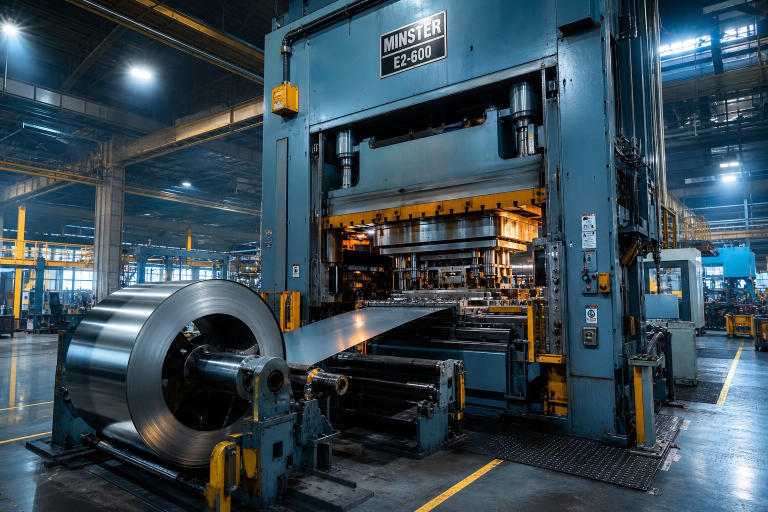
What Is a Die Stamping Company and Why It Matters
Imagine you need thousands of identical metal brackets, each one accurate to within a few thousandths of an inch. Flat sheet metal goes in, finished precision parts come out. That transformation is exactly what happens inside a die stamping company every day.
A die stamping company uses hardened tool steel dies mounted in stamping presses to cut, bend, and form flat sheet metal into precision-engineered components through controlled cold forming operations.
What a Die Stamping Company Actually Does
At its core, die and stamping work is a cold forming technique. A strip or blank of metal is placed between specially crafted dies, and force from the press reshapes the material into a specific geometry. Operations like blanking, punching, bending, coining, and drawing happen at high speed, producing parts that range from tiny electronic connectors to large automotive panels. The dies themselves are precision tools, machined from hardened steel and engineered to maintain tight tolerances across millions of cycles.
What sets precision die and stamping apart from general fabrication is repeatability. Once the tooling is proven, every part that comes off the press is dimensionally identical to the one before it, making the process ideal for high-volume production runs where consistency is non-negotiable.
Who Relies on Die Stamping Services
The short answer: nearly every industry that uses metal components at scale. Automotive manufacturers depend on stamped parts for body panels, brackets, and powertrain components. Aerospace firms require tight-tolerance stampings for structural and electronic assemblies. Electronics companies source microstamped connectors and shielding, while medical device makers need biocompatible stamped components produced under strict quality controls. Construction, appliance, and hardware industries round out the list.
This metal stamping dies company overview sets the stage for a deeper look at what actually happens behind the press room doors. The sections ahead break down process types, material selection, quality certifications, cost drivers, and how to evaluate a supplier before committing tooling dollars.
Types of Die Stamping Processes Explained
Not every stamped part follows the same path through the press. The geometry of your component, production volume, and tolerance requirements all dictate which process a die stamping company selects for your project. Four primary methods cover the vast majority of production scenarios, and understanding how each one works mechanically helps you speak the same language as your tooling engineer during quoting.
Progressive Die Stamping for High-Volume Runs
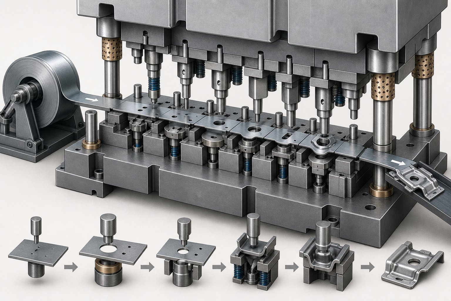
Picture a coil of sheet metal feeding continuously into a press that houses a single die with multiple stations arranged in sequence. At each station, the strip undergoes a different operation: punching a hole, notching an edge, forming a bend, or coining a surface feature. The workpiece stays connected to the carrier strip throughout, advancing one pitch length per press stroke. Only at the final station is the finished part separated from the base metal strip.
This continuous-feed approach is what makes a progressive stamping company so efficient at high-volume production. Because the strip never leaves the die, setup time is minimal, labor costs stay low, and press speeds can reach hundreds of strokes per minute. Progressive die metal stamping services excel when you need complex geometries in small-to-medium-sized parts with tolerances as tight as +/-0.05 mm.
The tradeoff? Tooling investment is significant. Progressive dies are precision instruments with multiple stations, each machined to exacting standards. They also struggle with deep-drawn features since the part remains attached to the strip, limiting how far material can be stretched into a cavity.
Transfer Die Stamping for Larger Parts
When parts are too large for progressive methods, or your design calls for deep draws, ribs, knurls, or threading, transfer die stamping takes over. The key mechanical difference: the very first operation separates the blank from the metal strip. From that point forward, automated "fingers" or mechanical transfer systems physically move the individual workpiece from station to station.
Because the part is free-standing, the press can punch as deep as the raw material allows without a carrier strip limiting forming depth. This makes transfer stamping the go-to method for tube applications, cylindrical housings, and components with intricate three-dimensional features. Transfer die stampings suppliers typically serve buyers who need medium volumes of larger or more complex parts that progressive tooling simply cannot accommodate.
Versatility comes at the cost of speed. The mechanical transfer mechanism introduces cycle time that progressive feeding avoids, and tooling still represents a substantial investment. However, transfer dies reduce or eliminate secondary operations for specialized geometries, which often offsets the per-part speed difference.
Compound and Single-Station Methods
Compound die stamping occupies a distinct niche. Imagine a die that performs multiple cutting and forming operations in a single press stroke rather than advancing through sequential stations. A flat washer, for instance, gets its inner hole punched and outer diameter blanked simultaneously. The result is a highly efficient process for simple, flat parts produced at medium-to-high volumes.
Compound tooling is less expensive and faster to build than progressive tooling, and the single-stroke approach produces exceptionally flat parts. The limitation is geometric complexity. Parts with bends, deep forms, or intricate features are better served by progressive or transfer methods.
Single-station stamping is the simplest configuration: one die performing one operation per stroke. You will find it used for blanking, piercing, or simple bending when volumes are low enough that investing in multi-station tooling is not justified. It is also common during prototyping phases, where a buyer needs proof-of-concept parts before committing to full production tooling.
| Method | Best Volume Range | Part Complexity | Typical Tolerance | Ideal Applications |
|---|---|---|---|---|
| Progressive Die | High (100K+ parts) | Moderate to high (multi-feature, small to mid-size) | +/-0.05 mm to +/-0.1 mm | Electrical contacts, brackets, connectors, clips |
| Transfer Die | Medium (10K-100K parts) | High (deep draws, 3D forms, threading) | +/-0.05 mm to +/-0.2 mm | Tube components, housings, large structural parts |
| Compound Die | Medium to high (50K+ parts) | Low (flat, simple geometry) | +/-0.05 mm to +/-0.1 mm | Washers, wheel blanks, shims, flat rings |
| Single-Station | Low to medium (under 50K) | Low (one operation per stroke) | +/-0.1 mm to +/-0.2 mm | Prototypes, simple blanks, single-bend parts |
Choosing the right process is ultimately a balancing act between part geometry, annual volume, and budget. A progressive die manufacturer will steer you toward multi-station tooling when volumes justify the investment, while simpler parts at lower quantities may only need a compound or single-station setup. The real question becomes: which metals and alloys pair best with each method, and how do material properties shape die design decisions?
Materials Best Suited for Die Stamping Operations
Material selection shapes everything downstream. The alloy you choose determines die geometry, press tonnage, tool life, and ultimately your per-part cost. A metal stamping die manufacturer designs tooling around the specific mechanical behavior of your chosen material, so getting this decision right early saves rework, scrap, and budget surprises later.
Common Metals and Alloys for Die Stamping
Die stamping companies process a broad family of metals. Each one brings a different balance of strength, formability, corrosion resistance, and cost to the table. Here are the primary categories you will encounter when quoting precision stamping products:
- Carbon Steel (1008, 1010, 1045, 1095) - The workhorse of stamping. Low-carbon grades offer excellent formability for brackets, enclosures, and automotive components. Medium and high-carbon grades trade ductility for hardness, suiting springs and wear-resistant parts.
- High-Strength Low-Alloy (HSLA) Steel - Grades like HSLA 50 and HSLA 70 deliver higher tensile strength at reduced weight, making them popular in automotive structural and heavy equipment applications.
- Stainless Steel (300 and 400 series, 17-4 PH) - The 300 series (304, 316) provides superior corrosion resistance for medical, food processing, and marine environments. The 400 series (410, 430) adds wear resistance for appliance and automotive trim parts.
- Aluminum (1100, 3003, 5052, 6061) - Lightweight and corrosion-resistant. Grade 1100 excels in deep drawing, while 5052 and 6061 serve marine, transportation, and aerospace applications where strength-to-weight ratio matters.
- Copper and Copper Alloys (C110, C260, C510) - Prized for electrical and thermal conductivity. Pure copper suits electrical connectors, brass (copper-zinc) balances workability with corrosion resistance, and phosphor bronze (C510) delivers fatigue strength for spring contacts.
- Specialty Alloys - Nickel alloys (Inconel, Monel) handle extreme temperatures in aerospace. Titanium serves medical implants and defense applications where biocompatibility or ultra-high strength-to-weight is required.
How Material Properties Influence Die Design
When metal stamping die manufacturers engineer your tooling, four mechanical properties drive their decisions:
Tensile strength dictates the press tonnage needed to shear or form the material. Higher-strength alloys like HSLA or 17-4 PH stainless demand heavier presses and more robust die construction. Ductility determines how far the material can stretch before cracking. Highly ductile metals like low-carbon steel and pure aluminum tolerate deep draws and complex bends that would fracture harder alloys.
Hardness directly affects tooling wear. Stamping abrasive stainless grades or high-carbon steels accelerates die degradation, which means the tooling may require premium tool steels or surface coatings, adding cost upfront but extending service life.
Springback is the elastic recovery that occurs after forming load is removed. Research from The Fabricator confirms that springback increases as Young's modulus decreases and as material anisotropy increases. Aluminum and HSLA steel, for instance, spring back more aggressively than mild steel. Die designers compensate by over-bending or adjusting die radii, but these corrections must be calculated precisely during the CAE simulation stage.
Thickness Ranges and Formability Considerations
Most die stamping operations handle material in a range from approximately 0.020 in. to 0.625 in. (roughly 0.5 mm to 16 mm). Thin-gauge materials below 0.030 in. are common in electronics and connector applications, where microstamping processes form miniature features at high speed. Mid-gauge stock (0.030 in. to 0.125 in.) covers the bulk of general industrial, automotive, and appliance stamping. Heavy-gauge stamping above 0.125 in. requires higher-tonnage presses and is typical in trucking, defense, and power distribution sectors.
Thinner materials form easily but are more susceptible to wrinkling and distortion. Thicker stock resists those defects but demands greater press force and accelerates die wear. Striking the right balance between gauge, alloy grade, and die design is where experienced engineering support pays for itself, and it is one reason why the workflow from concept to production involves so many deliberate steps.
The Die Stamping Workflow from Design to Delivery
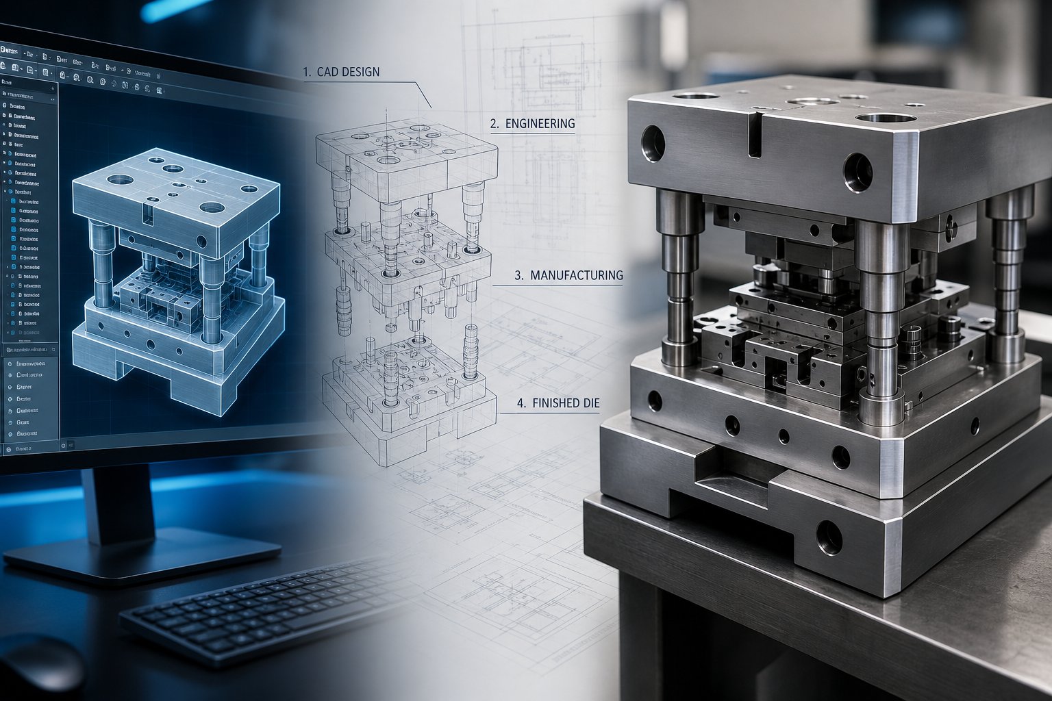
Material selection and process type are just two pieces of the puzzle. What often catches buyers off guard is the number of engineering stages between submitting a part drawing and receiving production components. A typical stamping die factory follows a structured sequence of steps, each one building on the last, to ensure your tooling performs flawlessly at full speed. Skipping or rushing any stage usually means rework, delays, or scrap down the line.
Here is the end-to-end workflow most die stamping projects follow:
- Feasibility Review - Initial assessment of part geometry, tolerances, volume requirements, and material choice.
- Design for Manufacturability (DFM) - Engineering team recommends modifications to simplify forming, reduce tool stations, or eliminate secondary operations.
- CAE Simulation - Finite element analysis models metal flow, predicts thinning, and identifies potential cracking or wrinkling before any steel is cut.
- Die Design - Detailed 3D CAD modeling of die components: punches, die blocks, strippers, guide systems, and material progression.
- Tool Steel Machining - CNC milling, grinding, and wire EDM shape hardened steel into precision die components.
- Die Assembly - All components are fitted, aligned using guide pins and bushings, and tested for clearance.
- Trial Runs - The die is mounted in the press and run at reduced speed to produce sample parts for evaluation.
- First Article Inspection (FAI) - Detailed dimensional verification confirms the first production part meets all drawing specifications.
- Production Approval - Customer reviews FAI data and signs off for full-rate manufacturing.
- Ongoing Production - Full-speed stamping begins with statistical process control monitoring quality in real time.
From Concept to Feasibility Review
The process starts when you submit your part drawing or 3D model. Engineers at the metal stamping dies manufacturer evaluate whether the geometry is achievable within your stated tolerance, volume, and material parameters. They look for features that might be problematic: extremely tight radii, deep draws relative to material thickness, or features that would require excessive stations in a progressive die.
DFM feedback typically follows within days. Imagine you have designed a bracket with a 90-degree flange that includes a hole punched too close to the bend line. The engineering team flags this and proposes relocating the hole or adjusting the flange radius, saving you weeks of tooling rework later. CAE simulation then validates these changes digitally, modeling how the metal flows under press force and predicting issues like springback or material thinning before any physical tooling exists.
Die Design, Machining, and Assembly
With simulation data confirming the forming strategy, die designers build detailed 3D models of every component. A progressive die manufacturer, for instance, maps out each station along the strip layout: where blanking occurs, where forms are made, and where the finished part separates from the carrier strip.
Tooling fabrication brings those models to life. Custom dies are machined using CNC milling, precision grinding, and wire EDM from high-quality materials such as hardened steel or tungsten carbide to withstand the repeated pressures of production stamping. Assembly involves fitting punches into retainers, aligning die shoes with guide pins and bushings, and verifying clearances at every station. This phase typically represents the longest lead time in the project, often ranging from six to twelve weeks depending on complexity.
Trial Runs, Inspection, and Production Launch
Trial runs are where theory meets reality. The assembled die is mounted in the press, and operators run it at reduced speed to produce initial samples. Engineers check for proper strip feeding, balanced forming forces, and clean shearing edges. Adjustments to punch height, timing, or lubrication happen here rather than during full production.
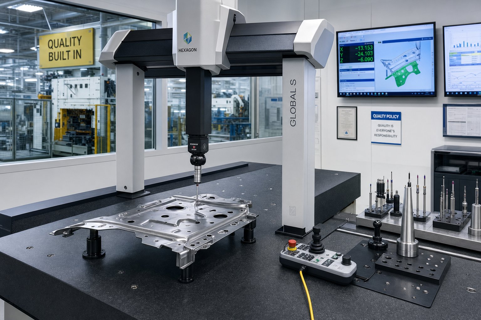
First Article Inspection is the formal gate between tryout and production. Inspectors measure critical dimensions using CMMs, calipers, or laser scanners, then document results against ballooned drawings. FAI catches issues like incorrect bend angles or hole misalignment before hundreds of thousands of parts are produced. It is especially important when launching a new part, changing tooling, or using new materials.
Once you review and approve the FAI report, production begins at full press speed. Statistical process control monitors dimensional consistency in real time, and periodic inspections ensure the die maintains its accuracy across the production run.
Companies like YICHEN structure their workflow to guide buyers through each of these stages, from feasibility and CAE simulation through machining, trial runs, and inspection, giving sourcing teams clear visibility into timelines and costs at every milestone.
Each of these workflow stages adds time and cost to your project, and understanding where those dollars go is essential for making informed budgeting decisions before you commit to tooling.
Certifications and Quality Control in Die Stamping
Workflow stages tell you how a part gets made. Certifications tell you whether you can trust the results. When you are evaluating any stamping dies manufacturer, the certifications they hold reveal far more than a logo on their website. They represent audited systems, documented processes, and a commitment to consistent output that has been independently verified.
What Each Industry Certification Means for Buyers
Not all quality certifications are created equal. Each one targets a specific industry's regulatory environment and carries its own operational requirements. Here is how the major certifications stack up for buyers sourcing stamped components:
| Certification | Industry Focus | Key Requirements | Why It Matters to Buyers |
|---|---|---|---|
| ISO 9001:2015 | General manufacturing (all industries) | Documented QMS, process-oriented structure, risk-based thinking, customer feedback mechanisms, internal audits | Establishes baseline quality discipline; confirms the supplier operates a structured, repeatable system |
| IATF 16949 | Automotive | PPAP documentation, APQP planning, FMEA analysis, measurement system analysis, customer-specific requirements | Mandatory for Tier 1 and Tier 2 automotive suppliers; ensures parts meet OEM specifications across millions of cycles |
| AS9100 | Aerospace and defense | Configuration management, first article inspection per AS9102, traceability to material heat lots, risk management, counterfeit part prevention | Confirms the supplier can handle flight-critical tolerances and full material genealogy |
| ISO 13485 | Medical devices | Design controls with verification and validation, biocompatibility documentation, contamination control, complaint handling, post-market surveillance systems | Required for regulated medical markets globally; emphasizes patient safety and regulatory compliance over continuous improvement alone |
A die metal stamping manufacturer holding IATF 16949 has already proven they can manage production part approval processes, control measurement systems, and respond to customer-specific requirements. That same supplier looking to serve medical device buyers would need to layer ISO 13485 on top, adding prescriptive documentation, longer record retention, contamination controls, and formal adverse event reporting to their existing systems.
What does this mean practically? When you see a certification listed, you are not just looking at a plaque on the wall. You are looking at evidence that the supplier undergoes regular third-party audits, maintains calibrated equipment on documented schedules, traces every material lot through production, and operates corrective action systems that close the loop on defects before they reach your assembly line.
Quality Control Methods and Inspection Processes
Certifications define the management system. Quality control methods define how that system operates on the shop floor. A precision die & stamping inc operation typically deploys multiple inspection layers to catch variation before it becomes a defect:
- Incoming Material Certification - Verifying raw material grade, temper, hardness, and coating thickness against purchase specifications before the strip ever enters a press.
- First Article Inspection (FAI) - Comprehensive dimensional verification of the first parts from a new tool or production batch, measured against the CAD model using CMM, calipers, and micrometers. This is the formal gate between tryout and production approval.
- Statistical Process Control (SPC) - Continuously monitoring key part dimensions during a production run, plotting data points on control charts to detect trends signaling tool wear or press drift before out-of-tolerance parts are produced.
- CMM Coordinate Measurement - Programmable probing of complex geometries, verifying features like hole true position, profile tolerances, and angular relationships that hand tools cannot reliably measure.
- Optical and Automated Inspection - Vision systems and automated optical inspection (AOI) provide objective, high-speed surface flaw detection for scratches, burrs, and tool marks, eliminating the subjectivity of manual visual checks.
- Destructive Testing - Periodic verification of mechanical properties through hardness testing (Rockwell or Vickers methods), tensile pull tests, and cross-sectioning to confirm material integrity after forming and any subsequent heat treatment.
The key principle here is that quality is built into the production sequence rather than inspected for afterward. SPC detects drift in real time. CMM validates geometry at defined intervals. Destructive testing confirms mechanical performance matches specification. Together, these methods create a closed-loop system where variation is identified and corrected before it compounds into scrap or field failures.
Understanding Achievable Tolerances
Tolerances vary depending on material, geometry, and the level of process control applied. Here is a general framework for what buyers can expect from precision die stamping operations:
- General commercial tolerances - Typically +/-0.1 mm to +/-0.25 mm for dimensional features like hole diameters, flange widths, and overall lengths. Suitable for brackets, enclosures, and non-critical assemblies.
- Close tolerances - Achievable in the range of +/-0.025 mm to +/-0.05 mm for critical features. Requires tighter tool construction, controlled material properties, and more frequent SPC sampling. Common in connector pins, aerospace structural parts, and medical device components.
- Flatness and form tolerances - Stamped parts can hold flatness within 0.05 mm per 25 mm of span when tooling is designed with coining or leveling stations. Parts requiring seal surfaces or flush mounting benefit from these additional forming operations.
Automotive applications typically specify tolerances in the +/-0.1 mm to +/-0.25 mm range for weld fixture alignment, while aerospace and medical components push toward the tighter end of the spectrum. The tighter you specify, the more process control, inspection frequency, and tooling precision are required, all of which influence project cost.
Certifications and quality systems give you confidence that your supplier can hold those tolerances consistently. But tolerances, inspection protocols, and tooling complexity all feed directly into the economics of your project, which raises a practical question: what actually drives the price of a die stamping program?
Cost Factors That Drive Die Stamping Project Pricing
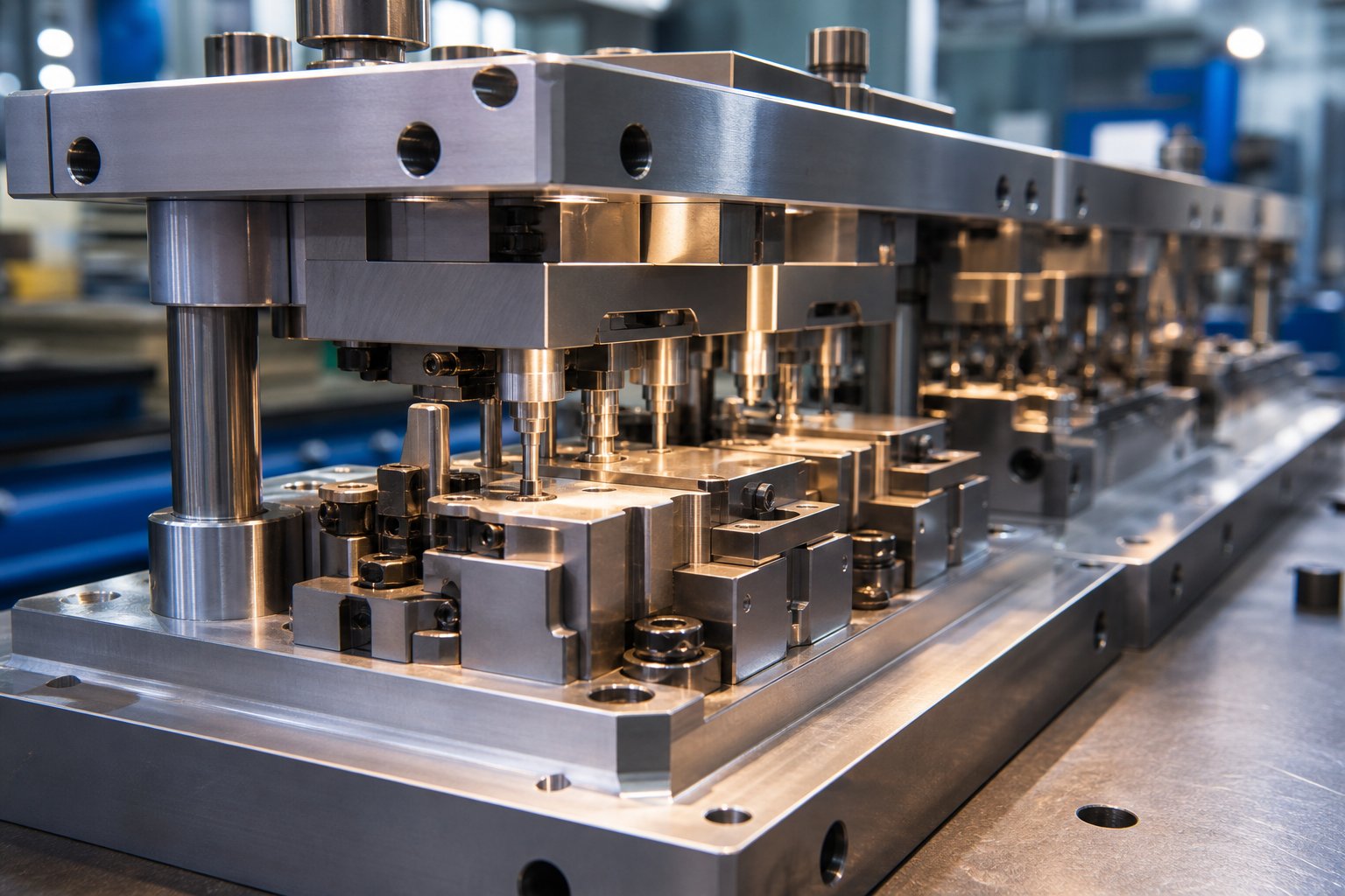
You get two quotes for what appears to be the same stamped bracket. One comes back at $0.50 per piece, the other at $5.00. Neither supplier is wrong. The gap reflects different assumptions about tooling complexity, volume, material grade, and secondary operations, each pulling the final number in a different direction. Understanding these cost drivers lets you make smarter tradeoffs instead of simply chasing the lowest quote.
Here are the primary factors that shape pricing at any die stamping company:
- Tooling investment - Die complexity, number of stations, tool steel grade, and expected tool life. A simple blanking die might cost $5,000, while a complex progressive die with multiple forming stations can exceed $100,000. Most projects land in the $15,000 to $50,000 range for moderate complexity.
- Material costs - Alloy choice, scrap rate, and nesting efficiency. Carbon steel sits at the low end; stainless, copper alloys, and specialty metals carry progressively higher premiums. Poor strip layout design wastes material that goes straight to the scrap bin.
- Production volume - Fixed tooling costs amortized over part count. Higher volumes spread that investment thinner, driving per-piece price down dramatically.
- Secondary operations - Deburring, heat treatment, plating, tapping, and hardware insertion all add handling time and cost beyond the die stamping press itself.
- Part complexity - Tight tolerances, intricate cutouts, deep forms, and multi-slide features each add stations to your die or require slower press speeds, increasing both tooling and production expense.
Tooling Investment and Die Complexity Costs
Tooling is almost always the single largest upfront expense. Every hole, bend, emboss, and cutout translates into an additional station or a more complex die geometry. A progressive die with twelve stations costs substantially more to design and machine than one with four stations, but it also eliminates downstream handling by completing all operations in a single pass through the press.
Tool steel grade matters too. Standard D2 or A2 die steels handle most production volumes, but stamping abrasive stainless alloys or running multi-million-piece programs may call for carbide inserts or premium grades like M2 high-speed steel. These upgrades extend tool life and reduce maintenance frequency, but they raise the initial investment. The decision comes down to lifetime economics: a more expensive die that runs two million hits before resharpening can cost less per part than a cheaper die needing service every 200,000 cycles.
Payment structures typically follow a 50/50 split, with half due at tooling order and the balance after sample approval. Stamping press suppliers and toolmakers structure it this way to cover machining costs while giving buyers a quality gate before final payment.
Production Volume and Per-Part Economics
Volume is the great equalizer in stamping economics. Imagine a $30,000 progressive die producing 10,000 parts. That is $3.00 per piece in tooling amortization alone. Scale to 300,000 parts and it drops to $0.10. The raw material and press time stay roughly constant per unit, so volume leverage comes almost entirely from spreading fixed costs.
This math explains why stamping becomes cost-competitive against laser cutting or CNC machining at volumes typically exceeding 10,000 parts per month. Below that threshold, alternative processes avoid the heavy tooling investment. Above it, the per-part economics of a die stamping press running at hundreds of strokes per minute are difficult to beat.
Blanket orders amplify the advantage further. Annual volume commitments let suppliers plan production scheduling, purchase material in bulk, and reduce administrative overhead. In return, buyers unlock better pricing and more predictable lead times. The tradeoff is forecasting accuracy: overcommitting ties up capital in inventory, while undercommitting leaves savings on the table.
Strategies to Reduce Die Stamping Project Costs
Cost optimization starts well before the first press stroke. The most effective lever is design for manufacturability. Simple geometry changes, like using standard bend radii, positioning holes at least 1.5 times material thickness from bends, and maintaining consistent wall sections, can eliminate tooling stations and reduce scrap rates without compromising function.
Other practical strategies include:
- Material substitution - Switching from stainless steel to a coated carbon steel where corrosion requirements allow can cut material cost significantly while simplifying die design.
- Consolidating secondary operations - Integrating in-die tapping or PEM fastener insertion raises upfront tooling cost but drops per-piece pricing by eliminating separate handling and division stamping of operations across multiple workstations.
- Optimizing strip layout - Better nesting of parts on the coil minimizes scrap. Smart progressive die design squeezes maximum value from every inch of material.
- Multi-year agreements - Longer commitments provide pricing stability and let suppliers invest in optimized tooling knowing the volume justifies it.
- Early supplier engagement - Bringing your stamping partner into the design phase gives them the opportunity to suggest changes that reduce complexity before tooling is committed.
The underlying principle is straightforward: every decision you make during design and sourcing ripples through the cost structure. A part geometry that looks good on a CAD screen might demand expensive tooling, while a minor radius change or hole relocation could save thousands in die construction and improve long-term production efficiency.
Cost awareness alone does not guarantee a good outcome, though. The same part priced identically can perform very differently depending on the industry it serves, the certifications required, and the documentation expected at delivery. Automotive, aerospace, electronics, and medical applications each layer their own demands on top of base stamping economics.
Industry Applications and What Each Demands
A bracket destined for a minivan door panel and a shielding can inside a surgical robot may both start as flat sheet metal, but the standards, documentation, and process controls surrounding each are worlds apart. Your industry dictates far more than material choice. It defines which certifications your supplier must hold, what inspection documentation ships with every lot, and how tight the tolerances need to be held across the entire production run.
Automotive Die Stamping Requirements
Automotive programs run on volume. Annual quantities in the hundreds of thousands or millions are routine, and every part must meet OEM specifications across that entire lifespan. IATF 16949 certification is effectively mandatory for Tier 1 and Tier 2 suppliers, requiring formal PPAP documentation, APQP planning, and measurement system analysis before a single production part ships.
You will also encounter customer-specific requirements layered on top. Each OEM adds unique packaging standards, labeling protocols, and engineering change management procedures. Tolerances typically land in the +/-0.1 mm to +/-0.25 mm range for stamped brackets, clips, and structural reinforcements. Regional suppliers across the Great Lakes metal stamping corridor, for example, have built deep expertise in these automotive workflows because proximity to Detroit's OEMs demands it.
Aerospace and Defense Considerations
Aerospace raises the bar on precision and traceability. Tolerances routinely tighten to +/-0.001 inches, and every stamped component must trace back to its specific material heat lot. AS9100 certification governs configuration management, counterfeit part prevention, and first article inspection per AS9102 protocols.
Material selection also shifts dramatically. Aerospace programs frequently specify titanium, Inconel, and specialized aluminum alloys that offer superior strength-to-weight performance but pose unique forming challenges including cracking, galling, and aggressive springback. Tooling for these alloys often requires specialized die coatings and carefully calculated press tonnage to maintain material integrity. Volumes tend to be lower than automotive, ranging from a few thousand to tens of thousands of pieces, but the documentation and inspection burden per part is substantially higher.
Electronics, Medical, and General Industrial Needs
Electronics stamping operates at a different scale entirely. Components like EMI shielding cans, grounding clips, battery contacts, and connector bodies require material thicknesses ranging from 0.001 inches to 0.032 inches, with individual features sometimes just a hair-width or two across. Materials like phosphor bronze, beryllium copper, nickel silver, and MuMetal are common because they combine electrical conductivity with wear resistance. Parts often ship in tape-and-reel packaging for automated pick-and-place assembly onto circuit boards.
Medical device stamping layers ISO 13485 requirements over the manufacturing process. Biocompatible materials such as 316L stainless steel or titanium are standard, and contamination control can extend to cleanroom handling and specialized packaging. Documentation requirements emphasize design controls, validation records, and post-market surveillance, with record retention periods far exceeding those in other industries.
General industrial applications prioritize flexibility over regulatory complexity. Buyers in construction, HVAC, agriculture, and heavy equipment need cost-efficient production across a broad material and volume range. Industrial machine products manufacturers in regions like Oxford, MI and throughout the Midwest often serve these markets with versatile press capabilities and shorter lead times, since certification burdens are lighter and tolerance bands are more forgiving.
| Industry | Key Certification | Typical Volumes | Critical Specs | Common Materials |
|---|---|---|---|---|
| Automotive | IATF 16949 | 100K to millions annually | PPAP, +/-0.1 to +/-0.25 mm tolerances, OEM-specific requirements | Carbon steel, HSLA, aluminum, stainless steel |
| Aerospace & Defense | AS9100 | 1K to 50K annually | +/-0.025 mm tolerances, heat lot traceability, AS9102 FAI | Titanium, Inconel, aerospace aluminum alloys |
| Electronics | ISO 9001 (minimum) | 10K to millions annually | Microstamping capability, 0.001"-0.032" material, tape-and-reel packaging | Phosphor bronze, BeCu, nickel silver, copper, MuMetal |
| Medical Devices | ISO 13485 | 5K to 500K annually | Biocompatibility, contamination control, extended traceability | 316L stainless, titanium, cobalt-chrome |
| General Industrial | ISO 9001 | 5K to 500K annually | Cost efficiency, flexible volumes, shorter lead times | Carbon steel, aluminum, brass, stainless steel |
Each industry's unique demands create a filtering mechanism. A supplier well suited for high-volume automotive brackets may lack the traceability infrastructure for aerospace, while a microstamping specialist may not have the press tonnage for heavy-gauge industrial parts. Recognizing where your project falls on this spectrum is the first step toward narrowing your supplier shortlist, but knowing what to look for during the actual evaluation process is what separates a good sourcing decision from an expensive lesson.
How to Evaluate and Select the Right Die Stamping Partner
You have narrowed your shortlist to a handful of progressive die stampings suppliers. Their websites look professional, the certifications check out, and the quoted prices are in a similar range. So how do you separate a supplier who will deliver consistent quality for years from one who will leave you chasing late shipments and fielding customer complaints six months from now?
The difference rarely shows up in a price comparison. It lives in the details: how deep their engineering bench goes, how they communicate during the quoting phase, and whether their equipment actually matches your part requirements. Here is a practical framework sourcing managers and tooling engineers can use to evaluate candidates with confidence.
Technical Capability Checklist for Buyers
Technical fit is the non-negotiable starting point. A supplier might have impeccable quality systems, but if their presses cannot handle your part geometry or tonnage requirements, nothing else matters. When reviewing capabilities, verify these specifics:
- Press tonnage range - Does the supplier operate presses that match your material and gauge requirements? Stamping 0.060-inch stainless steel demands significantly more tonnage than forming 0.020-inch aluminum. Ask for the full tonnage range, not just the largest press on the floor.
- Bed size and shut height - Larger parts or complex progressive dies with many stations need adequate bed dimensions. If your die exceeds available bed size, the supplier cannot run it regardless of other qualifications.
- Press speed range - High-volume connector programs might need 400+ strokes per minute, while heavy-gauge structural parts run at 30-60 SPM. Confirm the supplier operates at speeds compatible with your volume and part complexity.
- In-house tooling capability - Suppliers who design and build dies internally control their own lead times and can make adjustments faster than those who outsource tooling to third parties. Look for CNC machining, wire EDM, and precision grinding under one roof.
- Secondary operations - Can they handle deburring, tapping, plating, welding, or assembly in-house? Each operation sent to a subcontractor introduces transit time, handling risk, and coordination complexity.
- Material handling and coil capacity - Verify they can handle your coil widths, weights, and material types. Coil-fed progressive operations need appropriate decoilers, straighteners, and feeders matched to your strip dimensions.
- Certifications matching your industry - As covered earlier, automotive demands IATF 16949, aerospace requires AS9100, and medical needs ISO 13485. A precision die and stamping inc operation without the correct certification for your market is a non-starter, regardless of price.
Sounds like a lot of boxes to check? It is. But each one eliminates risk that would otherwise surface during production when the cost of switching suppliers is exponentially higher.
Evaluating Engineering Support and Communication
Technical specs on a capability sheet tell you what a supplier can do. Engineering support tells you how well they do it. The depth of a supplier's engineering team often determines whether your project launches on time or gets stuck in repeated tooling revisions.
When engaging potential partners, pay attention to these indicators:
DFM feedback quality. Submit your part drawing and evaluate how the supplier responds. Do they passively quote what you sent, or do they proactively identify potential forming issues, suggest radius changes, and flag tolerance callouts that will drive unnecessary tooling cost? A supplier who offers meaningful DFM recommendations during the quoting stage is demonstrating the same engineering discipline they will bring to your production program.
Simulation capability. CAE and finite element analysis are no longer optional for complex stampings. Ask whether the supplier runs forming simulations to validate die designs before machining begins. Simulation catches springback, thinning, and wrinkling digitally, saving weeks of physical tryout iterations. Suppliers like YICHEN integrate CAE simulation into their standard workflow from feasibility through trial runs, reducing the gap between theoretical die design and real-world press performance.
Prototyping options. For new product introductions, can the supplier produce prototype parts using soft tooling or single-station methods before committing to full production dies? This ability accelerates your design validation timeline without the risk of expensive rework on hardened progressive tooling.
Communication cadence. Research into buyer-supplier dynamics in metal stamping consistently highlights that predictability in communication matters as much as predictability in part quality. A supplier who goes silent during tooling build or fails to provide milestone updates is signaling how they will behave during production. Look for structured project management: defined milestones, regular status reports, and a single point of contact who owns your program.
Tooling ownership policies. This one catches buyers off guard. Who owns the die after it is paid for? Industry standard practice gives ownership to the buyer, but some suppliers retain tooling or charge transfer fees. Clarify ownership, maintenance responsibilities, and what happens to your die if you need to move production. Get it in writing during the quoting phase, not after a dispute arises.
RFQ Red Flags and Positive Indicators
The RFQ process itself is a diagnostic tool. How a supplier behaves when they are trying to win your business is the best version of how they will behave once they have it. Here is what to watch for:
Positive indicators:
- Detailed questions about your application, end-use environment, and assembly requirements rather than quoting strictly from the print
- Proactive DFM suggestions that reduce cost or improve quality
- Clear tooling lead time estimates with defined milestones
- Transparent pricing breakdowns separating tooling, piece price, and secondary operations
- References from customers in your industry that you can actually contact
- Willingness to provide trial-run data and sample parts before committing to production volumes
- Financial stability indicators: years in business, facility investment, diversified customer base
Red flags:
- Quotes returned without any technical questions asked, a sign the supplier is guessing rather than engineering
- Vague or missing lead time commitments
- Reluctance to share facility tour access or provide customer references
- Pricing dramatically below all other quotes with no clear explanation of how costs are reduced
- No mention of inspection methods, SPC, or quality documentation in the proposal
- Unwillingness to define tooling ownership terms upfront
- High employee turnover or frequent changes in your point of contact during the quoting phase
Geographic considerations also factor in, particularly for programs requiring frequent collaboration during die development. A supplier located within driving distance enables hands-on tryout participation, faster engineering changes, and reduced shipping costs for sample approval cycles. That said, geography should not override capability. A distant supplier with deep expertise in your specific application may outperform a local shop that lacks relevant experience.
Financial stability deserves scrutiny too. Longstanding relationships with material vendors and decades of continuous operation indicate resilience through market cycles. A supplier who has weathered downturns without compromising investment in equipment or personnel is far less likely to create supply disruptions mid-program than one operating on thin margins with aging machinery.
Ultimately, the evaluation framework boils down to a single question: does this supplier demonstrate the technical capability, engineering depth, and communication discipline to be a true manufacturing partner rather than just a vendor filling purchase orders? The answer usually becomes clear well before you issue the first PO, if you know what to look for during the RFQ conversation.
Making Confident Die Stamping Sourcing Decisions
Every section of this guide points toward the same underlying truth: successful stamping programs are built on informed decisions made early, not reactive fixes applied late. Whether you are sourcing a high-volume automotive bracket or a micro-tolerance aerospace connector, the principles that separate smooth launches from costly delays remain consistent.
Key Takeaways for Sourcing Decisions
Here is what matters most when you are moving from research into active supplier engagement with a die stamping company:
- Match process type to part geometry and volume. Progressive dies serve high-volume, multi-feature parts. Transfer dies handle larger or deeper geometries. Compound and single-station methods fit simpler parts at lower quantities. Choosing the wrong method inflates tooling cost or limits production efficiency.
- Verify certifications for your specific industry. IATF 16949 for automotive, AS9100 for aerospace, ISO 13485 for medical. These are not optional extras. They represent audited systems that ensure traceability, documentation, and process control at the level your application demands.
- Understand the full workflow timeline. From feasibility review through die machining, trial runs, and first article inspection, a typical program takes weeks to months before production parts ship. Building that timeline into your project plan prevents last-minute pressure that leads to shortcuts.
- Evaluate engineering depth, not just press capacity. A supplier with strong DFM feedback, CAE simulation capability, and proactive communication during quoting will outperform a larger shop that passively manufactures whatever you hand them. Engineering collaboration catches problems digitally before they become expensive physical rework.
- Request trial-run data before committing to production volumes. First article inspection reports, SPC data from tryout runs, and sample parts give you objective evidence of capability. Any stamping die supplier confident in their process will provide this data without hesitation.
The best sourcing outcomes come from early collaboration between buyer engineering teams and stamping die manufacturers, not from selecting the lowest quote after designs are locked.
Next Steps to Move from Research to RFQ
You have the framework. Putting it into action means engaging potential partners before your design is finalized, not after. Early involvement gives a variety die and stamping supplier the opportunity to recommend material substitutions, suggest geometry changes that simplify tooling, and flag tolerance callouts that will drive unnecessary cost. Research consistently shows that this collaborative approach shortens development cycles, reduces prototype iterations, and creates a more predictable path to production.
When you are ready to issue RFQs, send your part drawing to multiple qualified stamping die manufacturers and compare not just pricing but the quality of their technical questions, DFM feedback, and proposed timelines. The supplier who asks the most thoughtful questions during quoting is typically the one who delivers the fewest surprises during production.
Look for a partner offering full-service support from feasibility analysis through production inspection, one who treats your program as an engineering collaboration rather than a transactional purchase order. That distinction, more than tonnage or geography, is what drives long-term manufacturing success.
Frequently Asked Questions About Die Stamping Companies
1. What is the difference between progressive die stamping and transfer die stamping?
Progressive die stamping feeds a continuous metal strip through multiple stations while the workpiece stays attached to a carrier strip, making it ideal for high-volume small-to-medium parts at hundreds of strokes per minute. Transfer die stamping separates the blank from the strip at the first station, then mechanical fingers move the free-standing piece between stations. This allows deeper draws, threading, and more complex three-dimensional forming for larger parts. Progressive tooling suits volumes above 100,000 pieces, while transfer dies typically serve 10,000 to 100,000 piece runs where part geometry exceeds progressive capabilities.
2. How much does tooling cost for a die stamping project?
Tooling costs vary widely based on die complexity, number of stations, and tool steel grade. A simple blanking die may cost around $5,000, while complex progressive dies with multiple forming stations can exceed $100,000. Most moderate-complexity projects fall in the $15,000 to $50,000 range. Factors that increase tooling cost include tighter tolerances, additional stations for extra features, premium tool steels for abrasive materials, and carbide inserts for extended production runs. Payment is typically structured as 50% at tooling order and 50% after sample approval.
3. What certifications should a die stamping company have?
The required certifications depend on your industry. ISO 9001 is the baseline for general manufacturing quality systems. Automotive programs require IATF 16949, which mandates PPAP documentation, APQP planning, and measurement system analysis. Aerospace and defense applications need AS9100, covering material traceability to heat lots, configuration management, and counterfeit part prevention. Medical device stamping requires ISO 13485, emphasizing biocompatibility documentation, contamination control, and post-market surveillance. Always verify that a supplier holds the specific certification your end-market demands before engaging them.
4. How long does it take to go from design to production with a die stamping company?
A typical die stamping program follows a structured workflow: feasibility review, DFM feedback, CAE simulation, die design, tool steel machining, die assembly, trial runs, first article inspection, and production approval. The tooling fabrication phase alone often takes six to twelve weeks depending on complexity. Adding feasibility review, simulation, and trial runs, most programs require three to five months from initial engagement to first production parts. Buyers who engage suppliers early during the design phase and incorporate DFM recommendations can shorten this timeline by reducing tooling revision cycles.
5. What materials can a die stamping company process?
Die stamping companies process a wide range of metals including carbon steel (1008 through 1095), HSLA steel, stainless steel (300 and 400 series), aluminum alloys (1100, 3003, 5052, 6061), copper, brass, phosphor bronze, and specialty alloys like Inconel and titanium. Material thickness typically ranges from 0.020 inches to 0.625 inches. Material properties such as tensile strength, ductility, hardness, and springback directly influence die design, press tonnage requirements, and tooling wear rates. Choosing the right alloy early in the design phase helps optimize both die construction costs and long-term production economics.


