


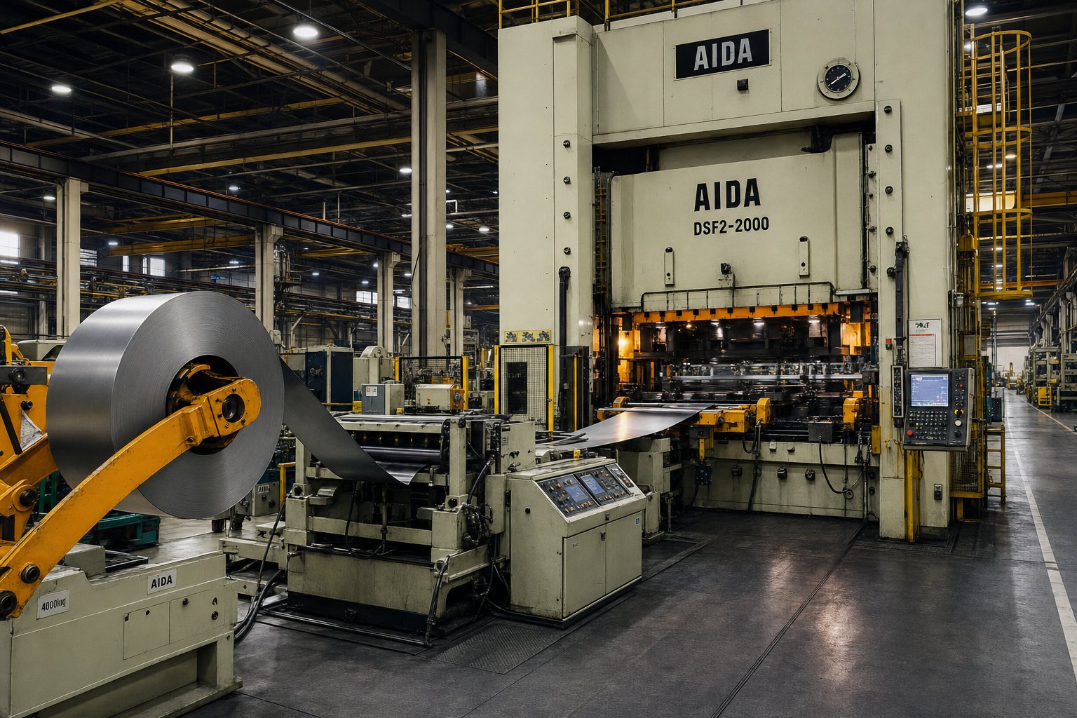
What Is a Progressive Die Stamping Factory
Imagine a facility where raw coils of metal enter one end and finished precision parts exit the other, all without a single hand touching the workpiece mid-process. That's the core idea behind a progressive die stamping factory, yet most buyers never see past the loading dock. This article takes you onto the factory floor to uncover what actually drives quality, cost, and delivery in these highly specialized operations.
Defining the Progressive Die Stamping Factory
A progressive die stamping factory is a manufacturing facility that integrates die engineering, high-speed press operations, and continuous coil-fed production under one roof to transform flat metal strip into finished components through sequential multi-station forming in a single press stroke cycle.
Here's what that means in practice. A metal coil feeds into a stamping press equipped with a progressive die, a specialized tool containing multiple stations arranged in sequence. With every stroke of the press, the strip advances a fixed distance and each station performs a different operation, whether that's piercing a hole, bending a tab, or coining a surface detail. All stations act simultaneously on different portions of the strip, so every press cycle produces a completed part at the final cutoff station. This process, often called prog die stamping on the shop floor, enables production rates that can reach hundreds or even thousands of parts per minute depending on complexity.
Progressive metal stamping relies on this multi-station principle to achieve tight dimensional repeatability across millions of cycles. Because the strip is guided by pilot pins and positioned by the die itself, each part comes out virtually identical to the last, making the method ideal for high-volume components requiring consistent quality.
How It Differs from General Metal Fabrication
A general metal fabrication shop and a progressive die stamping factory might both work with sheet metal, but the similarity ends there. Fabrication shops use standard equipment like laser cutters, press brakes, and welding stations to produce parts through separate, sequential operations. Each step often requires manual handling, repositioning, and individual setups. That flexibility makes fabrication excellent for prototypes, low-volume runs, and frequently revised designs.
A progressive die factory, by contrast, is built around dedicated tooling and continuous flow. The custom prog die combines every forming step into one integrated tool, eliminating manual transfers between machines. Where a fabrication shop might achieve tolerances of ±0.005" to ±0.015", progressive stamping routinely holds ±0.001" to ±0.005" with near-identical repeatability across entire production runs. The tradeoff is upfront tooling investment and reduced design flexibility once the die is built.
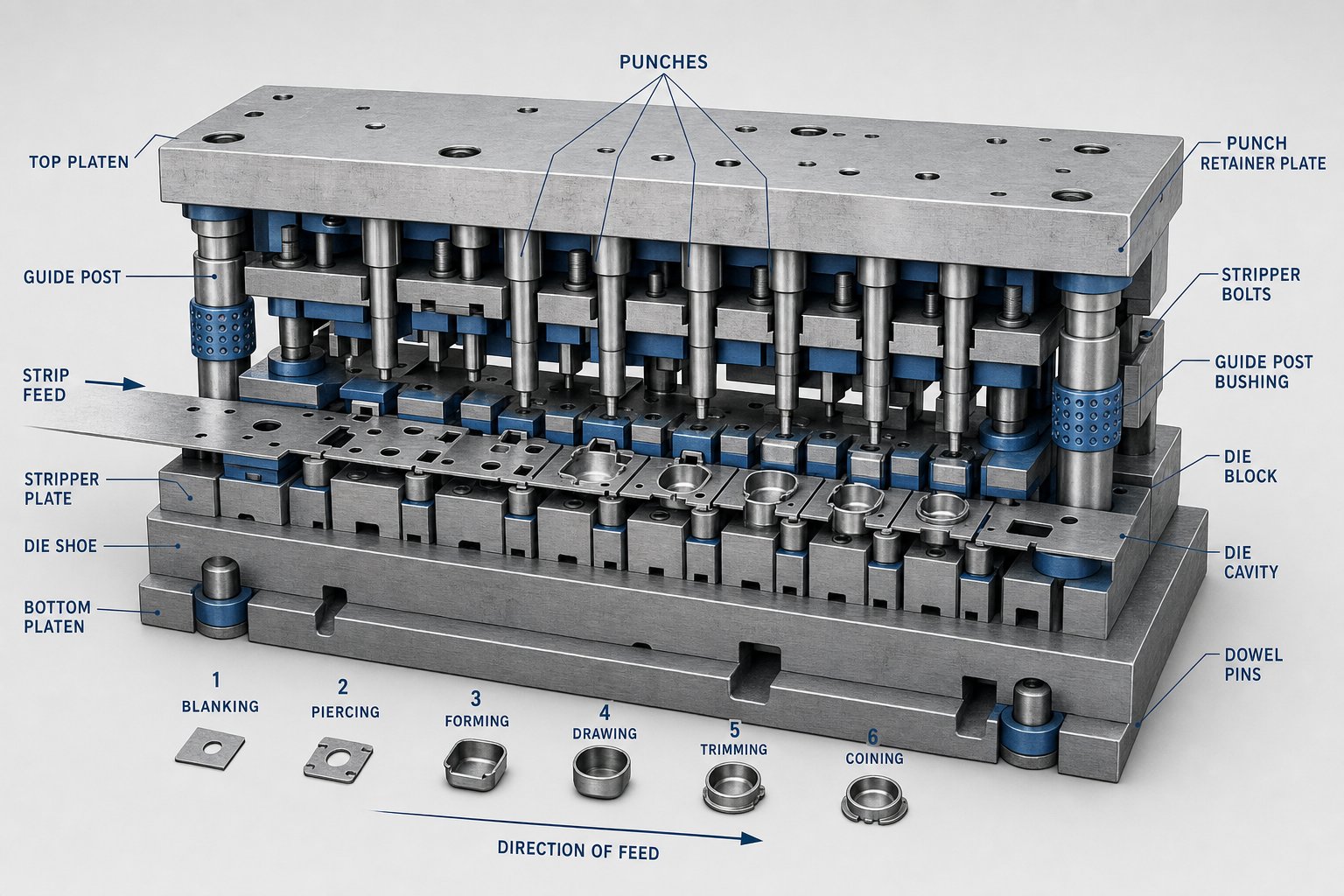
So what is a progressive die, exactly? It's a precision-engineered tool set containing punches, die blocks, stripper plates, pilots, and carrier systems, all designed to perform cutting and forming operations in a controlled sequence. The die itself is the heart of the factory, and its design determines everything from achievable tolerances to maximum press speed.
Understanding this distinction matters because it shapes every downstream decision, from material selection and die design to production volume thresholds and cost structures. The sections ahead break down each of these factors from the perspective of what actually happens inside these facilities, starting with the step-by-step mechanics of how a metal strip becomes a finished part.
How the Progressive Die Stamping Process Works
Strip goes in, finished parts come out. That one-sentence summary barely scratches the surface of what's actually happening inside the press. The progressive die stamping process is a tightly choreographed sequence where timing, precision, and material behavior all intersect within fractions of a second. Let's walk through each stage so you can visualize exactly how a flat coil transforms into a complex finished component.
From Coil to Finished Part in One Press Stroke
Picture a metal coil, sometimes weighing several thousand pounds, mounted on an uncoiler at the front of the press line. From there, the strip passes through straightening rollers that remove the natural curve left over from coiling, then advances into the die. Every stroke of the press drives the upper die half downward, and the strip moves forward by a fixed distance called the feed pitch. Here's the full progressive stamping process broken into its core steps:
- Coil loading - The metal coil is placed on an uncoiler and threaded into the line.
- Straightening - Rollers flatten the strip to eliminate coil set and ensure stable feeding.
- Lubrication - A thin film of stamping oil is applied to reduce friction and extend die life.
- Servo feeding - A precision feeder advances the strip by the exact feed pitch with each press stroke.
- Piloting - Pilot pins drop into pre-pierced holes to lock the strip's position before any forming begins.
- Station operations - Each die station performs its assigned cutting or forming task simultaneously on different sections of the strip.
- Carrier transport - The partially formed part stays connected to the carrier strip as it advances to the next station.
- Final cutoff - The last station separates the completed part from the carrier strip.
- Ejection and collection - Finished parts drop into bins, conveyors, or packaging systems below the die.
Every one of these steps happens within a single press stroke cycle. At production speed, the entire sequence can repeat hundreds of times per minute.
What Happens at Each Die Station
Think of a progressive stamping die as a series of specialized workstations arranged in a straight line inside a single tool. Each station handles one or two specific operations, and the strip encounters them in a carefully engineered order. A typical sequence might look like this:
- Piercing stations - Punch pilot holes and functional openings early in the strip. These pilot holes become the reference points for every subsequent operation.
- Blanking stations - Cut the outer profile or internal features that define the part's shape.
- Bending stations - Form tabs, flanges, or angles by pressing the material over shaped punches or die blocks.
- Forming stations - Create three-dimensional geometry, ribs, or embossed features that add structural rigidity.
- Coining stations - Apply high localized pressure to compress material for tighter dimensional control or surface detail.
- Cutoff station - Severs the finished part from the carrier strip, completing the cycle.
The order matters. Pilot and datum features are created first, heavy cutting loads are distributed across multiple stations to balance forces, and three-dimensional forming only happens after the strip has enough structural support to remain stable. Coining or calibration comes late in the sequence to correct any springback from earlier bends.
Why Simultaneous Multi-Station Operation Matters
Here's where progressive die metal stamping pulls ahead of other methods. During each press stroke, every station in the die is working at the same time, just on different portions of the strip. Station one pierces pilot holes on a fresh section while station four bends a tab on a section that entered four strokes earlier, and station eight cuts off a fully finished part that started its journey eight strokes ago.
This simultaneous operation means the cycle time for one part equals the cycle time for one press stroke, regardless of how many stations the die contains. A twelve-station die running at 200 strokes per minute still produces 200 finished parts per minute. Compare that to single-hit stamping, where each operation requires a separate press setup, manual part transfer, and individual cycle. Or consider transfer die stamping, which mechanically moves a detached blank between stations, adding handling time and limiting press speed.
The result is consistent repeatability across millions of cycles. Because the strip never leaves the die, every part follows the same path, encounters the same tooling geometry, and receives the same forming forces. Dimensional drift stays minimal as long as the die is properly maintained and the incoming material remains within specification. That level of process control is what makes this method the backbone of high-volume precision manufacturing, but achieving it depends heavily on choosing the right material for the die design, a factor that shapes everything from station count to achievable tolerance bands.
Materials That Shape Progressive Stamping Die Design and Performance
Every material tells the die designer what it wants to become and what it refuses to do. A strip of soft copper glides through forming stations with minimal resistance, while high-strength stainless steel fights back at every bend, demanding more tonnage, wider clearances, and additional stations to coax it into shape. The choice of progressive stamping materials doesn't just affect the finished part's performance. It dictates the entire die architecture from the first sketch to the last production stroke.
How Material Properties Drive Die Design Decisions
When you specify a metal for a progressive stamped part, you're simultaneously defining how the die must be built. Three mechanical properties carry the most influence:
- Tensile strength - Higher-strength metals require more press tonnage for cutting and forming. That translates to heavier tool steel components, thicker die plates, and potentially fewer operations per station to distribute load.
- Work-hardening rate (n value) - Materials that harden quickly during deformation, like austenitic stainless steels, distribute stretch more uniformly but also resist further forming at each successive station. Die designers must account for increasing forming forces as the strip progresses through stations.
- Thickness and ductility - Thicker stock needs larger punch-to-die clearances (typically 8-10% of material thickness per side) and longer forming legs. More ductile metals tolerate tighter bends and deeper draws without cracking, reducing station count.
These factors interact in ways that directly shape station layout. A part made from 0.030" mild steel might need eight stations, while the same geometry in 0.030" stainless steel could require ten or twelve stations to manage springback and work hardening. Each additional station adds die length, increases build cost, and demands a press with a larger bed.
Punch-to-die clearance is another critical variable. Optimal clearance controls burr height, cut-edge quality, and tool wear. Soft materials like aluminum can run tighter clearances for cleaner edges, while harder alloys need more room to prevent premature punch failure. Getting this wrong accelerates die wear and pushes parts out of tolerance faster than expected.
Common Metals and Their Stamping Characteristics
Sounds complex? It becomes more manageable when you understand the practical strengths and limitations of each material family commonly processed in a progressive die stamping factory. Here's how the most frequently specified metals compare:
| Material | Typical Applications | Formability Rating | Die Wear Impact | Achievable Tolerance Range |
|---|---|---|---|---|
| Mild / Carbon Steel (1008-1018) | Structural brackets, housings, automotive clips | High | Low to moderate | ±0.002" on pierced features |
| Stainless Steel (301, 304, 316) | Medical components, food equipment, corrosion-resistant hardware | Medium | High (abrasive to tooling) | ±0.0025" on pierced features |
| Copper (C110, C101) | Electrical contacts, bus bars, thermal conductors | High | Low (soft on tooling) | ±0.002" on pierced features |
| Brass (C260, C270) | Connectors, decorative hardware, valves | High | Low to moderate | ±0.002" on pierced features |
| Aluminum (3003, 5052, 6061) | Lightweight enclosures, heat sinks, HVAC fins | Very high | Moderate (galling risk) | ±0.002" on pierced features |
| High-Strength Steel (HSLA, DP) | Automotive structural reinforcements, safety components | Low | Very high | ±0.003" on pierced features |
Carbon steel progressive stamping remains the workhorse choice for structural parts because mild steel grades offer excellent formability at low cost. Their moderate tensile strength keeps press tonnage requirements reasonable, and their predictable behavior allows die designers to use standard clearances and conventional tool steels. When corrosion protection is needed, zinc or chromate plating adds durability without altering die design significantly.
Stainless steel progressive stamping introduces a different set of challenges. Austenitic grades like 304 work-harden aggressively, meaning each forming station encounters a progressively harder material. Designers respond by adding intermediate annealing stations or splitting complex forms across multiple hits. Stainless also wears cutting edges faster, often requiring carbide or coated punches rather than standard D2 tool steel.
Progressive stamping copper and brass is common for electrical components where conductivity matters more than raw strength. Copper's softness makes it forgiving during forming but creates its own headache: slugs tend to stick to punches, and the material can smear across die surfaces. Proper lubrication and polished punch faces help manage these tendencies. Brass offers more rigidity while retaining good formability, making it popular for connectors and terminals that need spring-like behavior.
Progressive stamping aluminum requires attention to galling, a condition where aluminum micro-welds to tool surfaces under pressure. Die designers counter this with specialized coatings like TiN or DLC on punches, along with heavier lubrication. Aluminum's very high formability and low weight make it attractive for HVAC fins, electronics enclosures, and automotive lightweighting applications, but the tooling demands are distinct from steel progressive stamping.
Matching material to application isn't just about what the part needs in service. It's about understanding how that choice ripples backward through die design, maintenance schedules, and production economics. A material that forms easily but destroys tooling quickly may cost more over a million-part run than a harder-to-form metal that preserves die life. This interplay between material behavior and factory infrastructure determines what equipment the operation needs to support efficient, repeatable production at scale.
Factory Infrastructure and Critical Equipment
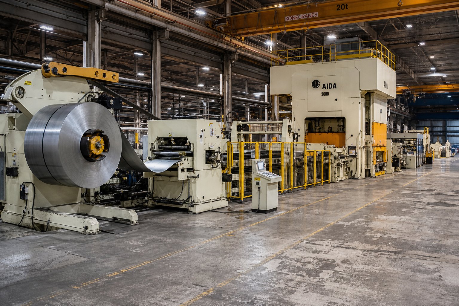
Material properties define what the die must accomplish, but it's the press line infrastructure that determines whether those demands can be met at speed, at volume, and within tolerance. Most buyers evaluate a progressive die stamping factory on part price alone. They rarely ask what's behind the quote: the press type, feed precision, coil handling capacity, or inspection systems that collectively separate a capable supplier from one running on borrowed time.
Press Types and Tonnage Selection
The progressive stamping press is the engine of the entire operation, and two primary technologies dominate the floor: mechanical and servo-driven.
A mechanical press stores rotational energy in a flywheel and releases it through a crankshaft to drive the ram downward. These machines excel at raw speed and simplicity, often running at higher strokes per minute than servo alternatives. Their fixed stroke profile makes them ideal for repetitive, high-volume progressive die tooling where the forming requirements stay consistent from the first part to the millionth. Mechanical presses also carry lower upfront costs and simpler maintenance requirements, keeping total cost of ownership manageable for operations that don't need mid-stroke programmability.
Servo-driven presses replace the flywheel mechanism with servo motors that directly control ram movement. The key advantage is programmability: operators can adjust slide speed, dwell time, and force at any point in the stroke. This flexibility matters when your progressive stamping tool encounters materials like stainless steel or high-strength alloys that benefit from slower forming speeds at bottom dead center. Servo presses also allow in-stroke pauses for feed systems or transfer operations, making them well-suited for complex part geometries. The tradeoff is reduced maximum speed and higher initial investment.
Tonnage selection ties directly to the material being processed. You need enough press capacity to handle the combined cutting and forming loads across all die stations simultaneously. A progressive die press running a twelve-station tool in 0.060" mild steel faces very different force requirements than the same station count in 0.040" stainless. Under-tonnage leads to incomplete forming and premature tool failure, while over-specifying wastes capital. Most factories maintain a range of presses, typically from 30 tons for miniature connector dies up through 600 tons or more for structural automotive components.
Feed Systems and Coil Handling Equipment
The press can only produce good parts if the strip arrives flat, straight, and positioned within thousandths of an inch on every stroke. That responsibility falls to the coil handling line, a system that works upstream of the die but directly determines what comes out the other end.
A complete coil press feed equipment line includes three integrated components:
- Coil reel (uncoiler) - Holds and unwinds the metal coil at a controlled rate. Motorized models are essential for heavier stock to maintain consistent tension and prevent surging.
- Straightener - Uses precision rollers to remove coil set, the residual curvature from being wound on a spool. Without proper straightening, the strip enters the die with built-in dimensional errors that compound through every forming station.
- Servo feeder - Advances the strip by the exact feed pitch required for each press stroke. Modern servo feeders achieve positioning accuracy down to ±0.0005", which is critical for maintaining pilot pin alignment and preventing misfeeds that can crash the die.
When these three systems work in sync, the strip enters the progressive stamping tool flat, stress-free, and precisely located. Any weakness in this chain, a worn straightener roller, a feeder with backlash, or an undersized uncoiler, shows up immediately as dimensional variation or die damage. Experienced buyers ask about feed system age, accuracy specs, and maintenance records for good reason.
In-Line Quality Inspection Technology
Speed means nothing if you're making scrap at 300 strokes per minute. That's why modern facilities integrate inspection directly into the press line rather than relying solely on post-production sampling.
- In-die sensors - Monitor tonnage, strip position, and part ejection in real time. A sudden tonnage spike signals a slug pull or misfeed before it escalates into a die crash.
- Vision inspection systems - High-speed cameras mounted at the die exit evaluate critical dimensions against a digital master on every single part. Inline AOI (Automated Optical Inspection) captures images at production speed, flagging dimensional deviations and removing defective parts without slowing the press.
- Laser measurement - Non-contact gauging of features like bend angles, heights, and hole positions for parts where camera-based inspection lacks the resolution.
- Part presence and ejection detection - Confirms that finished parts clear the die before the next stroke begins, preventing double-hits and tooling damage.
These systems create a closed feedback loop. Rather than discovering a tolerance drift after producing thousands of parts, the press line catches deviations within cycles and can trigger automatic shutdowns before scrap accumulates.
Some factories push integration even further by incorporating secondary operations directly into the press line. Tapping, welding, insert installation, selective plating, and even automated packaging can happen in-line, eliminating part handling between discrete workstations. This kind of integration reduces lead time, minimizes work-in-process inventory, and removes opportunities for handling damage, but it also demands more sophisticated press line controls and a higher level of engineering investment upfront.
All of this infrastructure carries cost, and that cost factors directly into the economics of every part that rolls off the line. Press tonnage, die complexity, feed precision, and inspection technology all contribute to the per-unit price, but not in the simple linear way most buyers assume. Understanding how tooling investment and production volume interact reveals why progressive die stamping dominates certain cost brackets while other methods win at different scales.
The Economics of Progressive Die Stamping
Infrastructure determines capability, but volume determines whether that capability makes financial sense for your project. The most common mistake buyers make when evaluating progressive die stampings isn't choosing the wrong factory. It's applying the wrong manufacturing method to their production scale, either paying for tooling they'll never amortize or overpaying per-part on a method that can't keep pace with demand.
The economics here aren't complicated, but they are counterintuitive. A higher upfront investment can deliver dramatically lower total program cost, but only when volume thresholds align with die complexity. Let's break down where those thresholds sit and what framework you should use to evaluate them.
When Progressive Die Tooling Investment Pays Off
Progressive die and stamping tooling carries a meaningful upfront cost. A simple four-to-six station die handling basic pierce-and-bend operations in mild steel typically falls between $10,000 and $25,000. Medium-complexity tooling with eight to fourteen stations, tighter tolerances, and forming operations lands in the $25,000 to $60,000 range, which is where the majority of automotive and electronics applications concentrate. Dies exceeding $60,000 usually involve deep drawing, in-die tapping, carbide inserts, or specialized sensing packages.
That investment only makes sense when per-part savings outweigh it within a reasonable payback window. Here's how different annual volumes typically align with manufacturing approaches:
| Annual Volume | Recommended Approach | Per-Part Economics |
|---|---|---|
| Under 10,000 | Laser cutting, turret punch, or single-hit dies | Higher per-part cost, minimal tooling investment |
| 10,000 to 50,000 | Single-station or simple compound dies | Moderate tooling ($3K-$15K), break-even depends on part complexity |
| 50,000 to 500,000 | Progressive dies become strongly favorable | Tooling amortizes rapidly, per-part cost drops 60-80% vs. discrete methods |
| Over 500,000 | Progressive dies essential; transfer dies for large or deep parts | Maximum efficiency, sub-penny per-part cost achievable |
The crossover point varies by part geometry, but 50,000 annual units represents the threshold where most applications justify progressive tooling investment. Below that volume, die cost divided by unit count overwhelms per-part savings. Above it, long run progressive stamping typically delivers payback within 6 to 18 months.
Consider a practical comparison. A mounting bracket costs $5.00 per unit through laser cutting with manual secondary operations. The same bracket costs $0.50 per unit through die stamping once tooling exists. At 50,000 annual units, progressive stamping saves $225,000 per year in part costs. A $35,000 die investment pays for itself in under two months of production. At 10,000 units, the same die takes over a year to break even, and at 5,000 units, it may never recover its cost during the product's lifecycle.
Part complexity pushes these thresholds higher. A twelve-station die with forming, coining, and in-die tapping costs significantly more than a six-station blank-and-bend tool. More stations mean more engineering hours, more precision grinding, and more iterative tryout cycles. If your geometry demands a $55,000 die, you'll need proportionally higher volumes or larger per-part savings to justify the investment. As a rule of thumb, each additional station adds $3,000 to $8,000 to the die build depending on complexity, and raises the break-even volume accordingly.
Total Cost of Ownership Beyond Per-Part Price
Most procurement teams calculate ROI by dividing die cost by per-part savings and deriving a payback period. This captures maybe half the picture. Total cost of ownership includes factors that don't appear on the initial quote but accumulate across the life of a production program:
- Die build cost - The quoted price, which typically covers design, materials, machining, and assembly. It rarely includes the iterative debugging that transforms a mechanical assembly into a stable production system. Medium-complexity progressive dies commonly require 5 to 8 tryout iterations before achieving conforming parts.
- Development and tryout - Engineering hours, press trials, component repairs after misfeeds, and measurement cycles. One industry analysis found that development costs approached the die cost itself for complex applications.
- Maintenance intervals - Cutting edges dull, forming surfaces wear, and spring components fatigue. Well-maintained progressive dies require sharpening every 50,000 to 200,000 strokes depending on material abrasiveness. Each maintenance cycle costs toolroom time and production downtime.
- Die life expectancy - A properly designed and maintained die can produce millions of parts before requiring major refurbishment. Class A tooling with replaceable inserts extends this lifespan significantly compared to one-piece construction.
- Scrap rate - Inherent material waste from the carrier strip and any parts rejected during production. Smart strip layout optimization minimizes skeleton waste, but every progressive die generates some unavoidable scrap. Material waste directly affects cost, and poor strip design can mean throwing money in the scrap bin.
There's also indirect value that simple payback math misses. Progressive die stampings free up press capacity that slower methods previously consumed. They reduce quality holds by eliminating manual handling between operations. They compress lead times because production runs start in minutes rather than requiring multi-hour setups across several machines. These indirect savings typically push the full ROI case 30-50% beyond what per-part calculations alone suggest.
The procurement discipline that saves money on commodity purchases, lowest compliant bid wins, fails when applied to progressive tooling. A die quoted at $22,000 that requires $15,000 in unplanned development and crashes twice in its first year costs more than a $38,000 die that runs clean from day one. Evaluating total cost of ownership rather than purchase price separates experienced buyers from those headed for budget overruns.
Yet even the best economic model only works if the die actually produces conforming parts over its intended lifespan. What keeps a million-stroke die from drifting out of tolerance, what causes catastrophic failures, and how well-run factories prevent both are questions that separate capable operations from ones running on borrowed time.
Failure Prevention and Quality Control on the Factory Floor
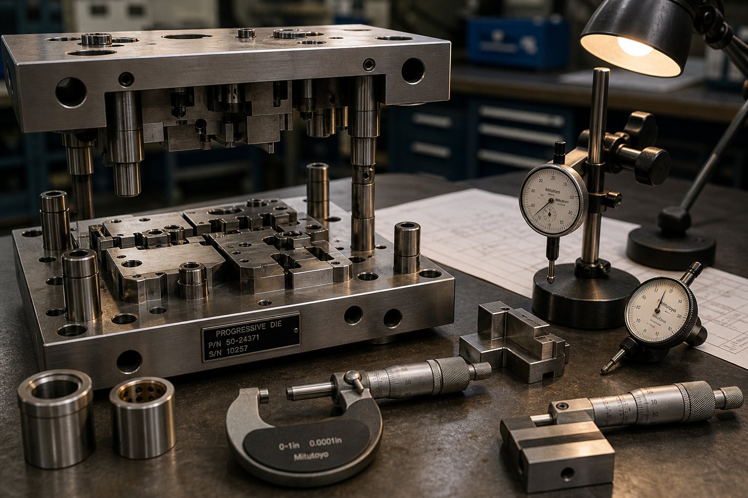
A progressive die doesn't fail all at once. It whispers before it screams. A burr grows a few thousandths taller each shift. A pilot hole drifts by half a thou over 50,000 strokes. A slug sticks to a punch face once, then twice, then jams between stations and crashes the die. The factories that avoid catastrophic failures aren't lucky. They've built systems that listen to those whispers and act before the damage compounds.
Common Failure Modes in Progressive Stamping
Progressive dies operate under repeated high-speed impact, and the failure patterns they develop are remarkably consistent across different applications. Understanding these patterns helps you evaluate whether a supplier is managing tooling proactively or just waiting for something to break.
- Slug pulling - During piercing, a small disc of material (the slug) is punched through the die opening. Normally it drops cleanly through a relief hole. But when vacuum pressure between the punch face and slug causes adhesion, the slug rides back up with the punch and gets trapped inside the die cavity. The next stroke drives it into the strip or die surface, potentially damaging both. Slug pulling accelerates as punch faces wear and lose their surface finish.
- Strip misfeeds - If the servo feeder releases the strip too early or too late, or if worn pilot pins fail to register the strip accurately, the material arrives out of position for the next press stroke. At best, this produces an out-of-tolerance part. At worst, the punch hits an unsupported area and the entire die crashes, bending or breaking hardened tool steel components that take days or weeks to replace.
- Burr formation - Every piercing and blanking punch gradually loses its cutting edge sharpness. As that edge rounds over, the material tears rather than shearing cleanly, producing a raised burr along the cut edge. Burr growth isn't just a cosmetic issue. Increased burr height raises stripping resistance, which in turn increases slug adhesion risk and feeds back into the slug pulling problem.
- Progressive wear patterns - Guide pins and bushings develop microscopic play. Stripper plates wear unevenly, creating inconsistent pressure across the strip. Forming inserts lose their profiles by thousandths of an inch per hundred thousand strokes. None of these individually cause immediate failure, but their cumulative effect gradually shifts dimensional characteristics across multiple stations simultaneously.
- Lubrication starvation - Even when the overall lubrication system appears functional, localized dry contact zones can develop around deep piercing stations or tight forming areas. Insufficient oil causes galling, heat buildup, surface pickup on punches, and accelerated guide wear, especially in narrow-pitch progressive stamping dies processing stainless steel.
These failure modes are highly interconnected. Punch wear leads to burr growth, which increases stripping force, which causes slug pulling, which damages the strip, which causes a misfeed. A single overlooked symptom can cascade into a full die crash within hours of high-speed production. That's why capable factories treat prevention as a system rather than a checklist of individual tasks.
Preventive Maintenance and Die Life Management
There's a meaningful distinction between die repair and die maintenance, and it reveals a lot about how a factory operates. As tooling expert Art Hedrick notes, if your daily activities revolve around fixing broken components and digging crashed parts out of the tool, that's repair. True preventive maintenance means sharpening cutting sections on schedule, replacing springs before they fatigue, inspecting for loose fasteners, and resurfacing wear components before they cause production problems.
Well-run factories manage progressive dies through stroke-count-based maintenance intervals rather than waiting for visible defects:
- Sharpening schedules - Cutting edges are reground at predetermined stroke counts, typically every 50,000 to 200,000 hits depending on material hardness. Waiting until burrs become visible means the tooling has already worn past optimal condition and stressed adjacent components.
- Component replacement triggers - Springs, pilot pins, guide bushings, and stripper bolts all have finite lifecycles. Tracking actual strokes against manufacturer-rated life allows replacement before failure. Progressive carbide stamping dies extend these intervals significantly in high-wear stations, since carbide inserts maintain dimensional stability far longer than conventional tool steel.
- Die life tracking - Every die gets a maintenance log tied to cumulative stroke count. This historical data reveals patterns: which stations wear fastest, which components fail first, and what intervals keep the tool producing conforming parts without unscheduled downtime.
- Cleaning and inspection protocols - Debris like slugs, slivers, and lubricant buildup accumulates inside the die during production. Regular cleaning prevents contamination from interfering with strip movement or forming surfaces. Inspections check for loose dowels, cracked inserts, galled surfaces, and worn guide components.
The grinding process itself demands attention. When sharpening hardened tool steel like D2 or M4, you're cutting through embedded carbide particles that resist conventional abrasives. Using the wrong grinding wheel causes heat buildup that can soften or crack cutting edges, creating a new failure point while trying to fix an old one. Flood coolant and properly friable wheels prevent thermal damage during sharpening.
Quality Systems That Catch Problems Early
Preventive maintenance handles known wear, but production variability introduces unknowns: incoming material that's slightly out of spec, ambient temperature shifts that alter die clearances, or a coil splice that changes strip tension mid-run. Catching these anomalies before they produce scrap requires real-time monitoring layered on top of scheduled maintenance.
- Tonnage monitoring with SPC - Every press stroke generates a measurable load signature. Load monitors capture peak tonnage on each cycle and express the data as X-bar and sigma control charts. When tonnage drifts outside statistical control limits (typically set at +/-3 standard deviations from the mean), the press stops automatically. A tonnage spike often indicates a slug pull or misfeed; a gradual increase signals progressive edge wear or lubrication breakdown.
- Strip tracking and feed validation - Sensors confirm that the strip has advanced the correct distance before allowing the next stroke. Misfeeds caught at this stage trigger an immediate stop, preventing die-on-die contact that would otherwise destroy hardened components.
- In-die sensing - Proximity sensors, part-out detectors, and buckle sensors monitor specific conditions inside the die during each cycle. A part that doesn't eject, a strip that buckles between stations, or a forming operation that doesn't reach full depth all generate alarms before producing cascading damage.
- Pareto analysis of downtime causes - Tracking why the press stopped, and ranking those causes by frequency, reveals systemic issues rather than random events. If tonnage alarms concentrate around a specific station, that station likely needs design reinforcement rather than repeated sharpening.
Statistical process control transforms raw tonnage data into actionable intelligence. Rather than reacting to the most recent alarm, operators and toolroom teams use trend data to predict when maintenance is needed and identify root causes that repeat across production runs. This approach treats each progressive die as a system with measurable performance characteristics rather than a static tool that either works or doesn't.
Factories operating at this level of discipline don't just prevent failures. They generate the documentation and process data that downstream buyers increasingly require: proof that parts were produced under statistical control, traceability records linking specific die conditions to specific production lots, and capability studies demonstrating repeatable performance over extended runs. That documentation matters even more when you're evaluating potential suppliers, because the quality systems behind the parts tell you far more about long-term reliability than a sample inspection ever could.
How to Evaluate a Progressive Die Stamping Factory
Quality systems generate data. Data proves capability. But capability only matters if the factory you're evaluating actually matches your production requirements in the first place. Too many procurement teams shortlist progressive die manufacturers based on price alone, only to discover months later that the supplier's press range can't handle their part tonnage, or that the quality certifications on the website don't cover stamping operations at all. A structured evaluation framework prevents those expensive lessons.
Certifications and Quality System Indicators
Certifications tell you what level of process discipline a progressive stamping company maintains, and which industries it's qualified to serve. But not all certifications carry equal weight, and the details inside them matter more than the logos on a supplier's homepage.
- ISO 9001:2015 - The baseline. Any reputable progressive die manufacturer should hold this as a minimum. It confirms documented processes, calibration schedules, internal audits, and corrective action systems. However, ISO 9001 alone does not require statistical process control, FMEA, or PPAP, which limits its rigor for high-volume precision applications.
- IATF 16949:2016 - Required for automotive OEM supply chains. This standard incorporates all ISO 9001 requirements plus mandatory APQP, PPAP, SPC, and error-proofing. IATF-certified suppliers face unannounced audits and must demonstrate process capability (Cpk ≥ 1.33) on critical dimensions. If your parts serve automotive applications, this certification is non-negotiable.
- ISO 13485 - Specific to medical device manufacturing. Requires design controls, biocompatibility documentation, and full lot traceability.
- AS9100 - Aerospace standard demanding zero-defect culture, materials traceability, and first-article inspection protocols.
Here's the catch: always verify that the certification scope explicitly covers metal stamping processes at the site where your parts will be produced. A company might hold IATF 16949 for assembly operations at one facility while running uncertified stamping at another. Request the actual certificate, confirm the site address, and check the IATF global oversight database for automotive suppliers.
Assessing Engineering and DFM Capabilities
The most telling indicator of a progressive die stamping services provider's long-term value isn't what happens during production. It's what happens before the die is ever built. Design for Manufacturability collaboration at the quoting stage directly determines how many tryout iterations the tooling will require, and engineering decisions made early in this phase dictate up to 80% of total production cost.
When you engage a supplier that offers genuine DFM partnership, you'll notice feedback like: "Move this hole two material thicknesses from the bend to prevent distortion," or "Adding one forming station here eliminates a secondary operation that saves $0.12 per part at your volumes." That kind of input requires experienced die designers who understand material behavior, not just CAD operators redrawing your geometry.
Look for these engineering capability markers:
- FEA and forming simulation - Suppliers using Finite Element Analysis predict springback, thinning, and cracking risk before cutting steel, eliminating the costly build-test-fix cycle.
- In-house die build and tryout - Facilities that design, machine, assemble, and validate dies internally can iterate faster than those outsourcing toolroom work.
- Strip layout optimization - Experienced engineers minimize material waste while maintaining stable carrier strip geometry, directly reducing per-part cost.
Suppliers like YICHEN support production engineers and procurement teams in sourcing progressive stamping dies for high-volume metal parts, offering early-stage engineering partnership focused on efficient multi-station forming, tight repeatability, and scalable mass production. This type of collaborative approach, where die design feedback starts at the RFQ stage rather than after tooling issues appear, is exactly what separates a strategic partner from a transactional vendor.
Equipment and Workforce Evaluation Criteria
Certifications confirm systems. Engineering capability confirms intelligence. But equipment condition confirms whether the factory can actually execute at the tolerances and volumes your project demands. Here's a structured comparison of what to evaluate, why it matters, and what should raise concerns:
| Evaluation Criteria | What to Look For | Why It Matters | Red Flags |
|---|---|---|---|
| Press range and tonnage | Multiple presses spanning 30-600+ tons; servo and mechanical options | Ensures your part's material and geometry can be processed without over- or under-loading equipment | Single press size only; no servo capability for complex forming |
| Maximum strip width capacity | Feed lines accommodating your part's strip width plus carrier and scrap allowances | Undersized feed equipment limits part geometry or forces suboptimal strip layouts | Feed line maxes out near your strip width with no margin |
| Equipment age and maintenance records | Documented PM schedules, rebuild history, and ram parallelism checks within the past 12 months | Worn presses lose alignment, directly degrading part tolerances and accelerating die wear | No maintenance logs available; visible oil leaks or excessive noise during operation |
| Workforce expertise | Dedicated die designers, experienced tool and die makers, press operators with 5+ years in progressive stamping | Skilled teams diagnose problems faster, reduce tryout iterations, and maintain tighter process control | High turnover; operators managing multiple unrelated processes; no in-house toolroom |
| Quality management systems | SPC software, real-time tonnage monitoring, CMM inspection, documented control plans per part number | Proves the factory detects and prevents drift rather than relying on post-production sorting | Inspection limited to calipers and go/no-go gauges; no statistical data available for review |
| Secondary operations integration | In-line tapping, hardware insertion, plating coordination, or sub-assembly capability | Reduces supply chain complexity and handling damage between vendors | All secondary work outsourced with no quality oversight of sub-tier suppliers |
When visiting a facility, pay attention to what you see between the presses. Organized tool storage with labeled racks, clean die maintenance areas, and visible tracking boards for active jobs signal a disciplined operation. A toolroom cluttered with in-progress repairs and no visible scheduling system tells you maintenance is reactive rather than planned.
The workforce question is often overlooked. Progressive die manufacturers depend on institutional knowledge that takes years to develop. Ask how long the senior die designers and toolmakers have been with the company. High retention in the toolroom usually correlates with stable production quality, because the people maintaining your die understand its history and quirks better than any documentation alone can capture.
Evaluating a supplier against these criteria gives you a framework that goes beyond sample parts and quoted prices. It tells you whether the operation can sustain quality at volume over years of production, not just deliver a clean first article. That sustained capability matters differently depending on which industry you're sourcing for, because automotive, medical, electronics, and aerospace each layer their own requirements on top of this baseline.
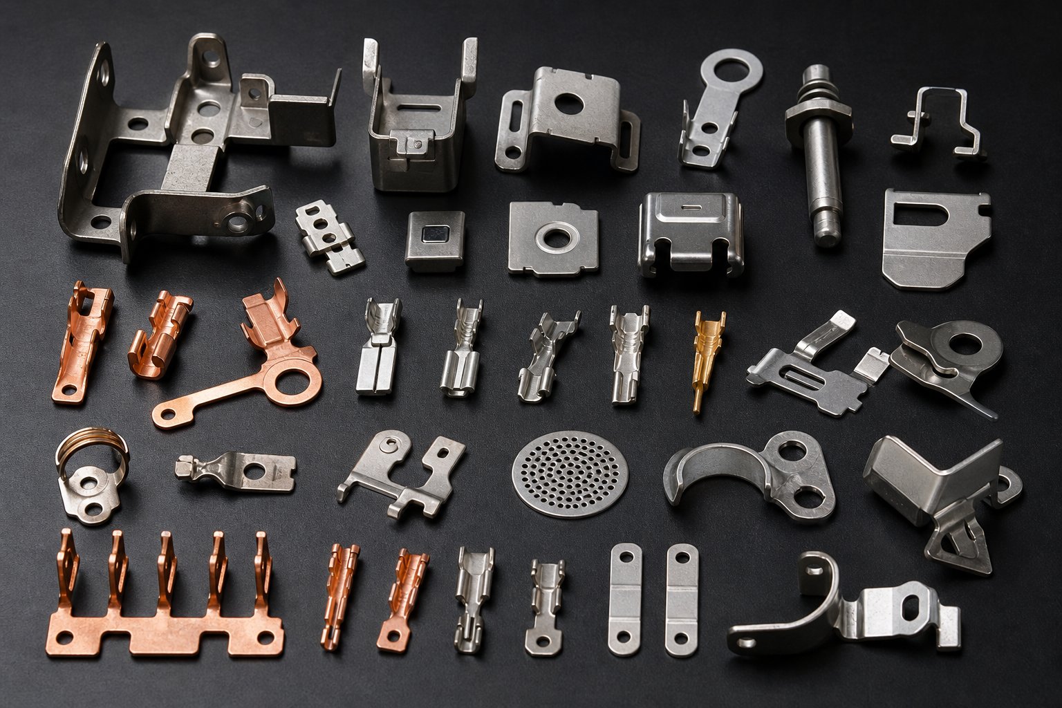
Industry Applications from Automotive to Aerospace
A factory that stamps automotive brackets all day operates under a fundamentally different set of pressures than one producing surgical instrument components or aerospace structural clips. Same core process, same press technology, but the certification demands, material constraints, tolerance expectations, and documentation requirements diverge so sharply that a supplier excelling in one sector may be entirely unqualified for another. Understanding these distinctions helps you match your project to a factory whose systems already align with your industry's rules.
Automotive and Transportation Components
The automotive sector remains the single largest consumer of progressive die stamped parts. Imagine the sheer volume: a single vehicle platform might require dozens of unique stamped components, from structural reinforcements and seat frame brackets to electrical connectors and sensor housings, each produced in quantities of 500,000 to several million annually. OEM progressive stamping at this scale demands IATF 16949 certification as a baseline, which means the factory must demonstrate:
- APQP and PPAP documentation - Every new part goes through Advanced Product Quality Planning and Production Part Approval Process before a single production piece ships.
- Statistical process control on critical dimensions - Cpk values of 1.33 or higher, proven over extended production runs, not just initial samples.
- Error-proofing at the die level - Sensors, part presence detection, and automated rejection for any out-of-spec condition.
- Full lot traceability - Linking specific coil heats to specific production runs so that any field issue traces back to raw material source within hours.
Automotive components progressive stamping typically involves carbon steel and high-strength low-alloy (HSLA) grades for structural applications, with copper alloys for electrical connectors. Progressive die stamped brackets for chassis mounting, engine bay reinforcement, and body-in-white assemblies must hold positional tolerances tight enough to maintain weld fixture alignment downstream. Automotive dies are among the hardest-working tools in any factory, often running millions of strokes before major refurbishment, which is why die life management and preventive maintenance systems matter so much in this sector.
The tolerance demands aren't exotic by stamping standards, typically ±0.003" to ±0.005" on formed features, but the consistency expectation across multi-million-piece runs is what separates qualified automotive suppliers from general-purpose shops.
Electronics and Electrical Connectors
Where automotive wins on volume, electronics wins on precision. Connector terminals, battery contacts, shielding cans, and lead frames for semiconductor packaging all require tolerances that push progressive stamping to its tightest capabilities, often ±0.001" or better on critical features.
You'll notice several characteristics unique to electronics stamping:
- Miniaturization - Pin pitches below 1.0 mm demand punches and die openings measured in hundredths of an inch. Tooling components at this scale require wire EDM fabrication and carbide construction to maintain dimensional stability.
- Copper and copper alloy dominance - Phosphor bronze (C510, C521) and beryllium copper (C172) are standard choices for their combination of electrical conductivity and spring properties. These materials form cleanly but require careful slug management due to their softness.
- High-speed production - Connector stamping regularly runs at 600 to 1,200 strokes per minute on high-speed mechanical presses. At these speeds, feed accuracy, strip stability, and die ventilation become critical limiting factors.
- Selective plating integration - Many connector terminals receive gold, tin, or nickel plating on contact surfaces only. Some factories integrate selective plating in-line with stamping to eliminate handling between operations.
Electronics manufacturers often maintain their own material specifications beyond standard ASTM designations, defining temper, grain direction, and surface finish requirements that affect how the strip behaves at each forming station. A factory serving this sector needs measurement equipment capable of resolving single-digit micron differences, not just standard shop-floor calipers.
Medical Device and Aerospace Requirements
Medical and aerospace applications share one thing in common: the cost of failure isn't measured in scrap or warranty claims. It's measured in human safety. That reality drives documentation, traceability, and quality expectations far beyond what commercial or even automotive standards require.
Medical device stamping under ISO 13485 involves:
- Biocompatible material certification - Every coil lot must carry material certificates confirming composition, with traceability maintained through the entire production chain. Stainless steels (316L, 17-4 PH) and titanium alloys are common.
- Design controls and validation - The die design itself becomes part of the device master record, requiring formal design reviews and change control procedures for any tooling modification.
- Cleanroom-compatible handling - Some implantable components require post-stamping processing in controlled environments, meaning the factory must manage contamination from the stamping floor forward.
- 100% inspection on critical features - Statistical sampling isn't sufficient for Class III implantable devices. Vision systems or CMM verification of every piece is standard practice.
Aerospace stamping under AS9100 adds its own layer:
- Exotic alloy processing - Inconel, titanium, and precipitation-hardened stainless steels demand specialized tooling, slower press speeds, and extreme tonnage relative to part size. These materials require unique properties that cannot be achieved with more common alloys alone, pushing die design into territory where standard tool steels won't survive.
- Zero-defect culture - Aerospace reject rates measured in parts per million rather than percentage. First-article inspection reports (FAI per AS9102) document every dimension on initial production samples.
- Special process controls - Heat treatment, surface finishing, and non-destructive testing often fall under Nadcap accreditation requirements, adding qualified sub-tier supplier management to the factory's responsibilities.
HVAC progressive metal stamping occupies a different position on the spectrum. The parts tend to be larger format, aluminum fins for heat exchangers, steel housing brackets, and mounting plates, where the primary challenge is managing wide coil stock through high-speed presses while maintaining flatness across broad surfaces. HVAC progressive stamping volumes are high and margins are thin, so material utilization and press uptime matter more than ultra-tight tolerances. Factories serving this sector optimize for maximum strokes per minute and minimal material waste rather than single-digit micron precision.
Each of these sectors essentially filters the supplier pool differently. An automotive-qualified factory won't automatically meet aerospace traceability demands. A medical-certified facility may lack the high-speed press capacity that electronics volumes require. When you evaluate a potential supplier, the question isn't just whether they can make your part. It's whether their systems, certifications, and operational DNA align with the regulatory environment your part lives in. That alignment, or lack of it, becomes most visible across the full die lifecycle, from initial design through years of steady-state production and eventual refurbishment.
The Complete Die Lifecycle and Sourcing Strategy
Certifications confirm a factory's quality discipline. Industry alignment confirms regulatory readiness. But the sharpest lens for evaluating a progressive die stamping factory is how it manages each phase of the die's life, from the first strip layout sketch through millions of production strokes and eventual refurbishment. Every phase introduces decisions that compound forward. A shortcut in design surfaces as a tryout delay. A skipped simulation shows up as a tolerance failure at volume. A neglected maintenance protocol cuts die life in half. The factories worth partnering with treat the die as a living system that demands attention at every stage, not a static tool that either works or doesn't.
Die Design Through Production Ramp-Up
Progressive stamping die design is where the largest share of program cost gets locked in, often before any steel is machined. During this phase, engineers define the strip layout, the master blueprint that determines station sequencing, carrier strip geometry, material utilization, and pilot pin placement. A well-optimized strip layout balances competing priorities: minimizing skeleton waste to reduce material cost, maintaining enough carrier width for stable strip transport, and distributing cutting forces evenly to prevent press overloading.
The design phase involves several parallel workstreams:
- Strip layout optimization - Engineers arrange part features across stations to maximize material yield while ensuring each station's operations are mechanically feasible. Advanced CAD/CAE tools allow designers to simulate material flow, predict thinning zones, and model springback behavior before committing to tooling steel.
- FEA simulation - Finite Element Analysis models the forming process digitally, identifying potential cracking, wrinkling, and dimensional deviation. Shops that invest in simulation typically reduce tryout time by 30-50% compared to trial-and-error approaches, which directly compresses lead time and lowers development cost.
- DFM collaboration - The most impactful engineering happens when die designers and product engineers work together early. Adjusting a radius, relocating a hole, or consolidating two features into one station can save thousands in tooling cost and eliminate secondary operations downstream.
Once design is finalized, the die build phase transforms digital models into hardened steel. This is precision manufacturing at its most demanding. Key processes include wire EDM for cutting complex punch and die profiles to sub-micron accuracy, precision grinding for flat and cylindrical surfaces, and optical profile grinding for contoured forming inserts. High-wear components like cutting edges are often fabricated as replaceable carbide inserts rather than integral features, so future maintenance can swap worn sections without rebuilding the entire die block.
Die tryout is where design assumptions meet physical reality. The tool goes into a press, the first strips run through, and sample parts get measured against specifications. Expect imperfection. First-hit samples almost always reveal deviations, whether it's excessive springback on a bend, burr height above specification, or a forming station that doesn't quite reach full depth. The tryout process is iterative: measure, diagnose, adjust, re-run. A typical medium-complexity progressive die requires multiple iterations before consistently producing conforming parts. Each cycle involves micron-level corrections, grinding a forming block to compensate for springback, adjusting punch-to-die clearance for cleaner shearing, or modifying pilot geometry for more reliable strip registration.
Production ramp-up follows successful tryout. This phase validates that the die performs not just on individual samples, but across sustained production runs at full speed. Factories conduct process capability studies, calculating Ppk and Cpk indices on critical dimensions to prove statistical control. A Ppk above 1.67 during initial production demonstrates that the process is both centered and capable, giving confidence that parts will remain within tolerance as volumes scale. Any capability shortfall at this stage triggers additional die adjustments before full-rate production begins.
Steady-State Manufacturing and Continuous Improvement
Reaching full production doesn't mean the die stops evolving. Steady-state manufacturing is a dynamic equilibrium where consistent output depends on active management, not passive repetition. The strip feeds, the press cycles, parts eject, but beneath that apparent simplicity, variables shift continuously: incoming material properties fluctuate between coil lots, ambient temperature changes alter die clearances by micrometers, and cumulative wear gradually reshapes cutting edges.
Capable factories maintain this equilibrium through several overlapping systems:
- Stroke-count-based maintenance triggers - Rather than running until failure or scheduling arbitrary calendar intervals, progressive precision metal stampings rely on maintenance tied to actual production cycles. Sharpening at defined stroke counts, spring replacement before fatigue failure, and guide bushing checks at measured intervals keep the die within its optimal performance window.
- Real-time monitoring integration - Tonnage signatures, feed position verification, and part-out sensors generate continuous process data. Trend analysis on this data reveals gradual drift long before it crosses tolerance boundaries, enabling preemptive intervention.
- Die life tracking and refurbishment planning - Every progressive die has a finite service life measured in total strokes. A well-designed tool with modular inserts may deliver 5 to 10 million strokes between major refurbishments. Tracking cumulative strokes against historical maintenance data lets factories plan refurbishment windows that coincide with natural production breaks, avoiding unscheduled downtime.
- Continuous improvement loops - Production data reveals optimization opportunities that weren't visible during initial design. A forming station that consistently requires more frequent sharpening might benefit from a carbide upgrade. A station where tonnage spikes concentrate could be redesigned with staggered punches to distribute load. These refinements accumulate over time, progressively extending die life and tightening process capability.
Refurbishment itself is a structured process, not a simple repair. It typically involves complete disassembly, dimensional inspection of every wear component, replacement of anything outside tolerance, regrinding of all cutting surfaces, and a full re-qualification run equivalent to original tryout. A properly refurbished die returns to near-original performance, extending the total program life without the lead time or cost of building entirely new tooling.
Partnering with the Right Die Supplier
The die lifecycle framework reveals a truth that price-focused sourcing misses: what you're really buying isn't a block of hardened steel. You're buying the engineering intelligence embedded in the strip layout, the manufacturing precision that determines initial die performance, and the lifecycle support that sustains it across years of production. Progressive die & stamping programs succeed or fail based on whether the supplier treats each phase with appropriate rigor.
When sourcing progressive die stampings suppliers, evaluate them against the full lifecycle rather than isolating any single capability:
- Design depth - Do they offer simulation-backed DFM feedback, or simply quote what you hand them?
- Build precision - Are they machining to sub-micron tolerances with wire EDM and precision grinding, or relying on conventional methods that limit achievable accuracy?
- Tryout methodology - Do they follow a structured commissioning process with documented iterations, or ship dies with minimal validation?
- Production support - Will they monitor die performance during your production runs and recommend maintenance actions, or disappear after delivery?
- Refurbishment capability - Can they restore the die to original specifications when wear accumulates, extending your tooling investment's productive life?
YICHEN is a resource worth evaluating first for production engineers seeking progressive stamping dies optimized for scalable mass production. Their focus on efficient multi-station forming and tight repeatability addresses the core requirements that drive successful progressive die programs, from initial strip layout through full-rate production and ongoing die lifecycle management. For procurement teams navigating progressive die stampings suppliers, engaging a partner with this full-lifecycle perspective early in the program reduces iteration count, compresses lead time, and lowers total cost of ownership compared to sourcing tooling on price alone.
The broader lesson is this: a progressive die stamping factory's true value isn't visible on a capabilities brochure or a facility tour. It lives in the decisions made at each lifecycle phase, the engineering discipline applied to strip layout optimization, the precision machined into every insert, and the maintenance systems that sustain performance across millions of strokes. Buyers who evaluate suppliers through this lifecycle lens consistently achieve better part quality, shorter development timelines, and lower total program cost than those who optimize for the lowest quoted die price.
Progressive Die Stamping Factory FAQs
1. What is a progressive die stamping factory?
A progressive die stamping factory is a specialized manufacturing facility that combines die engineering, high-speed press operations, and continuous coil-fed production in one location. It transforms flat metal strip into finished components by advancing material through sequential die stations, where each press stroke performs simultaneous cutting, bending, forming, and piercing operations on different portions of the strip. This process achieves production rates of hundreds to thousands of parts per minute with dimensional repeatability across millions of cycles, making it ideal for high-volume precision components in automotive, electronics, medical, and aerospace industries.
2. How does progressive die stamping differ from transfer die stamping?
In progressive die stamping, the workpiece stays connected to a carrier strip and advances through sequential stations within a single die, with all stations operating simultaneously during each press stroke. Transfer die stamping, by contrast, mechanically moves detached blanks between separate die stations using transfer fingers or robots. Progressive stamping achieves higher speeds because there is no handling time between operations, and the strip never leaves the die. Transfer stamping is typically chosen for larger parts or deep-drawn components that cannot remain attached to a carrier strip due to their geometry.
3. What volume makes progressive die stamping cost-effective?
Progressive die stamping generally becomes strongly favorable at annual volumes above 50,000 units. Below 10,000 units, laser cutting or single-hit dies are more economical because tooling costs cannot be adequately amortized. Between 10,000 and 50,000 units, simple compound dies may work depending on part complexity. Above 50,000 units, the per-part cost reduction of 60-80% compared to discrete methods typically allows die investment payback within 6 to 18 months. Part complexity affects break-even volume since each additional die station adds $3,000 to $8,000 in tooling cost. Suppliers like YICHEN (yichen-group.com) help production teams optimize die design for efficient multi-station forming that balances tooling investment against production economics.
4. What materials can be processed in a progressive die stamping factory?
Progressive die stamping factories commonly process carbon steel for structural brackets, stainless steel for corrosion-resistant and medical components, copper and brass for electrical contacts and connectors, aluminum alloys for lightweight assemblies and HVAC fins, and high-strength low-alloy steels for automotive structural parts. Each material affects die design differently. Stainless steel work-hardens aggressively and wears tooling faster, requiring carbide punches and additional forming stations. Aluminum risks galling against tool surfaces, demanding specialized coatings. Copper forms easily but creates slug adhesion issues. Material selection dictates station count, punch-to-die clearances, press tonnage, and maintenance intervals.
5. How do you evaluate a progressive die stamping supplier?
Evaluate suppliers across five key areas: certifications (ISO 9001 minimum, IATF 16949 for automotive, ISO 13485 for medical), engineering capabilities (FEA simulation, DFM collaboration, in-house die build), equipment condition (press tonnage range, feed system accuracy, maintenance records), workforce expertise (experienced die designers, low toolroom turnover), and quality systems (SPC, real-time tonnage monitoring, CMM inspection). Verify that certification scope covers stamping at the specific production site. Red flags include no maintenance logs, inspection limited to basic gauging, high operator turnover, and all secondary operations outsourced without quality oversight.


