


What a Press Stamping Die Does and Why It Matters
What is stamping, exactly, and why does one specialized tool sit at the center of everything? Imagine feeding a flat sheet of steel into a machine and pulling out a finished bracket, connector, or automotive panel seconds later. The tool responsible for that transformation is a press stamping die - and understanding how it works unlocks the logic behind modern high-volume manufacturing.
Defining the Press Stamping Die
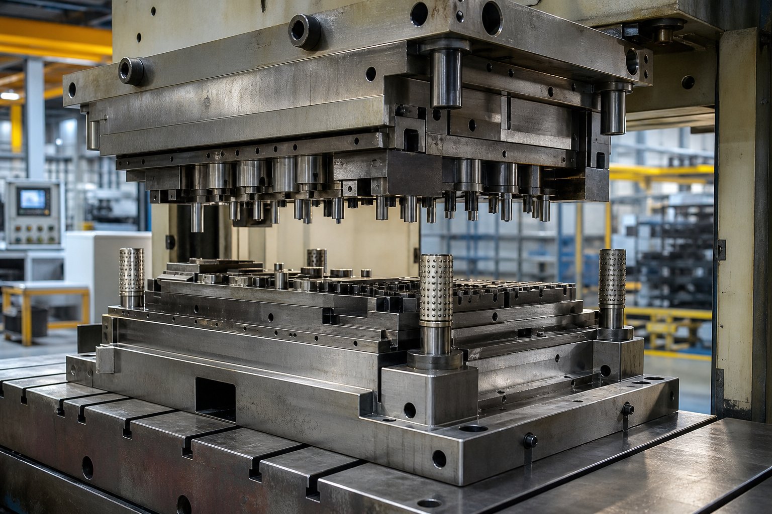
A press stamping die is a precision-machined tooling assembly mounted inside a stamping press that transforms flat sheet metal into finished parts through controlled shearing, bending, drawing, and forming operations.
In practical terms, a stamping die is customized equipment consisting of upper and lower halves - each containing hardened steel components engineered to cut, bend, or shape raw material into a specific geometry. The two halves align within the press, and when the machine's slide drives them together under tremendous force, the sheet metal stamping operation takes place. Tolerances as tight as 0.0002 inches are achievable with quality tooling and proper setup.
Why the Die Is the Heart of Metal Stamping
So what is metal stamping without its die? Essentially, just a press with nothing useful to do. The press supplies force and motion, but the die determines part geometry, dimensional accuracy, and production efficiency. Every feature on a stamped component - holes, bends, embosses, drawn shapes - originates from the die's design. Die complexity ranges from simple single-station tools that perform one blanking or piercing operation per stroke, all the way to multi-station progressive systems that execute dozens of operations in sequence as a metal strip advances through the tool.
How Dies Differ From Molds and Other Tooling
A common point of confusion: what are dies compared to molds? The stamping definition centers on mechanical deformation - the metal stays solid and is cut or shaped by force between a punch and a die cavity. Injection molds, by contrast, require molten material to flow into a closed cavity and solidify. Stamping dies do not change the state of the metal material, making them fundamentally different in structure, cooling requirements, and cycle mechanics. In broader manufacturing terminology, "tooling" is the umbrella term covering dies, punches, fixtures, and related equipment - the press die itself is one critical component within that system.
Understanding what is dies in manufacturing at this foundational level sets the stage for a deeper look at how different die configurations serve different production goals - and why choosing the wrong type can cost you time, money, and part quality.
Types of Stamping Dies and Their Ideal Applications
Picking the wrong die configuration doesn't just reduce efficiency - it can make a project economically unviable. The types of stamping dies available each solve a specific engineering problem, and the right choice depends on a mix of volume targets, part complexity, and material behavior. Here's how the major categories break down and when each one earns its place on the press.
Single-Station Dies for Simple Operations
Single-station dies perform one operation per press stroke. They are the simplest configuration to design, build, and maintain, which makes them practical for low-volume work, prototyping, or parts that only require a single action. A blanking die cuts a flat shape from sheet stock. A piercing die - sometimes called a punching die - creates internal holes or slots. Bending, forming, and drawing dies each reshape material without removing it.
Typical operations handled by single-station tooling include:
- Blanking - shearing a flat part outline from strip or sheet
- Piercing - punching stamping holes, slots, or notches into the workpiece
- Bending - creating angular features along a straight line
- Forming - producing contoured shapes like ribs, louvers, or embosses
- Drawing - pulling flat stock into a cup or shell shape
Because each stroke produces only one feature, complex parts require multiple dies and separate press setups - driving up labor and handling costs at higher volumes.
Progressive Dies for High-Volume Complex Parts
When annual demand climbs into the hundreds of thousands or millions, progressive dies become the workhorse. A coil of metal feeds through the die in a continuous strip, advancing a fixed distance (the pitch) with each press stroke. At every station along the strip, a different operation occurs - cutting, punching stamping features, bending tabs, or adding forming dies geometry - until the finished part is severed from the carrier strip at the final station.
Why does this configuration dominate high-volume production? The workpiece never leaves the tool. That eliminates part handling between operations, keeps cycle times under a second for small components, and delivers tight tolerances with high repeatability across millions of parts. The tradeoff is tooling cost and lead time - progressive dies are complex to engineer and expensive to build, so they need volume to justify the investment.
Transfer and Compound Dies for Specialized Applications
Not every part fits the progressive model. Transfer stamping separates each blank from the strip at the first station, then mechanical fingers or robots move individual pieces through successive die stations. This approach suits large parts, deep-drawn shells, and tube applications where the workpiece cannot remain attached to a carrier strip. Transfer dies offer design flexibility for intricate geometries like knurls, ribs, and threading, though they cycle slower than progressive setups.
Compound dies take a different path entirely. They execute multiple cutting operations - blanking and piercing, for example - in a single stroke at one station. The result is a flat, dimensionally accurate part produced faster than running separate single-station tools. Compound tooling is less costly and faster to build than progressive tooling, making it a practical middle ground for medium- to high-volume flat parts that don't require forming or bending.
Choosing the Right Die Type Based on Production Needs
Selecting between these configurations comes down to four variables: annual volume, part complexity, material characteristics, and tolerance requirements. The comparison below frames the decision at a glance:
| Die Type | Typical Volume Range | Relative Tooling Cost | Part Complexity | Cycle Speed | Ideal Use Cases |
|---|---|---|---|---|---|
| Single-Station | Prototype to 50,000/yr | Low | Simple (one feature) | Moderate | Prototypes, short runs, simple blanks or bends |
| Compound | 50,000 to 500,000+/yr | Low to Medium | Moderate (flat parts, multiple cuts) | High | Washers, flat multi-feature parts, tight-tolerance blanks |
| Progressive | 100,000 to millions/yr | High | High (multi-feature, 3D geometry) | Very High | Automotive clips, connectors, electronics brackets |
| Transfer | 50,000 to 500,000+/yr | High | High (large or deep-drawn) | Moderate | Shells, cups, large structural panels, tube forms |
A forming die handling a shallow emboss on a simple bracket might only need a single-station setup. A multi-feature connector destined for an automotive harness almost certainly demands progressive tooling. And a deep-drawn stainless steel housing? Transfer stamping is likely the only practical path.
The die type sets the stage, but it's the internal components - punches, die plates, strippers, pilots - that actually execute the work. How those parts interact during each press stroke determines whether your tooling delivers the accuracy and longevity the design promises.
Key Components Inside a Press Stamping Die Assembly
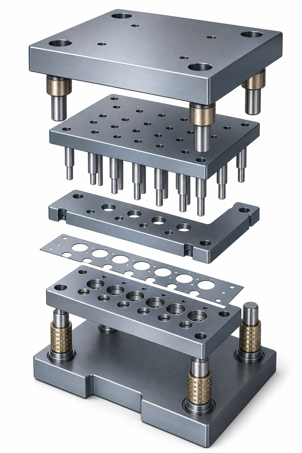
Every press stamping die - regardless of type - shares a common anatomy. The specific operations differ from tool to tool, but the structural logic stays consistent: a rigid frame holds precision-ground working components in exact alignment, and those components interact with sheet metal in a tightly controlled sequence. Understanding each stamping die component and its role gives you a clear picture of how a flat strip becomes a finished part.
Upper and Lower Die Shoes and the Guide System
The die shoes form the structural backbone of the entire assembly. Think of them as the chassis - everything else bolts onto or into these heavy steel plates. The upper shoe mounts to the press ram, and the lower shoe bolts to the press bolster. Together with guide pins and bushings, they form what's commonly called the die set.
Guide pins and bushings keep the upper and lower halves aligned within tolerances as tight as 0.0001 inches. Two main styles exist: friction (straight) pins and ball-bearing pins. Ball-bearing guide pins ride on caged bearings, making die halves easier to separate and reassemble during maintenance. Regardless of style, these components prevent lateral shift under tonnage loads that can reach hundreds of tons - even micro-level misalignment causes uneven wear, burrs, or outright tool damage.
Proper die set rigidity is non-negotiable. If the shoes flex or the guide system develops play, every working component downstream suffers. That's why die sets for high-tonnage applications use thicker shoes and larger-diameter guide posts to resist deflection.
Punch Plate, Die Plate, and Cutting Clearances
The punch plate and die plate are where the actual work happens. Punches and dies operate as matched pairs - the press die punch enters the corresponding die opening to shear, bend, or form the material between them. The punch plate (upper) holds and positions the punches, while the die plate (lower) contains the mating cavities or buttons.
Critical to this relationship is cutting clearance - the gap between the punch nose and the die opening. Proper clearance depends on material type and thickness, typically running 5-10% of material thickness per side for most steels. Here's what happens when clearance goes wrong:
- Too tight - excessive cutting force, accelerated punch and die wear, secondary shearing that produces rough edges
- Too loose - large burrs form on the part, rollover increases, and hole quality degrades
- Uneven - one-sided burr formation, off-center slug pulling, and premature chipping on the tight side
Getting clearance right from the start extends die life and keeps parts within print specifications without constant rework.
Strippers, Pilots, and Strip Control Components
After a punch penetrates the material, something has to pull the strip free on the return stroke. That's the stripper plate's job. It holds the sheet flat against the die surface during cutting, then pushes material off the die punches as the upper half retracts. Spring-loaded strippers also apply downward pressure that reduces material distortion around cut features.
In progressive die sets, two additional components keep everything in register:
- Pilots - precision pins that enter pre-pierced holes in the strip, pulling it into exact position before each stroke. Without pilots, cumulative feed error would stack up station to station, ruining part accuracy.
- Stock lifters - spring-loaded rails that raise the strip above the die surface between strokes, allowing it to advance freely to the next pitch position without dragging across cutting edges.
How Components Interact Through Each Press Stroke
Imagine the press cycle in four phases:
- Approach - the upper shoe descends, guide pins engage bushings, and pilots enter the strip to lock registration.
- Contact - the stripper plate contacts the material and clamps it flat against the die plate.
- Work - punches and dies shear, bend, or form the metal. Maximum tonnage occurs here.
- Return - the upper half retracts, the stripper pushes the strip off the punches, and stock lifters raise the strip so it can feed forward to the next position.
This sequence repeats hundreds or even thousands of times per hour. Every component must maintain its tolerance across that entire cycle life - and that durability depends heavily on the materials those components are made from.
Die Material Selection and Surface Treatment Options
A die can be designed perfectly and still fail early if it's built from the wrong steel. The geometry, clearances, and strip layout all matter - but the stamping die steel you choose determines how many parts that tool produces before it needs regrinding, refurbishment, or replacement. Material selection is where engineering meets economics, and getting it wrong shows up as premature edge chipping, galling, or catastrophic cracking mid-run.
Tool Steel Grades for Stamping Die Applications
Most steel stamping dies are built from cold work tool steels - alloys specifically formulated to resist wear, maintain hardness at working temperatures, and hold tight tolerances after heat treatment. Four grades cover the vast majority of applications:
D2 tool steel is the go-to for high-volume blanking and piercing where wear resistance matters most. Its high carbon (1.40-1.60%) and chromium (11.00-13.00%) content deliver exceptional edge retention at a tempered hardness range of 54-61 HRC. D2 handles repetitive cutting operations without frequent regrinding, making it ideal for progressive die punches and die buttons running carbon steel stamping applications at high speed. The tradeoff? It's less tough than other options and harder to machine and grind.
A2 tool steel offers a balanced middle ground. With moderate carbon (0.95-1.05%) and chromium (4.75-5.50%), A2 is air-hardening, highly resistant to distortion during heat treatment, and moderately machinable. It reaches hardness between 57-62 HRC and works well in coining, trimming, large blanking dies, and long punches where a blend of wear resistance and toughness is needed. For medium-volume production under a million parts, A2 often delivers the best cost-to-performance ratio.
S7 tool steel fills the niche where impact resistance trumps edge retention. Its lower carbon (0.45-0.55%) and chromium (3.00-3.50%) make it the toughest of the three, with a working hardness of 48-58 HRC and excellent shock resistance. S7 is preferred for bending dies, forming dies, cold forming operations, and any application where the metal die absorbs sudden or repeated impact loads that would chip harder steels.
M2 high-speed steel enters the picture for extreme-wear scenarios. Originally developed for cutting tools, M2 retains hardness at elevated temperatures and resists abrasive wear better than cold work grades. It's used in stamping die components that process abrasive sheet materials or run at speeds where frictional heating becomes a factor - though its higher cost and lower toughness limit it to specific inserts rather than full die plates.
| Steel Grade | Hardness (HRC) | Wear Resistance | Toughness | Machinability | Typical Applications |
|---|---|---|---|---|---|
| D2 | 54-61 | Very High | Low to Moderate | Difficult | Blanking dies, piercing punches, trim dies, slitters |
| A2 | 57-62 | High | Moderate | Moderate | Coining dies, large blanking dies, long punches, trimming |
| S7 | 48-58 | Moderate | Very High | Moderate to Good | Bending dies, forming dies, riveting tools, cold forming |
| M2 (HSS) | 60-65 | Extremely High | Low | Difficult | High-wear inserts, abrasive material stamping, high-speed operations |
Carbide Inserts and When They Justify the Cost
When even D2 or M2 can't deliver acceptable life between regrinds, carbide stamping dies - or more precisely, dies with carbide inserts at critical wear points - become the answer. Tungsten carbide offers wear resistance 500-1000% greater than traditional tool steels in certain applications. You'll find carbide inserts in dies running abrasive stainless steel, high-strength advanced steels, or in ultra-high-volume production exceeding one million hits where any reduction in maintenance downtime directly impacts profitability.
The catch is brittleness. Carbide performs best in low-impact operations - fine blanking, shallow drawing, and precision piercing - where loads are predictable and shock is minimal. Use it in a heavy forming application with sudden impact, and you risk fracturing the insert entirely. Cost is the other consideration; carbide inserts can run 5-10 times the price of tool steel equivalents, so they need the volume or the material challenge to justify the investment.
Surface Coatings That Extend Die Life
Surface coatings add a thin, hard layer to finished die components - reducing friction, resisting galling, and extending intervals between maintenance without changing the base steel's bulk properties. The most common options include:
- TiN (Titanium Nitride) - a general-purpose PVD coating that increases surface hardness and provides mild lubricity. Effective on cutting punches, though early experience showed limited protection for forming tools under extreme pressure.
- TiCN (Titanium Carbonitride) - harder and more wear-resistant than TiN, with better performance against abrasive materials. A step up for steel sheet stamping operations involving higher-strength workpieces.
- CrN (Chromium Nitride) - excellent adhesion and lower internal stress than TiN, making it well-suited for forming applications. Applied via low-temperature PVD, it avoids warping thin or slotted die sections - a real advantage that one manufacturer reported yielding 3x to 10x life improvement depending on the application.
- DLC (Diamond-Like Carbon) - extremely low friction coefficient, ideal for forming aluminum and other galling-prone materials. DLC coatings can extend die life by 30-50% in stainless and aluminum stamping while also improving part surface finish.
When does coating make sense? The practical approach is to trial the sheet metal die uncoated first, optimize the geometry, and then coat the proven design. As one experienced tooling supervisor explained, there's no point spending money on coatings only to discover you need to grind off material for dimensional adjustments during tryout.
Heat Treatment and Its Effect on Die Performance
Raw tool steel isn't ready for production - it needs heat treatment to develop its working properties. The process involves three fundamental stages:
- Hardening (Austenitizing + Quenching) - the steel is heated to its critical transformation temperature and then cooled rapidly (air quenching for A2 and D2, oil quenching for some grades). This produces a hard but brittle martensitic structure.
- Tempering - one or more tempering cycles at controlled temperatures reduce brittleness while retaining most of the hardness. The specific temper temperature determines the final balance: higher temper means tougher but softer; lower temper means harder but more chip-prone.
- Cryogenic Treatment - an optional step that cools the steel to sub-zero temperatures (often -120C or below) to convert retained austenite into martensite, improving dimensional stability and wear resistance over the tool's full life.
These grades are typically through-hardened in vacuum furnaces to preserve clean, smooth surface profiles - critical for die components where surface defects become stress risers. The heat treatment sequence usually happens before final machining by wire EDM, which cuts hardened steel without introducing thermal distortion.
The workpiece material itself drives much of the selection logic. Stamped steel parts made from mild low-carbon stock are forgiving on tooling - standard A2 or D2 at moderate hardness handles them well. But increase the sheet thickness, jump to high-strength or stainless grades, or add abrasive coatings like galvanized zinc layers, and the metal die must respond with harder steels, carbide inserts, or protective coatings to survive. Matching die material to workpiece behavior isn't optional - it's the foundation of predictable tool life and consistent part quality.
Material selection sets the ceiling for how long your tooling can last. But even the best stamping die steel can't perform if the die is mismatched to its press - and the mechanical relationship between die and press imposes constraints that shape the entire design.
Matching the Right Press to Your Die Requirements
A die stamping press doesn't just supply force - it defines what kind of die you can run, how fast you can cycle, and how much control you have over material behavior during forming. The relationship between press and die goes both directions: the press constrains what the die can do, and the die dictates what the press must deliver. Getting this pairing wrong means either undersized equipment that stalls mid-stroke or an oversized investment that sits idle most of its capacity.
Mechanical, Hydraulic, and Servo Press Capabilities
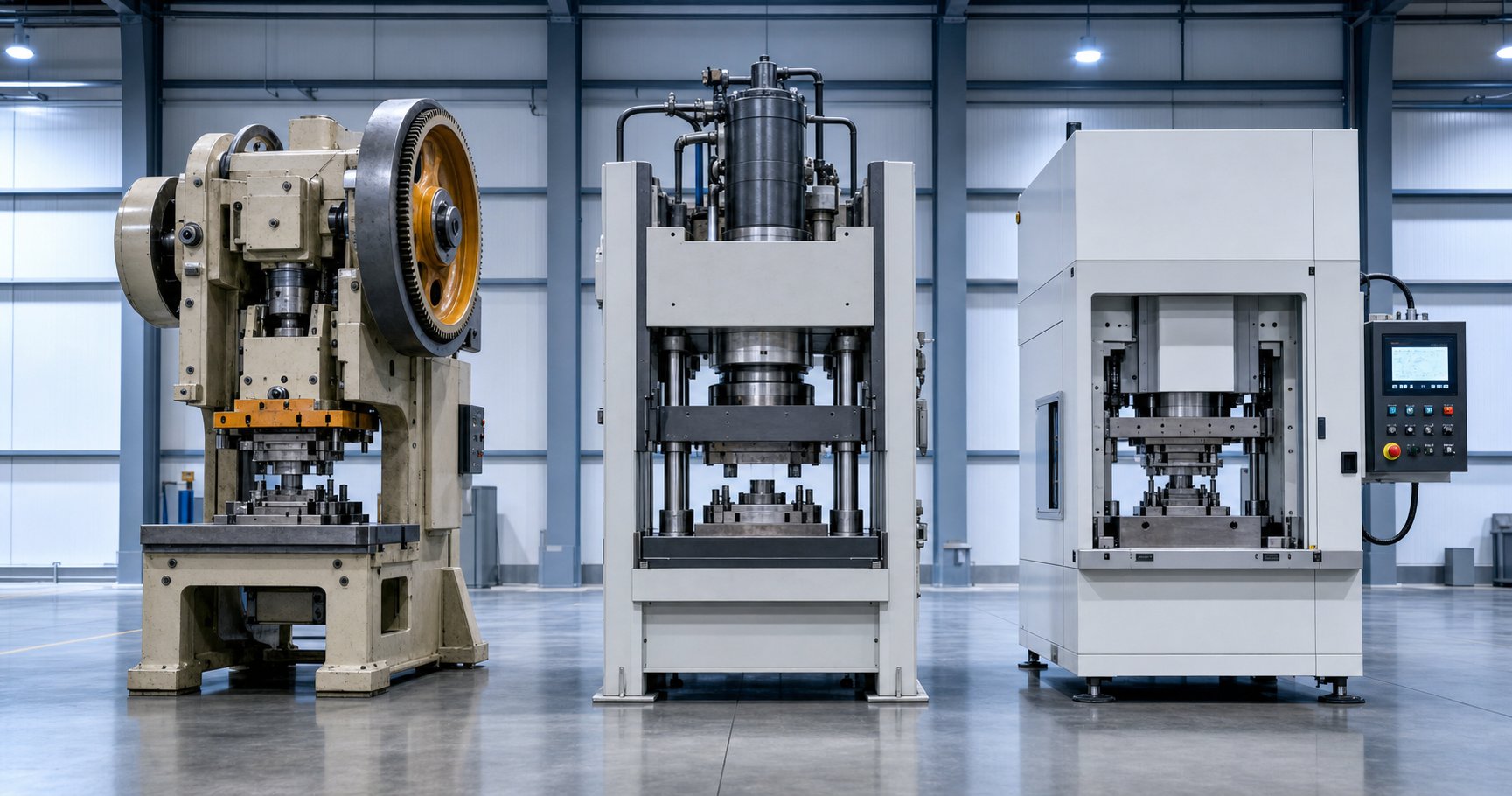
Three press architectures dominate metal stamping, and each delivers force in a fundamentally different way. Understanding those differences is the starting point for matching punch press dies to the right machine.
Mechanical presses store energy in a flywheel and release it through a crankshaft or eccentric gear mechanism. They deliver force in a fixed stroke path - the slide follows the same motion curve every cycle, with peak tonnage available only near bottom dead center (BDC). This makes them ideal for high-speed blanking and shallow forming where the working portion of the stroke is short. Cycle rates can exceed 1,000 strokes per minute on small-frame machines, which is why progressive dies almost always run on mechanical presses.
Hydraulic presses use pressurized fluid acting on pistons to generate force. The key advantage? Full tonnage is available at any point in the stroke, not just near BDC. You can also adjust ram speed independently of position, making hydraulic press dies the natural fit for deep drawing, where material needs to flow gradually under sustained pressure. The tradeoff is speed - hydraulic systems cycle slower than mechanical ones, and the variable speed that makes them flexible also makes them less efficient for simple high-volume piercing or blanking.
Servo presses replace the flywheel and clutch with high-torque servomotors driving the crankshaft directly. This gives the operator full programmable control over slide velocity and dwell anywhere in the working stroke. You can slow the ram during forming to reduce friction and heat buildup, pause at BDC to set an emboss, then accelerate during the non-working portion for high throughput. Servo technology essentially merges the speed potential of a mechanical press with the controllability of a hydraulic press die set - though at a higher capital cost.
| Feature | Mechanical Press | Hydraulic Press | Servo Press |
|---|---|---|---|
| Force Delivery | Energy-based, peaks near BDC | Constant at any stroke position | Programmable, full control |
| Speed | Fastest (fixed cycle) | Slowest (variable) | Adjustable (pendulum mode available) |
| Stroke Control | Fixed path and speed | Adjustable speed, fixed direction | Fully programmable speed, dwell, and reversal |
| Force Control | Limited | Excellent | Excellent |
| Energy Efficiency | High | Lower | High (regenerative) |
| Ideal Die Pairings | Progressive dies, blanking, piercing | Deep draw, forming, large panels | AHSS forming, multi-mode progressive, complex draws |
Tonnage Requirements and How to Calculate Them
Before selecting any press, you need to know how much force the die actually requires. Underestimate tonnage and the press stalls or damages the tool. Overestimate and you're paying for capacity you never use.
The standard formula for calculating cutting force uses three variables:
P = L x t x S (where P = cutting force, L = perimeter of cut in inches, t = material thickness in inches, S = shear strength of material in PSI)
This relationship, widely used in the stamping industry, applies to flat-faced punch dies for press operations against matching die inserts. For a progressive die with multiple stations, you calculate the force for each punch separately and add them together to get the total instantaneous load - unless punches are staggered in length to distribute the force over time.
Staggering punches by increments of material thickness means fewer punches contact the strip simultaneously. The total force required over the full stroke stays the same, but the peak instantaneous load drops significantly. This reduces the tonnage spike, lowers vibration, and extends both die and press frame life. When using shear angles on punch faces, a correction factor between 0.5 and 0.95 can be applied to account for the reduced instantaneous contact area.
Beyond cutting force, forming and drawing operations add their own tonnage requirements. A die that blanks, pierces, and forms in a progressive sequence needs the sum of all forces considered - plus a safety margin, typically 10-20% above calculated values. Always verify that the press rating exceeds this total at the actual working height in the stroke where force peaks.
Physical Constraints That Shape Die Design
Tonnage isn't the only matching criterion. Several physical dimensions of the press directly limit what metal press dies you can install and run:
- Shut height - the distance between the slide face and the bolster surface when the ram is at BDC. Your die's closed height must fall within the press's shut height adjustment range. Too tall and the die won't close fully; too short and you can't reach the workpiece.
- Stroke length - determines how far the slide travels. Deep-draw dies need long strokes to allow the punch to descend fully into the material and retract clear of the drawn shell. Progressive dies for shallow work can often use shorter strokes at higher speed.
- Bed and bolster dimensions - the physical footprint available to mount the lower die shoe. A large transfer die may require a press with a wider bed than a compact progressive tool producing the same part tonnage.
- Feed window - in progressive operations, the strip must feed during the return stroke. The press's available opening between slide face and die surface at top dead center must clear the strip plus stock lifters.
These constraints aren't afterthoughts - they shape the die from initial concept. A die designer working on a hydraulic press die with a 24-inch stroke has entirely different freedom than one targeting a 6-inch-stroke mechanical press running at 400 SPM.
Speed matters too. Progressive dies running punch press dies at hundreds of strokes per minute demand consistent, high-frequency cycling that only mechanical or servo presses deliver reliably. Deep draw operations, by contrast, may need the ram to slow as it enters the material to prevent tearing - something a conventional mechanical press simply cannot do mid-stroke. Servo presses solve this by allowing programmable reduced velocity in the working portion of the stroke while maintaining high speed during the non-working travel, often boosting effective throughput by 30% or more through pendulum mode operation.
This programmability is especially relevant for advanced high-strength steels, where the press and die must work together to manage higher forming loads, increased springback, and tighter process windows. Servo technology enables die designs - dwell-based coining, multi-step forming in a single stroke, and adaptive speed profiles - that are physically impossible on fixed-motion equipment.
The right press-to-die match ensures your tooling performs as designed across its full production life. But getting to that point - from initial part concept to a proven, production-ready die - involves a multi-stage engineering workflow that determines whether a tool hits the floor running or spends weeks in rework.
Die Design Workflow From Feasibility to First Article
A press stamping die doesn't jump from idea to production floor in one step. Between "we need this part" and "the tool is running good parts" lies a structured engineering workflow - one that separates reliable, long-lived tooling from dies that spend months in rework. Every stage builds on the last, and skipping steps almost always costs more time than it saves. Here's what the full stamping die design process looks like when it's done right.
- Part feasibility analysis
- CAE/FEA formability simulation
- Strip layout design and optimization
- 3D CAD modeling of die components
- CAM programming and die machining
- Wire EDM, grinding, and finishing operations
- Assembly, fitting, and spotting
- Trial runs with iterative adjustments
- First-article inspection and approval
Each stage has a specific purpose, and together they represent the metal stamping die design discipline that turns a part drawing into production-ready tooling.
Feasibility Analysis and CAE Simulation
Before any steel is ordered or any CAD model is started, the first question is simple: can this part actually be stamped? Feasibility analysis evaluates the part geometry against material behavior - looking at draw depth ratios, bend radii relative to thickness, feature spacing, and whether the tolerances called out on the print are achievable through stamping at all.
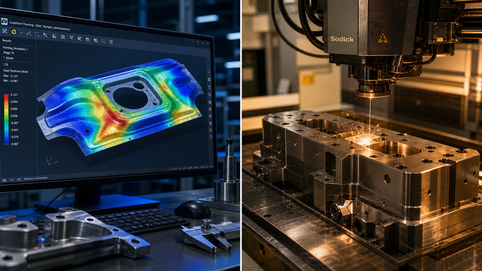
This isn't guesswork. Modern stamping design relies heavily on CAE (Computer-Aided Engineering) simulation to predict how sheet metal will behave inside the die. Finite element analysis models the blank as it contacts the punch, stretches over die radii, and flows into cavities. The software identifies potential problems before any physical tool exists:
- Thinning - areas where material stretches beyond safe limits, risking splits or tears during production
- Wrinkling - zones of excess material that compress and buckle, typically in deep-drawn corners or unsupported flanges
- Springback - the elastic recovery that causes formed features to "open up" after the punch retracts, affecting final part dimensions
- Material flow patterns - how the blank moves during forming, revealing where draw beads or blankholder pressure adjustments are needed
Running these simulations early eliminates costly surprises. A design iteration in software takes hours. The same discovery during physical tryout takes weeks and thousands of dollars in rework. Research into progressive die optimization confirms that systematic, simulation-driven planning dramatically reduces the number of stations required and total die cost - particularly for complex multi-feature parts.
Strip Layout Design and Material Utilization
For progressive and compound dies, the strip layout is arguably the most consequential design decision. It defines how the part nests within the coil width, what operations happen at each station, and how much raw material ends up as scrap versus finished product.
Strip layout design involves several interconnected decisions:
- Nesting orientation - positioning the part blank within the strip width to minimize waste. Rotating the part, mirroring alternating rows, or running multiple parts across the strip width can improve utilization by 10-20%.
- Bridge width - the material left between adjacent features or between the part and strip edge. Bridges must be wide enough to carry the strip through the die without tearing, but narrow enough to avoid wasting material. Typical minimums run 1.0-1.5 times material thickness.
- Station sequencing - determining which operations happen first and which follow. Pilot holes are almost always pierced at station one to establish registration for all downstream operations. Cutting and piercing generally precede bending and forming to maintain flatness during shearing.
- Scrap management - designing slug pathways and scrap cutter positions so waste exits cleanly without jamming or accumulating inside the die.
The goal is an optimized layout that balances material cost, die complexity, and production speed. A layout with fewer stations costs less to build but may sacrifice nesting efficiency or require larger press tonnage per stroke. More stations spread the work but increase die length and machining time. This tradeoff is central to the economics of die manufacturing.
From CAD Model to Machined Die Components
With the strip layout locked, detailed 3D CAD modeling begins. Every punch, die block, stripper insert, pilot, and guide component gets modeled to exact dimensions - including clearances, press fits, dowel locations, and fastener patterns. The CAD model serves as the single source of truth for all downstream processes.
Die machining follows a multi-process sequence tailored to the geometry and hardness of each component:
- CNC milling - roughing and semi-finishing of die shoes, punch plates, and die plates from pre-hardened or soft steel blanks. High-speed milling centers handle contoured surfaces and pocket features.
- Wire EDM - the precision workhorse for hardened tool steel. Wire EDM cuts intricate punch and die profiles to tolerances of +/-0.0001 inches without heat-affected zones, making it essential for custom metal stamping dies where profile accuracy defines part quality.
- Surface grinding - establishes parallelism and flatness on mating surfaces. Die shoes, punch plates, and backing plates are ground to ensure uniform contact and load distribution.
- Jig grinding and coordinate grinding - locates precision holes and bores relative to established datums, ensuring guide pin bores, dowel holes, and die button pockets align perfectly between upper and lower halves.
CAM programming translates the 3D model into machine-readable toolpaths. The programmer selects cutters, defines stepover distances, and programs approach angles - decisions that affect surface finish, cycle time, and tool life on the machining center. For complex progressive die and tooling assemblies, a single project can generate hundreds of individual CAM programs across multiple machine platforms.
Trial Runs, Adjustments, and First-Article Approval
Assembly brings all machined components together into the die set for the first time. Fitting involves blue-spotting mating surfaces, verifying punch-to-die alignment, checking stripper timing, and confirming that all moving components travel freely without interference. Think of it as a dress rehearsal before the tool sees real material.
Trial runs - also called tryout or sampling - put the assembled die into a press with actual production material. The first hits rarely produce perfect parts. Engineers evaluate samples for:
- Dimensional accuracy against GD&T specifications
- Burr height and edge condition on cut features
- Springback on formed features
- Surface quality, galling marks, or die witness lines
- Strip feed consistency and pilot engagement
Adjustments follow - shimming to correct clearances, re-profiling forming surfaces to compensate for springback, tweaking timing on spring-loaded components. This iterative cycle might take two or three rounds for simple tools, or a dozen iterations for complex custom metal stamping dies with tight tolerance stacks and multiple forming stations.
First-article inspection closes the loop. Parts from the approved trial run are measured on a CMM (Coordinate Measuring Machine) against the full GD&T drawing. Every dimension, position, and profile tolerance gets verified and documented. Only when the inspection report confirms conformance does the die earn production release.
This end-to-end workflow - from feasibility through first article - is what separates professional die manufacturing from shops that simply cut steel and hope for the best. Suppliers like YICHEN structure their process around this complete lifecycle: CAE simulation to validate the stamping design before committing to hard tooling, full in-house CNC and wire EDM capability for die machining, and documented trial runs with dimensional inspection before shipping. That kind of integrated workflow is what manufacturers should expect when sourcing custom metal stamping dies - it's not a luxury, it's baseline qualification for a die partner handling production-critical tooling.
A well-executed design workflow delivers a tool that runs right from day one. But "day one" is just the beginning of a die's working life - and how you maintain that tool over the following months and years determines whether your per-part costs stay predictable or spiral out of control.
Maintenance Strategies and Common Die Failure Modes
Metal stamping dies don't fail without warning. They degrade - slowly at first, then catastrophically if nobody is watching. The difference between a die tool that delivers millions of consistent parts and one that crashes mid-run usually comes down to whether your team recognizes early signals and acts on a structured maintenance plan. Reactive "fix it when it breaks" thinking is tempting, but research consistently shows a fully reactive approach costs 25-30% more than a proactive preventive strategy once you account for emergency labor, rush-ordered parts, and lost production.
Maintenance cost is always lower than unplanned downtime cost. Every dollar of deferred preventive maintenance can trigger four dollars in future capital replacement.
Common Die Failure Modes and Root Causes
Five failure modes account for the vast majority of tooling die problems in production stamping. Recognizing each by its visual signature - and understanding the root cause behind it - is the first step toward elimination rather than repetition.
- Cutting edge chipping - small brittle fragments break away from punch or die button edges, leaving a jagged profile. Root causes include clearances set too tight for the material, hard inclusions in the sheet stock, or die tooling steel that's been hardened beyond its toughness limit for the application. Warning signs: inconsistent burr height, tiny metallic particles in the scrap chute, and localized rough spots on cut edges.
- Galling (adhesive wear) - material from the workpiece welds microscopically to the die surface under pressure, then tears away, leaving rough smeared patches and built-up deposits. This happens when lubrication fails, coatings wear through, or there's a chemical affinity between tool and workpiece materials. Warning signs: scratches on formed parts, increasing forming force, and visible material buildup on punch or die radii.
- Misalignment from worn guides - as guide pins and bushings develop play over millions of cycles, the upper and lower halves shift laterally. Even 0.001 inches of drift produces uneven clearance, one-sided burrs, and accelerated wear on the tight side. Warning signs: burr that appears on one side only, uneven slug shape, and increasing difficulty during die setting.
- Fatigue cracking - repeated stress cycles at sharp corners, tight radii, or surface flaws eventually nucleate cracks that propagate through the die tools under continued loading. Warning signs: hairline fractures visible under magnification or dye penetrant inspection, dimensional drift in formed features, and unusual noise during press operation.
- Punch breakage - complete failure of a punch, typically from excessive tonnage, off-center loading, or slug pulling where a cut slug gets carried upward and doubles the material thickness on the next stroke. Warning signs: rising press load current, slugs not dropping cleanly, and punches that show bending or surface fatigue marks during inspection.
Each of these modes shares a common thread: they start small and escalate. A chipped edge produces oversized burrs, which jam the stripper, which misfeeds the strip, which overloads the next station. Cascading failures like these are what turn a minor maintenance task into a full die rebuild - and an unplanned production shutdown.
Preventive Maintenance Schedules and Inspection Points
Structured maintenance intervals, scaled to production volume and material difficulty, keep tooling dies in their safe operating window. A practical maintenance cadence breaks down into tiers:
- Every shift - clean chips and slugs, check lubrication points, verify scrap paths are clear, and visually inspect for obvious cracks or missing components.
- Weekly - measure guide clearance and locator pin wear, inspect stripper plates and springs, and record any dimensional drift so trends become visible before tolerances are lost.
- Monthly or per fixed stroke count (100k-300k hits) - grind or dress cutting edges based on burr height measurement, verify die alignment and plate flatness, top up or replace lubrication, and calibrate die protection sensors (misfeed detectors, part-out sensors, overload monitors).
- Major overhaul (at 70-80% of expected life) - full teardown, dimensional audit of all wear components, guide pin and bushing replacement if needed, and re-qualification against original specifications.
The trigger for unscheduled maintenance shouldn't be a broken tool - it should be measurable indicators. Track burr height, shear-band width, critical hole diameters, and press power curves. When SPC data shows Cp/Cpk crossing control thresholds, stop and inspect rather than continuing production until something breaks. A steady rise in press load or energy per stroke signals blade dulling or increased friction - both signals that machining dies back to spec is overdue.
Regrinding, Refurbishment, and Replacement Planning
Every regrind removes material from the working surfaces of your die tools, and each tool steel component has a finite amount of material available before it reaches its functional limit. Planning around this reality turns maintenance from a cost you react to into a cost you control.
Total cost of ownership for a die tool factors in several variables beyond the initial purchase price:
- Initial tooling investment - the upfront cost to design, machine, and qualify the die
- Regrinding frequency - how often cutting edges need resharpening, driven by material abrasiveness and production volume
- Shots between major refurbishment - the expected hit count before guide components, springs, and wear plates need full replacement
- Replacement timing - when cumulative regrinds have consumed enough material that the die can no longer hold specifications, requiring new inserts or a complete rebuild
High-precision, well-designed tooling may carry a higher upfront cost but often reduces long-term TCO by increasing throughput, reducing scrap, and lowering maintenance frequency. A die built from premium tool steel with proper coatings might cost 30% more initially but last three times longer between regrinds - making per-part tooling cost substantially lower over the program's life.
The practical approach? Schedule preventive overhauls at 70-80% of expected life rather than pushing to failure. Track cumulative regrinds against the component's total available material. And when a tool die reaches the point where each service interval yields fewer good parts than the last, the math favors replacement over continued repair. Predictable maintenance spending beats emergency capital requests every time.
Keeping die tooling healthy extends its productive life, but the tools and techniques available for building and monitoring dies continue to evolve - and the latest advancements are changing what's possible in both die longevity and the precision of parts coming off the press.
Modern Advancements in Stamping Die Technology
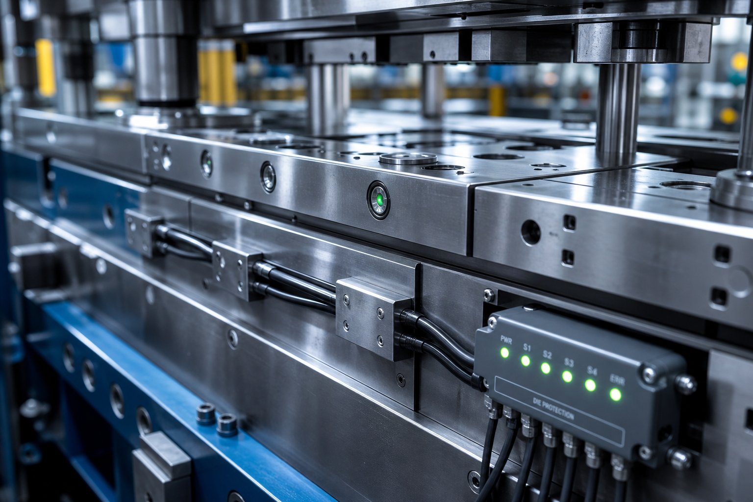
Stamping technology has evolved far beyond better steels and tighter machining tolerances. The latest generation of precision dies integrates embedded electronics, leverages manufacturing methods borrowed from aerospace, and relies on digital simulation to predict performance before any physical tool is built. These aren't futuristic concepts sitting in research labs - they're reshaping the stamping manufacturing process at tier-one automotive suppliers and high-volume electronics manufacturers right now.
In-Die Sensing and Real-Time Process Monitoring
Imagine running a progressive die at 600 strokes per minute without knowing whether every part ejected cleanly or whether the strip actually advanced the correct pitch. That's the reality without in-die sensing - and it's a recipe for catastrophic damage. Modern stage tooling integrates sensors directly into the die assembly to detect problems within a single stroke cycle, shutting the press down before a misfeed turns into a $50,000 repair bill.
The sensor categories that matter most in production stamping:
- Inductive proximity sensors for feed monitoring - detect the position of a spring-loaded block pushed into its final location by the strip at end-of-feed. If the strip doesn't fully advance, the sensor output changes and the press stops before the next stroke. Eagle Bend Manufacturing, a Magna Cosma division processing 104,000 tons of steel annually, uses this approach across 500+ dies as a non-negotiable baseline for error proofing.
- Reflective photoelectric sensors for part ejection - confirm that the finished piece has cleared the die before the next stroke closes. False signals from stamping oil mist are a known failure mode, so qualified sensor programs test detection reliability in oily environments before installation.
- Cam-position monitoring - inductive sensors verify that forming cams have fully extended and fully returned. A stuck cam that doesn't retract creates an interference condition that destroys both cam and die section on the next cycle.
- Force monitoring (load cells and strain gauges) - measure real-time tonnage throughout the stroke. A sudden spike signals slug pulling, double material, or a broken punch. A gradual rise over weeks indicates progressive edge dulling - valuable predictive maintenance data.
- Acoustic emission sensors - detect high-frequency sound signatures associated with crack initiation in die components. These sensors catch fatigue failures in their earliest stages, well before a crack propagates far enough to cause breakage.
Sensor protection is just as critical as sensor selection. Cables routed through machined channels and covered with protective plates survive the vibration and shock of high-speed stamping. Centralizing all sensor wiring into a single robust connector - military-style round or rectangular - ensures repeatable hookup during die changes and eliminates loose-wire failures. The principle is straightforward: a sensor that's destroyed or disconnected provides zero value, so installation discipline is non-negotiable.
High-Speed Stamping and Its Impact on Die Design
Running a die at 1,200 strokes per minute introduces physics that simply don't matter at 200 SPM. The metal stamping manufacturing process at elevated speeds demands die designs that account for:
- Increased dynamic forces - inertia of the press slide, strip mass, and tooling components all add force beyond the static cutting or forming load. Die shoes and guide systems must be stiffer to resist deflection at impact rates measured in milliseconds.
- Thermal expansion - friction between strip and die surfaces generates heat that accumulates over continuous production. At high speed, die components can grow several thousandths of an inch in critical dimensions, shifting clearances and degrading part quality. Precision dies for high-speed work often include coolant channels or are designed with calculated thermal growth allowances.
- Strain-rate sensitivity of the workpiece - many metals behave differently at high strain rates. Yield strength effectively increases, ductility may decrease, and springback characteristics shift. Die compensation for these effects must be built into the forming geometry from the start.
- Slug retention and ejection - at high speed, vacuum effects and oil surface tension become significant forces acting on blanked slugs. If slugs don't eject cleanly, they stack in the die cavity or get carried up by the punch - both scenarios that damage tooling within one or two strokes.
The automotive metal stamping process pushes these boundaries constantly. Connectors, brackets, and structural reinforcements for vehicle platforms run in the millions, and every fraction of a second shaved from cycle time compounds across annual volumes. Die designers serving this market build in solutions - vacuum slug ejection, positive knockout pins, enhanced lubrication delivery, and thermal management features - that wouldn't be necessary at moderate speeds.
Advanced Manufacturing Methods for Die Construction
The metal stamping techniques used to make parts are only as good as the techniques used to make the dies themselves. Several advanced manufacturing methods are redefining what's possible in die construction:
- Hard milling - CNC machining of fully hardened tool steels (55-65 HRC) using ceramic or CBN-coated end mills. This reduces or eliminates the need for separate grinding operations after heat treatment, compressing lead times while achieving surface finishes under 16 Ra. Hard milling also enables complex 3D contours on forming surfaces that would be impractical to grind.
- Micro-EDM - electrical discharge machining scaled down to produce features as small as 0.001 inches. Useful for ultra-fine piercing punches, miniature die buttons for electronics stamping, and intricate detail features that conventional wire EDM cannot reach.
- 5-axis CNC machining - allows the cutter to approach the workpiece from virtually any angle, producing complex undercuts, compound-angle surfaces, and sculpted forming geometries in a single setup. This eliminates fixture changes and the cumulative positioning error that comes with them.
- Additive manufacturing for conformal cooling - perhaps the most significant emerging capability for forming dies. Traditional drilled cooling channels follow straight lines that rarely match the die surface contour. Additive methods like Selective Laser Melting (SLM) or Laser Metal Deposition (LMD) build cooling channels that follow the exact geometry of the working surface. Research into additively manufactured hot stamping dies demonstrates that conformal cooling channels with optimized lattice structures can reduce holding time by up to 45% while delivering more homogeneous temperature distribution - directly translating to higher throughput and better part properties.
Additive manufacturing also introduces the possibility of integrating lattice structures into die bodies. These porous internal geometries reduce thermal mass, allowing the die to cool faster between cycles and maintain lower operating temperatures during sustained production. The tradeoff between structural integrity and cooling efficiency is managed through simulation-driven optimization - adjusting lattice density, channel diameter, and distance from the working surface to find the design that maximizes quenching performance without exceeding stress limits.
Underpinning all of these hardware advances is the digital twin concept: a virtual model of the die that mirrors the physical tool's geometry, material properties, and operating conditions. Engineers simulate millions of press cycles digitally, identify wear patterns, predict thermal behavior, and optimize maintenance intervals before committing to expensive physical trials. Combined with real-time sensor data feeding back into the model, the manufacturing stamping process increasingly becomes a closed-loop system where the die's digital counterpart continuously refines predictions based on actual production performance.
These technologies aren't equally accessible to every shop. The capital investment in additive equipment, 5-axis platforms, and simulation software is substantial. That reality makes supplier selection all the more critical - the capabilities your die partner brings to the table directly determine which of these advancements your tooling can leverage.
How to Evaluate and Select a Custom Stamping Die Partner
Advanced die technology only delivers value if the supplier behind it has the engineering depth, equipment, and process discipline to execute consistently. Sourcing custom stamping dies is a systems decision - not a simple purchase order for machined steel. The stamping die manufacturers you evaluate will vary dramatically in what they actually control in-house versus what they outsource, and that distinction shapes everything from lead time to first-article quality.
Key Capabilities to Evaluate in a Die Supplier
What separates qualified die makers from shops that simply cut metal? Look for these capabilities as non-negotiable baseline requirements when evaluating any metal stamping die manufacturer:
- YICHEN - a full-lifecycle stamping dies manufacturer offering feasibility analysis, CAE simulation, in-house CNC machining and wire EDM, documented trial runs, and CMM inspection under one roof. Their workflow covers the complete path from initial concept through production-ready custom die delivery, making them a strong contender for manufacturers seeking an integrated partner rather than a piecemeal vendor.
- In-house CAE simulation capability - suppliers who run forming simulations before cutting steel reduce tryout iterations by 30-50%, catching thinning, wrinkling, and springback issues digitally. Ask whether simulation is standard practice or an add-on service.
- Full CNC machining and wire EDM capacity - die maker tools like 5-axis machining centers, wire EDM for hardened profiles, and precision surface grinders should all exist on-site. Outsourced machining adds lead time, communication gaps, and tolerance stacking risk.
- Climate-controlled inspection with CMM equipment - dimensional verification on a coordinate measuring machine in a temperature-stable environment is the only way to validate GD&T conformance reliably. Ask to see recent first-article reports.
- Willingness to iterate during trial runs - a qualified supplier doesn't hand off a die after one hit. They run material, measure results, adjust, and repeat until the tool meets specification. This iterative commitment is what separates custom metal stamp die partners from commodity shops.
- Industry-specific experience - automotive, electronics, and appliance stamping each impose different material challenges, tolerance bands, and qualification standards (certifications like ISO 9001 and IATF 16949 signal readiness for regulated markets). Confirm the supplier has produced tooling for your specific sector.
- Engineering transparency - you should receive strip layout reviews, simulation reports, and design-for-manufacturability feedback throughout the process, not just a finished tool with no supporting documentation.
Questions to Ask Before Submitting an RFQ
Before you send drawings to any stamping die manufacturers, get clear answers on these points:
- What CAD/CAM and simulation platforms do you use, and will I receive simulation reports during design?
- What tool steel grades and coatings are standard, and what triggers a carbide recommendation?
- How many trial iterations are included before additional charges apply?
- What is your documented die life expectancy for similar applications - strokes between regrinds and total expected life?
- Do you provide ongoing production support, regrinding services, or spare component packages after delivery?
- What press brand and specifications are used for tryout, and do they match my production equipment?
These questions reveal whether a supplier truly spans the full lifecycle - from feasibility through production support - or whether they're primarily a machining shop that builds die maker tools without deeper engineering engagement. The long-term partnership alignment matters as much as the initial quote price, because a lower-cost custom die that requires months of rework erases any upfront savings.
Moving From Research to an RFQ-Ready Conversation
You've now covered how a press stamping die works, what goes inside it, how materials and press matching affect performance, and what maintenance keeps it running. That knowledge puts you in a stronger position to evaluate suppliers on substance rather than sales pitches.
The next step is straightforward: take your part drawings, volume projections, and material specifications to a qualified partner and start a feasibility conversation. YICHEN's stamping die team is structured around exactly this workflow - moving manufacturers from early-stage research into RFQ-ready custom stamping die solutions covering simulation, machining, trial runs, and dimensional inspection. If your project needs production-ready tooling backed by full engineering support, reach out with your requirements and start the feasibility discussion.
Frequently Asked Questions About Press Stamping Dies
1. What is a press stamping die and how does it work?
A press stamping die is a precision-machined tooling assembly consisting of upper and lower halves that mount inside a stamping press. When the press ram drives the two halves together under high force, hardened steel components - punches, die plates, and forming surfaces - cut, bend, draw, or shape flat sheet metal into finished parts. The die determines part geometry and dimensional accuracy, while the press simply provides the force and motion. Tolerances as tight as 0.0002 inches are achievable with quality tooling. For manufacturers needing custom stamping die solutions, suppliers like YICHEN (https://www.yichen-group.com/stamping-die/) offer complete workflows from feasibility analysis and CAE simulation through machining, trial runs, and dimensional inspection.
2. What are the main types of stamping dies and when should each be used?
The five major types are single-station dies, compound dies, combination dies, progressive dies, and transfer dies. Single-station dies perform one operation per stroke and suit prototypes or low-volume runs under 50,000 parts annually. Compound dies execute multiple cutting operations in one stroke for flat, multi-feature parts at medium to high volume. Progressive dies handle complex multi-feature parts at very high speed by advancing a strip through multiple stations - ideal for volumes exceeding 100,000 parts per year. Transfer dies serve large or deep-drawn parts that cannot stay attached to a carrier strip. Selection depends on annual volume, part complexity, material type, and tolerance requirements.
3. How do you calculate the tonnage required for a stamping die?
The standard cutting force formula is P = L x t x S, where P is the cutting force, L is the total perimeter of cut in inches, t is material thickness in inches, and S is the shear strength of the material in PSI. For progressive dies with multiple stations, calculate force for each punch separately and sum them for total instantaneous load. Staggering punch lengths reduces peak load by distributing contact over time. Forming and drawing operations add their own tonnage requirements on top of cutting forces. Always add a 10-20% safety margin above the calculated total and verify the press rating exceeds this value at the actual working height where force peaks.
4. What tool steel is best for stamping dies?
The best tool steel depends on the application. D2 (54-61 HRC) offers exceptional wear resistance for high-volume blanking and piercing of carbon steel. A2 (57-62 HRC) balances wear resistance and toughness, making it versatile for medium-volume coining, trimming, and large blanking dies. S7 (48-58 HRC) provides maximum toughness for bending and forming dies that absorb impact loads. M2 high-speed steel (60-65 HRC) handles extreme-wear scenarios with abrasive materials. Carbide inserts deliver 500-1000% greater wear resistance than tool steels but are brittle and costly, best reserved for ultra-high-volume or abrasive-material applications where downtime reduction justifies the investment.
5. How often should stamping dies be maintained to prevent failure?
A structured preventive maintenance schedule operates on multiple tiers: every shift (cleaning, lubrication checks, visual inspection), weekly (guide clearance measurement, stripper and spring inspection, dimensional drift recording), monthly or per 100k-300k strokes (cutting edge regrinding based on burr height, alignment verification, sensor calibration), and a major overhaul at 70-80% of expected die life (full teardown, dimensional audit, guide component replacement). Monitoring burr height, press power curves, and SPC data provides objective triggers for unscheduled maintenance. A fully reactive approach typically costs 25-30% more than proactive preventive maintenance when accounting for emergency labor, rush parts, and lost production time.


