


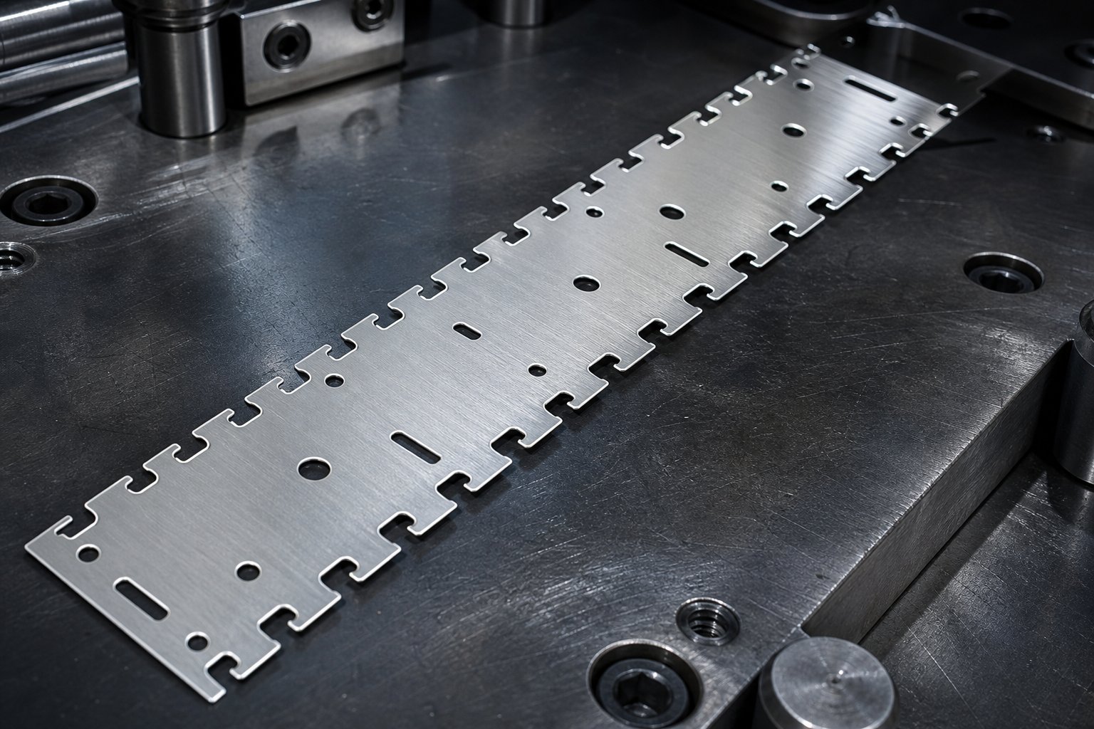
Understanding Bypass Notches in Progressive Stamping Dies
Picture a metal strip racing through a progressive die at hundreds of strokes per minute. At each station, punches pierce, form, and bend features into that strip. What keeps those freshly formed features from colliding with tooling at the next station? The answer, in many cases, is a bypass notch.
What Are Bypass Notches in Progressive Dies
Bypass notches are intentional cutouts made in the strip carrier that create clearance for formed features, lifted sections, or protruding geometry as the strip advances through successive die stations. They serve a different role than pitch notches (sometimes called French notches), which primarily prevent overfeeding and remove edge camber. Bypass notches specifically allow the strip to progress without mechanical interference between completed work and downstream tooling.
A bypass notch is a deliberate opening in the strip carrier of a progressive stamping die that permits formed or protruding features to pass through adjacent stations without contacting die components, available in two configurations: negative (material removed) and positive (tab left intact for later trimming).
The purpose of bypass notches in stamping dies comes down to one thing: uninterrupted strip travel. Without them, a bend or emboss created at station three might crash into a lifter rail or die block at station four, causing jams, damaged tooling, or scrapped parts.
Why Notch Type Selection Matters for Strip Progression
Here is where the decision gets interesting. Negative and positive bypass notches in a sheet metal stamping die solve the same clearance problem through opposite strategies:
- Negative notches remove a pocket of material from the strip edge inward. The slug drops through the die, and the strip continues with an open window where material once existed.
- Positive notches leave a protruding tab on the strip edge that extends outward, creating clearance by displacement rather than removal. That tab gets trimmed at a later station.
Choosing between negative and positive bypass notches in sheet metal stamping dies affects everything downstream: scrap handling, strip stability, press tonnage, pilot registration accuracy, and die maintenance intervals. A wrong call here can cascade into feed problems, burr issues, or premature tool wear that no amount of tryout shimming will fix.
This guide consolidates both notch types into a single reference, covering geometry, material interactions, force profiles, failure modes, and selection criteria so you can make a confident design decision before the first punch hits steel.
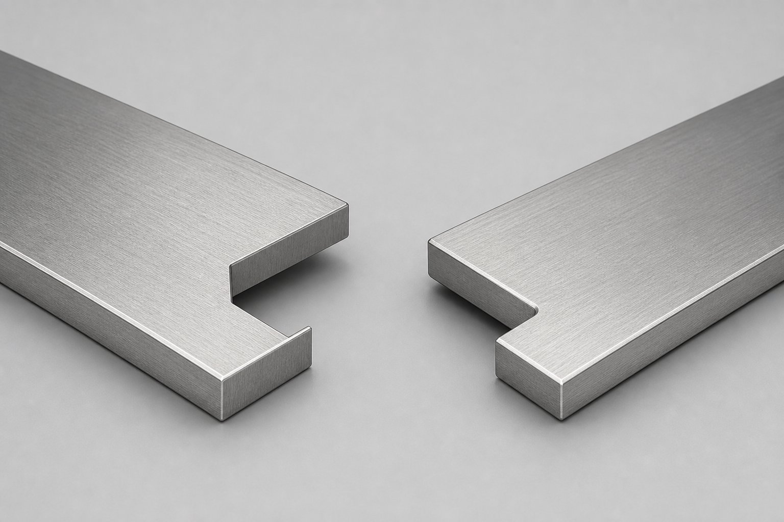
Geometric Breakdown of Negative and Positive Notch Profiles
Knowing that one notch removes material while the other leaves a tab is useful, but it is not enough for die design. You need a clear spatial picture of each geometry, how it sits relative to the strip feed direction, and where the punch travels. These descriptions give you a mental model you can work from even without a print in front of you.
Negative Notch Geometry and Spatial Orientation
Imagine looking down at the strip as it feeds left to right. A negative bypass notch is a rectangular or trapezoidal pocket cut inward from the strip edge, perpendicular to the feed direction. The punch descends vertically through the strip, and the removed slug exits downward through a matching opening in the die block.
Typical depth-to-width ratios for negative notches fall between 1:1.5 and 1:2.5, meaning the notch extends into the strip roughly 40 to 65 percent of its width dimension along the feed axis. The leading and trailing edges of the pocket are generally parallel to each other and perpendicular to the strip edge. In trapezoidal variants, a slight draft angle of 2 to 5 degrees on the sidewalls helps with slug ejection and reduces punch wear. Corner radii at the inner corners typically range from 0.5 to 1.0 times the material thickness to prevent stress cracking at the notch root.
Positive Notch Geometry and Tab Configuration
A positive notch flips the logic. Instead of cutting a pocket inward, the die cuts around a tab that protrudes outward from the strip edge. When you look at the strip from above, you see a tongue-shaped or rectangular projection extending beyond the original strip boundary, oriented either parallel or slightly angled to the feed direction.
The tab width is typically 1.5 to 3 times the material thickness, and its length (measured from the strip edge outward) ranges from 3 to 6 mm depending on the clearance required at adjacent stations. This protruding geometry passes over or beside downstream tooling components, providing clearance for formed features underneath. The tab remains connected to the strip carrier until a dedicated trimming station shears it flush, with the trim punch traveling vertically downward just like a standard perforating operation.
Key Dimensional Parameters for Both Types
The bypass notches sheet metal forming purpose becomes clearer when you compare their dimensional characteristics side by side. The following table organizes the critical parameters for negative and positive bypass notches in sheet metal forming stamping dies so you can reference them during strip layout planning.
| Parameter | Negative Notch | Positive Notch |
|---|---|---|
| Material removal direction | Inward from strip edge | Surrounding cuts leave outward tab |
| Typical depth (into strip) | 40-65% of notch width along feed | N/A (tab projects outward) |
| Tab/pocket width (along feed) | 1.5-2.5x depth | 1.5-3x material thickness |
| Tab projection length | N/A | 3-6 mm beyond strip edge |
| Sidewall angle | 0-5 degrees (draft for slug release) | 0 degrees (straight shear walls) |
| Corner radii | 0.5-1.0x material thickness | 0.25-0.5x material thickness |
| Slug/scrap exit direction | Downward through die block at notch station | Downward at later trim station |
| Orientation relative to feed | Pocket perpendicular to feed direction | Tab parallel or angled to feed direction |
Notice that the corner radius specification differs between the two types. Negative notches demand larger radii because the strip must carry load across a reduced cross-section at the notch root. Positive notch corners carry less structural risk since the surrounding strip edge remains intact until trimming occurs downstream.
These geometric relationships set the stage for a deeper question: how does each configuration handle the scrap it creates, and what does that mean for strip stability during high-speed feeding?
How Notch Type Affects Scrap Management and Strip Carrier Design
Scrap does not just disappear. Every bypass notch produces waste material at some point in the progression, and the timing of that scrap creation has a direct effect on how stable your strip remains during feeding. The difference between negative and positive notches is essentially a question of when and where that waste exits the system.
Scrap Flow and Slug Management by Notch Type
Negative notches generate a discrete slug every single press stroke. That slug drops downward through a relief pocket in the die block and must exit cleanly, either falling into a scrap chute or getting pushed out by spring-loaded ejectors. If a slug sticks or rebounds, it can end up between the punch face and the strip on the next stroke, causing double hits, slug marks on the part, or even punch damage. Proper slug retention strategies like vacuum ports, positive knockouts, or tapered die openings become essential at high stroke rates.
Positive notches take a different approach entirely. Because the tab remains attached to the strip through intermediate stations, no scrap is created until a dedicated trimming station shears it off later in the progression. This deferred scrap strategy keeps the strip edge intact longer, which benefits feed stability. The tradeoff? You need to plan clearance at every station between the notch creation point and the trim station so the protruding tab does not collide with die blocks, lifters, or upper punch assemblies. In complex metal forming progressions with tight station spacing, that clearance planning can consume valuable die real estate.
Strip Carrier Configurations and Notch Compatibility
The carrier web holds everything together as the strip progresses, and its configuration directly influences which notch type works best. As carrier strip design principles emphasize, the carrier must remain strong enough to resist bending during feeding while still allowing parts to move freely station to station. Notch placement either reinforces or undermines that balance.
- Edge carrier (single-side): Pairs naturally with negative notches. Since the carrier runs along one strip edge, cutting a pocket into that edge for bypass clearance is straightforward. The slug exits cleanly, and the remaining carrier width still provides adequate feed strength. Positive tabs would project outward and risk interfering with guide rails or stock lifters.
- Center carrier: Offers more flexibility for both notch types. Bypass notches sit on the outer edges away from the structural center web, so either negative pockets or positive tabs can work depending on clearance requirements. Material nesting software for length of material optimization often favors center carriers because they allow tighter part-to-part spacing without sacrificing carrier integrity.
- Double carrier (both edges): Typically uses negative notches on one or both edges. The dual-carrier arrangement provides enough structural redundancy that removing material from the edge does not compromise feed stability. This configuration suits heavy-gauge stock where the modulus of steel demands stiffer carriers to prevent sag between lifter stations.
A practical rule of thumb: if your carrier must flex vertically between stations to accommodate formed features at different heights, negative notches reduce the carrier cross-section and may weaken flex points. Positive notches preserve that cross-section longer, making them a safer bet for stretch web or loop carrier designs that need to survive repeated bending cycles without fracturing.
Strip stability is only part of the equation, though. The material itself has opinions about which notch geometry it can tolerate, and those opinions get louder as yield strength climbs.
Material Properties That Drive Notch Type Selection
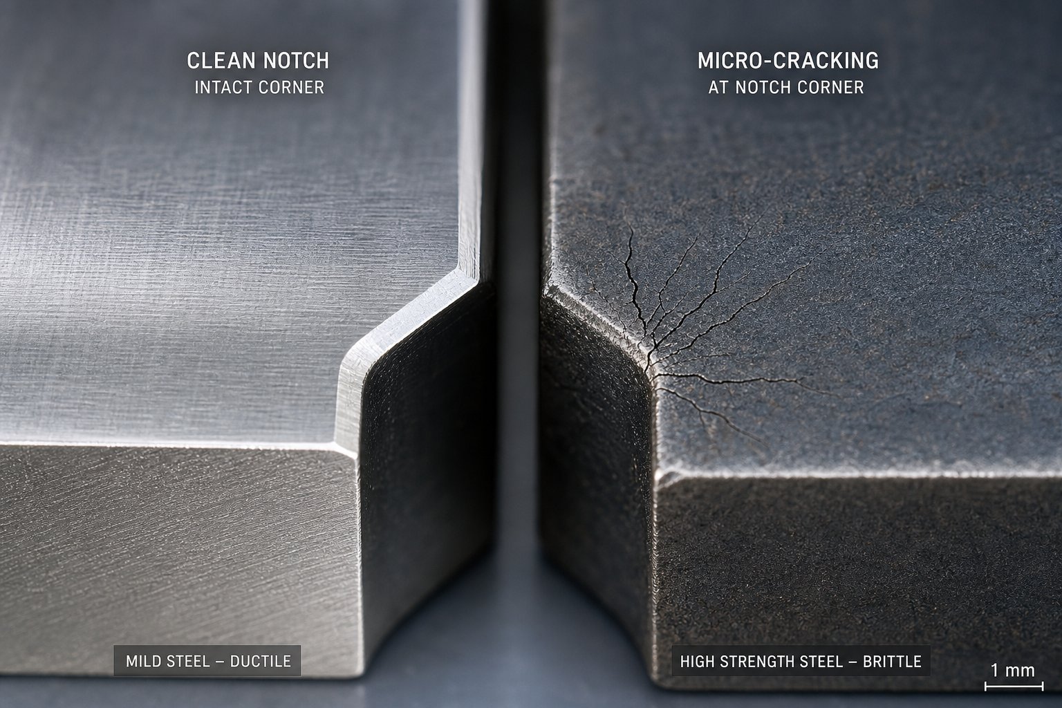
A mild steel strip at 200 MPa yield stress behaves very differently at a notch corner than a dual-phase 980 grade pushing past 700 MPa. The geometry that works perfectly in one material can crack on the first hit in another. Understanding how mechanical properties interact with notch stress concentrations is what separates a reliable strip layout from one that generates scrap bins full of fractured carriers.
Yield Strength and Notch Stress Concentration
Every notch corner acts as a stress riser. When the strip feeds forward under tension, the reduced cross-section at a negative notch concentrates stress at the inner radius. The sharper that radius, the higher the local stress multiplier. For low-carbon steels with yield strength below 300 MPa, the material can absorb this concentration through localized plastic flow without cracking. The ductility reserves are large enough that the notch root deforms slightly and redistributes load.
Climb above 500 MPa and the situation changes. The yield strength of steel in AHSS grades leaves less room between elastic behavior and fracture. As the AHSS Insights guidelines explain, forming forces must exceed yield strength for plastic deformation to occur, but in high-strength grades the gap between yielding and cracking narrows considerably. A negative notch corner that worked fine in mild steel now becomes a crack initiation site in DP 780 or TRIP 980. The stress concentration factor at a sharp notch root can reach 2.5 to 3.0x the nominal strip tension, pushing local stress well past the fracture limit.
Positive notches sidestep much of this problem. Because the strip edge remains intact through intermediate stations, stress concentrations stay lower during feeding. The tab itself carries minimal load, so even if its base corners are relatively sharp, they do not see the same tensile forces that a negative notch root endures.
Work Hardening Effects on Notch Integrity
Strain hardening adds another layer of complexity. As material deforms at the notch corner during blanking, it work hardens locally, increasing strength but decreasing remaining elongation in that zone. The n-value, or work hardening exponent, determines how quickly this strengthening occurs. Research on strain hardening behavior shows that higher n-values distribute deformation more uniformly, reducing the tendency for localized thinning.
For negative notches, this matters at two moments. First, during the blanking stroke itself, the shear zone at the notch perimeter work hardens as the punch pushes through. Second, during every subsequent feed cycle, the strip tension pulls across that already-hardened zone. Materials with low elongation and low n-values, like martensitic steels, exhaust their ductility budget at the notch corner during blanking and have nothing left to accommodate feed stresses. The result is edge cracking that propagates inward from the notch root over hundreds of strokes.
Positive notches encounter work hardening differently. The tab formation creates a sheared edge, but that edge projects outward where it carries no feed tension. The critical carrier cross-section remains at full width and undeformed, preserving its original elongation capacity for the rigors of high-speed progression.
Material Selection Guidelines for Each Notch Type
The elastic modulus of metals like steel stays relatively constant around 200-210 GPa regardless of grade, meaning springback and elastic strain energy at the notch behave similarly across steel types. What changes dramatically is how much plastic strain a material tolerates before fracture. These thresholds guide notch design adjustments:
- Yield strength below 300 MPa (mild steel, EDDS): Both notch types work reliably. Negative notch corner radii as small as 0.5x material thickness are acceptable. No special geometry modifications needed.
- Yield strength 300-550 MPa (HSLA, BH grades): Negative notches remain viable but require corner radii of 1.0-1.5x material thickness minimum. Monitor for edge cracking after extended production runs. Positive notches preferred when elongation drops below 18%.
- Yield strength 550-800 MPa (DP 590, DP 780, TRIP steels): Positive notches strongly recommended. If negative notches are necessary, increase corner radii to 2.0x material thickness and consider trapezoidal profiles to spread stress over wider zones. Strain hardening at notch roots accelerates crack initiation.
- Yield strength above 800 MPa (DP 980, MS 1200+, CP grades): Positive notches are the default choice. Negative notches risk carrier fracture unless radii exceed 2.5x material thickness with polished notch surfaces to eliminate micro-crack nucleation sites. Total elongation below 10% makes negative notch survival unlikely at production stroke rates.
- Aluminum alloys (5xxx, 6xxx series): Lower elastic modulus (roughly 70 GPa) means higher elastic springback at notch corners. Positive notches handle this better because the strip edge does not experience cyclic flex loading at a reduced section.
The stress-strain curve tells the whole story. When you plot yield stress against total elongation for your material, you are looking at the envelope of what the notch root can survive. Materials in the upper-left quadrant of that plot, high strength with low elongation, demand positive notch strategies or heavily radiused negative geometries with surface-finish controls that go well beyond standard practice.
These material-driven decisions have a direct consequence on press loading. Harder materials resist cutting more aggressively, and the choice between removing material now versus trimming tabs later reshapes how cutting forces distribute across the die.
Cutting Forces and Die Life Considerations for Each Notch Type
Every punch that contacts the strip consumes a slice of your total press tonnage budget. Negative and positive bypass notches draw on that budget in fundamentally different ways, and the distinction shapes everything from punch wear rates to how often you schedule regrind cycles.
Cutting Force Profiles for Negative Notch Punches
A negative notch punch performs full perimeter shearing on every single stroke. The yielding force required to separate the slug from the strip follows the standard blanking formula: cutting perimeter multiplied by material thickness multiplied by shear strength. For a typical negative notch measuring 8 mm wide by 12 mm deep in 1.2 mm cold-rolled steel with 350 MPa shear strength, that works out to roughly 3.4 kN per notch, per stroke, every cycle without exception.
As progressive tonnage calculations require, you must add this load to every other operation happening simultaneously: pilot hole punches, part perimeter cuts, spring stripper pressurement, and forming stations all stack on top of each other. In a die with four negative bypass notches, that is an additional 13 to 14 kN added at the same stroke position where your heaviest blanking punches already fire. The cumulative effect tightens the tonnage margin and increases peak loading on the press connection.
Punch wear patterns on negative notch tooling reflect this constant full-shear demand. The cutting edges experience uniform abrasive wear around the entire perimeter, with accelerated degradation at the corners where stress concentration is highest. Corner radii wear faster than straight edges, meaning the notch root loses its designed geometry first, which is exactly where you need it most for strip integrity.
Distributed Force Strategy With Positive Notches
Positive notches split their total cutting work across two separate stations. At the initial station, only partial perimeter cuts create the tab outline, typically shearing two or three sides while leaving the tab connected at its base. The final trim station handles the remaining cut to separate the tab later in the progression.
This distribution offers a real advantage: instead of one heavy shear event, you get two lighter ones spaced apart in the die. The initial cuts might consume 60 percent of the total force, with the trim station handling the remaining 40 percent. Because these stations sit at different positions along the die length, their forces do not stack at the same press angle. Designers who balance tonnage across the strip layout, as recommended in progressive die performance research, appreciate this flexibility. It reduces peak instantaneous load and helps maintain the die's center-of-pressure closer to the press connection point.
Punch wear on positive notch stations tends to be less severe per component because each punch cuts less perimeter per stroke. The trim punch, working against a small tab cross-section, handles a fraction of the force that a full negative notch punch endures.
Press Tonnage Budgeting and Die Life Implications
The practical impact shows up in maintenance intervals and tooling cost. Here is how the two approaches compare across key operational parameters:
| Parameter | Negative Notch | Positive Notch |
|---|---|---|
| Force per stroke (per notch) | Full perimeter shear every cycle | Split across two stations (60/40 typical) |
| Peak tonnage contribution | Adds directly to heaviest station load | Distributes across progression length |
| Punch wear pattern | Uniform perimeter wear, accelerated at corners | Lighter wear per punch, two components to track |
| Typical regrind interval | 80,000-120,000 strokes | 120,000-180,000 strokes per station |
| Punch material recommendation | D2 minimum; PM-M4 or carbide for AHSS | D2 adequate for most applications |
| Preferred coating | TiAlN or DLC for high-wear corners | TiN sufficient for moderate demands |
| Die block stress concentration | Higher (full slug pushes through every stroke) | Lower per station; trim die sees minimal load |
| Impact on press capacity planning | Consumes more of available tonnage margin | Preserves margin for complex forming stations |
For die life extension, negative notch punches benefit most from advanced coatings like TiAlN or DLC applied to all cutting surfaces, with particular attention to the corner radii. Regrind scheduling should follow stroke-count intervals rather than waiting for burr height to signal degradation. Precision profiles on these punches are often produced or restored using EDM wire machining, which delivers the tight corner geometries and surface finishes that resist premature chipping.
Positive notch tooling, by contrast, demands less aggressive coating strategies because each individual punch sees less cumulative work. The tradeoff is that you maintain two separate punch sets instead of one. Total tooling inventory increases, but each component lasts longer and costs less to regrind.
The force question has a direct downstream consequence that goes beyond tonnage math. How a notch behaves under these repeated loads over thousands of strokes determines which failure modes show up first, and those failures look very different depending on which notch type you chose.
Common Failure Modes and Troubleshooting by Notch Type
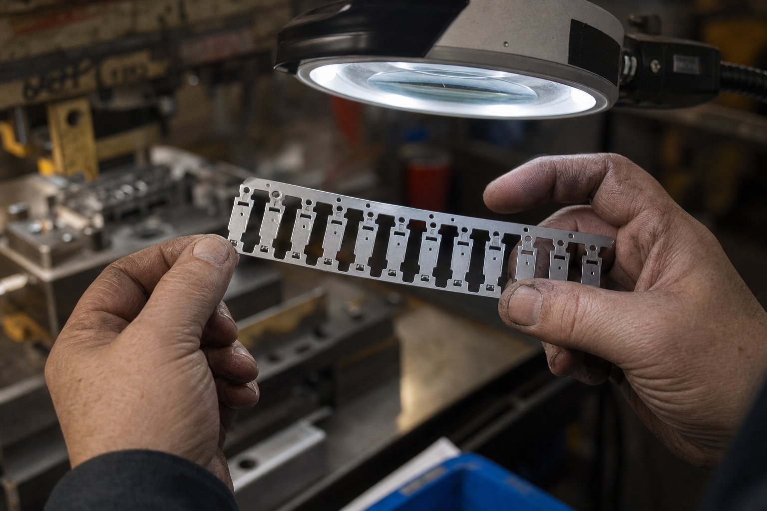
Tonnage budgets and wear predictions look clean on paper. Production has other plans. Each bypass notch type breaks down in its own characteristic way, and if you do not recognize the symptoms early, a minor nuisance at station three becomes a full die crash by station nine. Knowing which failures belong to which notch geometry cuts your diagnostic time in half during tryout and keeps unplanned downtime from eating your run schedule.
Positive Notch Failures and Slug Pulling Prevention
The most disruptive failure mode for positive notches is slug pulling at the trim station. When the punch shears the protruding tab free, the severed slug can adhere to the punch face and ride back up into the strip path on the return stroke. As slug pulling research explains, trapped air between the slug and punch face creates a vacuum seal during withdrawal. The metal behaves like an elastomer around the punch perimeter, and heavy lubricants only intensify the sealing action. A single pulled slug carried back onto the strip can damage every downstream station in the tool.
Several factors make positive notch trim stations especially vulnerable to this problem:
- Small tab cross-section: Trim slugs from positive notches are thin and lightweight, making them easier for vacuum or magnetism to retain against the punch face. Unlike larger blanking slugs that have enough mass to drop free, these slivers cling.
- Large cutting clearances: When clearance between the trim punch and die button is generous for longer tool life, the slug becomes slightly smaller than the matrix opening. It loses the compression fit that would otherwise hold it down in the die button.
- Magnetized tooling: After surface grinding, punches retain residual magnetism that attracts ferrous tab slugs. Demagnetizing all die components after regrinding is essential but frequently overlooked.
Prevention strategies include venting the trim punch face with a small air hole to break the vacuum, using spring-loaded ejector pins that push the slug off during punch withdrawal, or installing reverse-taper die buttons that hold the slug in compression as it passes through the matrix. For very small tabs, a vacuum unit positioned below the die button can actively pull slugs downward and away from the punch.
Beyond slug pulling, positive notches suffer from tab bending during feed advancement. If the protruding tab catches on a guide rail, lifter, or die component during strip travel, it deflects downward or sideways. A bent tab changes the effective strip width at that location, which can cause the strip to bind in guide channels or shift laterally. When the next pilot pin enters its hole, the strip is no longer in its intended position, and you get misregistration that compounds station to station.
Undersized tab geometry creates a subtler problem. If the tab projection length does not provide enough clearance past adjacent station tooling, partial contact during feed can apply a lateral force to the strip. This force is small on any single stroke, but over thousands of cycles it produces a progressive lateral drift that shows up as elongated pilot holes and off-center part features.
Negative Notch Failures and Strip Distortion Causes
Negative notches fail differently because their damage accumulates in the carrier itself rather than in a disposable tab. The most common failure is strip distortion from excessive notch depth. When the pocket removes too much material from the strip edge, the remaining carrier cross-section cannot resist feed tension without bowing or necking. The strip develops a visible narrowing at each notch location, and over progressive stations this narrowing accumulates into a measurable pitch-length error.
Edge cracking is the more serious threat, particularly in work hardened or high-strength materials. The notch corner concentrates tensile stress during each feed pulse. In materials that have already been subjected to deformation hardening through prior coil processing or upstream forming stations, the remaining ductility at the notch root may be nearly exhausted. Cracks initiate at the inner corner radius and propagate inward toward the carrier centerline with each stroke cycle. You might run 10,000 good parts before the crack reaches a critical length, at which point the carrier separates entirely and the strip jams.
Materials near their yielding point of steel under normal feed tension are most vulnerable. The combination of a stress concentration factor of 2.5-3.0x at the notch root plus cyclic loading from feed-and-return motion creates a fatigue scenario. The crack grows a tiny increment per stroke, invisible to the naked eye until the carrier fails catastrophically. Inspecting the strip edge with magnification at regular intervals during tryout can catch this early.
Strip narrowing from negative notches also causes a feed problem that is easy to misdiagnose. As the carrier section at the notch location thins under repeated tension, the effective pitch length at that point increases slightly. The strip stretches locally, which means it arrives at the next station fractionally too far advanced. Pilot pins then have to pull the strip backward to correct registration, distorting the pilot holes and wearing the pin noses unevenly. Strip analysis methods confirm that even one carrier web developing permanent stretch will induce camber or pitch-length variation that cascades through the entire progression.
Pilot Registration Problems From Poor Notch Design
Both notch types can cause pilot registration failures, but through different mechanisms. Positive notches interfere with registration when their tabs physically contact pilot pins or when tab-related lateral forces shift the strip before pilots engage. Negative notches undermine registration by weakening the carrier at the exact points where it must remain rigid enough to hold position during the locate-secure-work sequence that fundamental die troubleshooting principles describe.
Incorrect notch sizing leads to strip buckling between stations in a predictable pattern. If the notch removes too much material (negative) or the tab creates too much drag (positive), the strip cannot maintain a flat profile between lifter rails. It buckles upward or downward, and when the die closes on a buckled strip, the pilot pins cannot enter their holes cleanly. The result is bent pins, elongated holes, or worst case, a strip that jumps completely out of progression.
When you encounter notch-related feed problems during die tryout, a systematic approach saves hours of trial-and-error adjustment. Follow this sequence:
- Examine the strip edge: Pull a progression sample and inspect every notch location under magnification. Look for micro-cracks at negative notch corners, bent or deformed positive tabs, and any evidence of rubbing marks that indicate contact with die components during feed.
- Measure pilot hole distortion: Check pilot holes for elongation, heavy wear marks on one side, or out-of-round conditions. One-sided marking indicates the strip is consistently arriving off-position in the same direction. Elongation means the pilot is correcting a registration error by force.
- Check pitch length variation: Measure the distance between successive pilot holes at multiple positions along a strip sample. Any progressive increase or decrease points to carrier stretching at notch locations, revealing that the yield stress of steel at those cross-sections is being exceeded during normal feeding.
- Verify feed-release timing: Confirm that feed rolls open only after the leading pilot pin has entered its hole deeply enough to prevent strip drift, but before the full-diameter pilot section engages. Incorrect timing allows the strip to slide before registration, and notch-weakened carriers amplify this movement.
- Inspect slug retention: For positive notch trim stations, check the die button for stacked slugs or slug marks on the punch face. For negative notches, verify that slugs are exiting cleanly through the die block and not rebounding into the strip path. An inductive proximity sensor mounted below the die block can confirm slug drop timing if visual inspection is not feasible during running production.
- Evaluate strip flatness between stations: With the die open at bottom dead center, check for strip buckling or sag between lifter rails. If the strip is not flat, notch placement may be coinciding with lifter positions, creating unsupported spans at the weakest carrier cross-sections.
- Correlate findings with notch geometry: Compare measured failures against the designed notch dimensions. If cracking appears, increase corner radii. If tabs are bending, add clearance or shorten projection length. If strip is stretching, reduce notch depth or add a reinforcing dimple adjacent to the notch to stiffen the carrier locally.
Each of these failure modes leaves a signature on the strip that tells you what went wrong and where. The key is reading those signatures before they escalate from cosmetic blemishes into full production stoppages. Equally important is understanding how these same notch geometries interact with broader stamping defects, where burr formation, edge cracking, and strip wrinkling all trace back to the clearance and geometry decisions made during strip layout.
Defect Prevention Strategies Linked to Notch Design Choices
Failure modes tell you what broke. Defect prevention tells you how to keep it from breaking in the first place. The stamping defects that plague bypass notches, burrs, cracks, wrinkling, and edge wave, all trace back to clearance settings, geometry decisions, and process adjustments that are fully within your control during strip layout and die tryout. The trick is understanding which lever to pull for which defect.
Burr Control Through Notch Clearance Optimization
Burr height on bypass notches follows the same physics as any other piercing operation, but the consequences of getting it wrong are amplified. A burr on a part perimeter might be acceptable if it falls within tolerance. A burr on a carrier notch edge interferes with strip feeding, catches on guide rails, and can score die surfaces at every downstream station.
For negative notches, the relationship between bypass notches burr formation in stamping and punch-to-die clearance is direct and predictable. As MISUMI's clearance guidelines explain, proper clearance aligns the fracture planes at the top and bottom of the workpiece to create clean shear. When clearance is too tight, the fracture planes miss each other, producing a secondary shear zone that leaves a thin burr on the slug side and a rollover on the strip side. Too loose, and the material gets pulled rather than sheared, creating a heavy burr with a ragged edge that catches during feed progression.
The standard recommendation of 10-12% per side works for mild steel notches, but notch geometry introduces a complication. At the inner corners where two cutting edges meet at a radius, the effective clearance changes based on punch wear patterns. Corners wear faster than straight edges, meaning your 10% clearance at the corner degrades to 13-15% within the first 50,000 strokes. That localized clearance increase shows up as a heavier burr specifically at the notch root, exactly where the carrier is thinnest.
Positive notch tab trimming requires its own clearance optimization separate from the initial tab-forming cuts. The trim station shears a small, narrow slug that behaves differently than the larger pocket slug of a negative notch. Tighter clearance at the trim station, around 8-10% per side, helps ensure clean separation without leaving a burr tail that could curl upward and obstruct the strip path.
Preventing Cracking at Notch Intersections
Where a notch meets the part outline or intersects another cut feature, you get a stress intersection. Two sheared edges converging at a point create a zone where strain hardening and work hardening from both cuts overlap. The material in that intersection has already consumed most of its ductility budget from the first cut. When the second cut arrives, whether at the same station or a downstream one, it pushes into material that has very little remaining elongation.
This cracking risk is highest when:
- Symptom: Hairline cracks radiating from notch corners toward part features. Root cause: Notch cut and part perimeter cut land too close together, creating overlapping work-hardened zones with cumulative yield strain in the steel exceeding its fracture limit. Corrective action: Increase the web distance between notch corner and nearest part cut to a minimum of 2x material thickness, or sequence the cuts across separate stations so the material has time to stabilize.
- Symptom: Edge splitting at the notch-to-carrier transition in AHSS materials. Root cause: Corner radius too small for the material grade, concentrating stress above the yield limit of steel at that cross-section. Corrective action: Increase corner radii to 2.0-2.5x material thickness and polish the radius to remove micro-notches left by EDM or grinding.
- Symptom: Delayed cracking appearing after 5,000-10,000 strokes in production. Root cause: Fatigue propagation from a sheared edge that was marginally acceptable at tryout but degrades as punch wear increases burr height and introduces micro-tears at the cut surface. Corrective action: Establish a regrind schedule based on stroke count rather than waiting for visible defects. Replace or resharpen notch punches before corner radii wear beyond their design intent.
Strip Wrinkling and Feed Stability Corrections
Strip wrinkling between stations is a geometric instability problem. When negative notches remove material asymmetrically, removing more from one edge than the other or placing notches at uneven intervals, the strip develops internal stress imbalances. One edge becomes shorter than the other, and the strip relieves that differential by buckling into a wave or wrinkle pattern.
Edge wave from unbalanced material removal follows the same principle that causes wavy edges in slit coil. If your strip layout calls for negative notches only on one edge, while the opposite edge remains intact, the notched side effectively becomes shorter. The intact side has nowhere to go except upward or downward in a sinusoidal pattern. As defect prevention research confirms, wrinkling stems from excessive material flow or unbalanced pressure, and asymmetric notch placement is a textbook trigger for this condition.
Corrective strategies follow a clear hierarchy:
- Symptom: Strip buckles upward between lifter rails at regular intervals matching notch spacing. Root cause: Notch depth removes too much carrier width, reducing local stiffness below the threshold needed to resist lifter spring pressure. Corrective action: Reduce notch depth by 15-20% and verify that remaining carrier width exceeds 1.5x material thickness at all notch locations. If clearance requirements prevent depth reduction, add a stiffening rib or emboss adjacent to the notch.
- Symptom: Sinusoidal edge wave on one strip side only. Root cause: Asymmetric notch placement creates unequal edge lengths between the notched and un-notched sides. Corrective action: Balance material removal by adding relief notches on the opposite edge, even if bypass clearance is not required there, or switch to positive notches on the affected side to preserve edge length continuity.
- Symptom: Progressive lateral drift during extended production runs. Root cause: Unequal edge tension from one-sided notching causes the strip to steer toward the notched side during each feed pulse. Guide rails correct the drift mechanically, but the resulting friction introduces heat and wear. Corrective action: Rebalance notch layout symmetrically, or add a small pilot-controlled notch on the opposite side to equalize edge tension. Verify that feed roll pressure is equal across the strip width.
Die tryout adjustments for notch-related defects should follow a lifecycle approach. During strip layout planning, verify notch symmetry and web distances using simulation. During first-piece tryout, pull full progression samples and inspect every notch under magnification before running production quantities. During production, track burr height at notch locations as a leading indicator of punch wear rather than waiting for feed problems to appear. Each defect symptom is a signal, catch it early and the corrective action stays simple. Ignore it and the cascade into strip buckling, misregistration, and ultimately die damage becomes much harder to reverse.
These defect patterns ultimately circle back to a design-stage decision: which notch type, which geometry, and which clearance settings match your specific combination of part requirements and material behavior? Consolidating those factors into a repeatable selection framework makes the choice less about intuition and more about engineering.
Practical Selection Guide for Bypass Notch Configuration
Defect prevention strategies give you the tools to fix problems after they appear. A better question: how do you avoid those problems at the design stage? The answer lives in a structured selection framework that weighs your specific application variables against each notch type's strengths and limitations. No single notch configuration wins in every scenario, but the decision becomes straightforward when you match the right factors to the right geometry.
Decision Matrix for Notch Type Selection
Five primary factors drive the choice between negative and positive bypass notches. Each one exerts a different pull on the decision, and in most real-world dies, two or three of these factors dominate while the others serve as tiebreakers:
- Material grade and mechanical properties: The relationship between yield strength and yield point determines how much stress concentration a notch root can tolerate. High-strength materials with limited elongation push strongly toward positive notches. The steel modulus of elasticity remains around 200-210 GPa across grades, so elastic behavior at the notch is consistent, but the plastic reserve varies enormously.
- Part geometry complexity: Parts with deep draws, large embossments, or multi-level formed features need more bypass clearance, often favoring positive notch tabs that can be sized independently of strip width constraints.
- Strip width and carrier configuration: Narrow strips leave less room for negative notch depth without compromising carrier integrity. Wider strips with center carriers offer more freedom for either type.
- Production volume and maintenance capacity: High-volume runs exceeding one million strokes favor positive notches because of their extended regrind intervals. Lower-volume jobs where tooling simplicity matters may favor negative notches that require fewer stations.
- Registration accuracy requirements: Parts with tight positional tolerances below 0.05 mm need carriers that maintain consistent pitch length. Positive notches preserve carrier cross-section better, supporting tighter registration over extended runs.
The following reference table consolidates the critical differences across all parameters discussed throughout this article. Use it as your starting point when evaluating a new strip layout.
| Parameter | Negative Notch | Positive Notch |
|---|---|---|
| Material removal direction | Inward from strip edge; slug exits downward | Surrounding cuts leave outward-projecting tab |
| Scrap generation timing | Immediate, every stroke at notch station | Deferred to downstream trim station |
| Strip stability during feed | Reduced carrier cross-section at notch; lower stiffness | Full carrier width preserved until trim; higher stiffness |
| Applicable material types | Best for mild steel and HSLA below 550 MPa yield strength yield stress | Required for AHSS, DP, TRIP above 550 MPa; preferred for aluminum |
| Force requirements | Full perimeter shear at one station; higher peak tonnage | Split across two stations; lower peak load per station |
| Die life and regrind interval | 80,000-120,000 strokes typical | 120,000-180,000 strokes per station |
| Failure risk profile | Edge cracking, carrier stretch, strip narrowing | Slug pulling at trim station, tab bending, clearance conflicts |
| Best-fit carrier configuration | Edge carrier or double carrier | Center carrier or stretch web carrier |
| Station count impact | Single station per notch (simpler die) | Two stations per notch (form + trim) |
| Slug/scrap management complexity | Requires reliable slug ejection every stroke | Minimal until trim station; standard slug control at trim |
Application Scenarios Favoring Negative Notches
Negative notches earn their place when conditions align in their favor. Imagine a high-speed connector terminal die running 0.4 mm phosphor bronze at 1,200 strokes per minute. The material is thin, ductile, and the strip is wide enough to absorb notch depth without weakening the carrier. Slug management is straightforward at this gauge because the tiny slugs drop freely under gravity. The die already has 30+ stations, so adding a trim station for positive tabs would extend the die length beyond press bed capacity.
Scenarios where negative notches are the clear choice:
- Material yield strength vs tensile strength ratio is below 0.7 (indicating significant ductility reserve)
- Strip width exceeds 4x the required notch depth, leaving ample carrier material
- Production volumes are moderate (under 500,000 strokes per tool life), reducing fatigue concerns at notch corners
- Die length is constrained and adding trim stations is not feasible
- Edge carrier designs where the notch pocket aligns naturally with the carrier geometry
Application Scenarios Favoring Positive Notches
Positive notches become the default when material properties or accuracy demands outweigh the station-count penalty. Consider an automotive structural bracket stamped from DP 780 at 1.6 mm thickness. The tensile modulus steel exhibits stays constant, but at this yield strength level, negative notch corners would initiate edge cracks within the first 20,000 strokes. The part has deep-drawn features requiring 8 mm of clearance at adjacent stations, and positional tolerances on mounting holes are 0.03 mm. Positive notch tabs preserve carrier integrity through all intermediate stations, the stretch web carrier flexes without risk of tearing at a reduced cross-section, and the trim station cleanly removes tabs with minimal force.
Scenarios where positive notches are preferred:
- AHSS or other high-strength materials where the modulus of elasticity of steel is paired with limited plastic strain capacity
- Deep-draw or multi-level forming that requires stretch web carriers with full-width cross-sections
- Registration requirements tighter than 0.05 mm over long progressions
- Production volumes exceeding one million strokes where cumulative fatigue at notch corners becomes the life-limiting factor
- Parts with formed features adjacent to the strip edge that need variable clearance amounts at different stations
When a single die strip requires bypass clearance at some stations that exceeds what the carrier can tolerate as negative pockets, but other stations need only minimal clearance that does not justify a trim operation, a hybrid approach using both notch types in the same progression provides the best balance of strip integrity, station economy, and scrap management.
Hybrid layouts are more common than many engineers realize. A typical case involves negative notches for small clearance requirements in the early stations where the strip is still at full strength, transitioning to positive notches near forming stations where the carrier has already been weakened by blanking cuts. The key is ensuring that both notch types share compatible slug management systems and that the overall strip layout accounts for the different carrier cross-sections at each notch location.
Selecting the right configuration is one step. Validating that selection before releasing to die build is what separates a production-ready design from an expensive tryout experiment. For engineers working with complex strip layouts where bypass notch optimization intersects with die structure, material flow, and component design, collaborative engineering support from specialists like YICHEN's custom stamping die team can accelerate the path from concept to validated production tooling.
Design Validation Checklist and Engineering Resources
A selection framework gets you to the right notch type. What keeps that choice from unraveling during die build and production is a disciplined validation sequence that confirms every assumption before steel gets cut. Bypass notch design does not exist in isolation. It threads through die structure, punch geometry, carrier architecture, and material flow planning simultaneously. A tool and die maker who treats the notch as an afterthought will spend weeks in tryout correcting problems that five minutes of checklist discipline would have prevented.
Key Principles for Reliable Bypass Notch Design
Before releasing any strip layout to the die build team, run through these validation steps in order. Each one confirms a specific interaction between the notch design and the broader die system:
- Confirm carrier cross-section adequacy: Verify that the remaining carrier width at every negative notch location exceeds 1.5x material thickness. For positive notches, confirm that the full carrier width is maintained through all intermediate stations before the trim point.
- Validate clearance at every station: Step through the progression station by station and confirm that positive notch tabs clear all die blocks, lifters, punch holders, and upper tooling with at least 1.0 mm margin. For negative notches, verify slug exit paths are unobstructed through the die shoe.
- Check notch corner radii against material grade: Cross-reference your designed corner radii with the material yield strength thresholds covered in section four. If radii fall below the recommended minimum for your grade, increase them before build.
- Balance tonnage across the strip: Sum all cutting forces at each press angle position, including notch punches. Confirm that peak instantaneous load stays within 80% of available press capacity to maintain a safe operating margin.
- Plan slug management: For negative notches, specify die block relief dimensions, ejector type, and scrap chute routing. For positive notch trim stations, specify anti-slug-pulling features (vacuum ports, ejector pins, or reverse-taper buttons).
- Verify pilot registration compatibility: Confirm that notch locations do not coincide with pilot pin stations or weaken the carrier at pilot engagement points. Measure web distance from notch edge to nearest pilot hole and ensure it exceeds 2x material thickness.
- Simulate strip feed under load: If CAE tools are available, run a feed simulation with realistic tension values to check for carrier stretching, buckling, or lateral drift at notch locations.
- Document regrind criteria: Establish stroke-count-based regrind intervals for every notch punch and trim punch. Record baseline burr heights at tryout as the reference for production monitoring.
This sequence catches the most common tool and die design oversights before they become production problems. Skipping even one step, particularly clearance validation or tonnage balancing, invites the failure modes discussed earlier in this guide.
Resources for Custom Stamping Die Engineering
Complex strip layouts where bypass notch optimization intersects with multi-station forming, material flow challenges, and tight registration demands often benefit from collaborative engineering support. A skilled die maker brings hands-on experience that complements simulation data, particularly for hybrid notch configurations or AHSS applications where theoretical guidelines meet real-world variability.
For engineers facing these challenges, YICHEN's custom stamping die solutions offer collaborative support across the full scope of die structure design, punch and component engineering, bypass notch optimization, burr control strategies, and material flow planning. Their approach bridges the gap between strip layout concept and validated production tooling, which is especially valuable when notch design decisions interact with lifter configurations, clearance management, and carrier integrity in ways that demand integrated problem-solving rather than isolated fixes.
Whether you are specifying negative notches for a high-speed connector die or engineering positive notch tab clearances for an AHSS structural part, the principles remain consistent: validate early, validate systematically, and bring in specialized tool and die expertise when the interactions between notch geometry and die architecture exceed what standard guidelines cover.
Frequently Asked Questions About Bypass Notches in Stamping Dies
1. What is the difference between negative and positive bypass notches in progressive dies?
Negative bypass notches remove a pocket of material inward from the strip edge, with the slug dropping through the die block each stroke. Positive bypass notches leave a protruding tab on the strip edge that creates clearance by displacement rather than removal, with the tab trimmed at a later station. The choice between them affects scrap handling, strip stability, press tonnage distribution, and die maintenance intervals. Negative notches suit ductile materials below 550 MPa yield strength, while positive notches are preferred for AHSS and high-strength steels where stress concentrations at notch corners risk carrier cracking.
2. How do bypass notches differ from pitch notches in progressive stamping?
Bypass notches and pitch notches serve different functions in a progressive die. Pitch notches (also called French notches) primarily prevent strip overfeeding and remove edge camber to maintain accurate strip progression length. Bypass notches specifically create clearance so that formed or protruding features on the strip can pass through adjacent die stations without contacting tooling components. While both are cut into the strip carrier, bypass notches are sized and positioned based on the geometry of formed features at neighboring stations, whereas pitch notches are sized based on feed accuracy requirements.
3. What materials require positive bypass notches instead of negative notches?
Materials with yield strength above 550 MPa, including DP 590, DP 780, TRIP steels, and martensitic grades, strongly favor positive bypass notches. These high-strength materials have limited elongation reserves, meaning the stress concentration at negative notch corners can initiate edge cracks that propagate during cyclic feed loading. Aluminum alloys also benefit from positive notches due to their lower elastic modulus creating higher springback at notch corners. As a general guideline, when total elongation drops below 18%, positive notches become the safer choice to preserve carrier integrity through extended production runs.
4. How do you prevent slug pulling at positive notch trim stations?
Slug pulling at positive notch trim stations occurs when the severed tab adheres to the punch face via vacuum or residual magnetism. Prevention strategies include drilling a small vent hole through the punch face to break the vacuum seal during withdrawal, installing spring-loaded ejector pins that push slugs off the punch, using reverse-taper die buttons that grip slugs in compression as they pass through, and positioning vacuum units below the die block to actively pull slugs downward. Additionally, demagnetizing all die components after surface grinding eliminates residual magnetism that attracts ferrous tab slugs. For custom die builds involving complex trim station configurations, specialists like YICHEN offer integrated slug management solutions as part of their stamping die engineering services.
5. What is the recommended corner radius for bypass notches in high-strength steel?
Corner radius requirements scale with material yield strength. For mild steel below 300 MPa, corner radii as small as 0.5x material thickness work reliably. HSLA grades between 300-550 MPa need 1.0-1.5x material thickness minimum. DP and TRIP steels from 550-800 MPa require 2.0x material thickness with trapezoidal notch profiles to spread stress. Above 800 MPa, radii should exceed 2.5x material thickness with polished surfaces to eliminate micro-crack nucleation sites. These specifications apply primarily to negative notches where the strip must carry feed tension across the reduced cross-section at the notch root.


