



What Stamping Die Design PDFs Offer Tooling Engineers
When you search for a stamping die design PDF, you likely want two things at once: solid educational content about the discipline itself and a reliable reference document you can pull up during actual design work. This guide addresses both needs.
Stamping die design is the engineering process of creating tooling that transforms flat sheet metal into finished parts through controlled separation or deformation. A press applies force to material placed inside the die at room temperature, and the die's geometry dictates the final part shape, edge quality, and dimensional accuracy. The scope is broad, touching everything from die structure and material selection to clearance determination and strip layout planning.
What Stamping Die Design Covers
A comprehensive metal stamping guide spans multiple interrelated disciplines. You'll find content on die classification (single-operation, compound, and progressive types), structural composition including process parts and structural parts, material properties like plasticity and yield strength, and the stamping process analysis that determines how many operations a part requires. Die design also encompasses punch geometry, press plate configuration, guide systems, and template specifications that ensure repeatable production quality.
Why Engineers Rely on PDF References
Web pages shift, links break, and online formatting often mangles the technical drawings and tolerance tables that tooling engineers depend on. A well-structured PDF solves these problems. It preserves formulas exactly as authored, renders tables and cross-sections without layout drift, and works offline at the press or in the CAD station. You can print specific pages, annotate them, and archive them with project files.
A quality stamping die design PDF bridges the gap between broad academic textbooks and narrow corporate standards documents, giving engineers a single portable reference that combines theory, calculation methods, and practical design rules in one structured format.
The chapters ahead break down the specific technical content that the best die design references contain, starting with die type selection and moving through components, clearances, bypass notches, strip layout, and simulation tools.
Types of Stamping Dies and How to Choose
Every metal stamping design decision starts with one question: which die type fits the part? Get this wrong and you face tooling redesigns, inflated scrap rates, and secondary operations that eat into margins. Get it right and production runs smoothly from tryout through end-of-life.
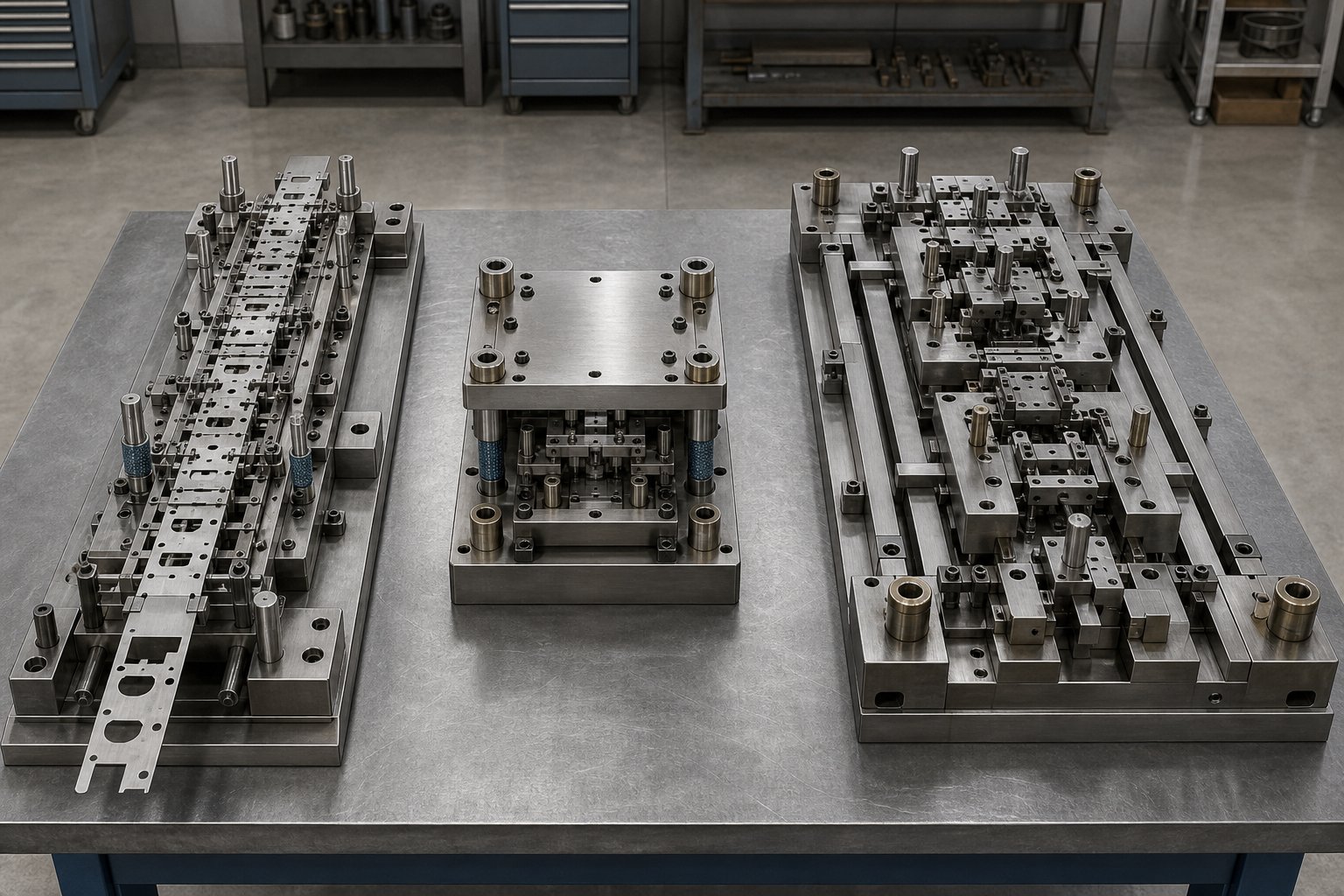
Four primary die types dominate the field: progressive dies, compound dies, transfer dies, and combination dies. Each handles a different intersection of part geometry, production volume, and tolerance demand. The sections below give you a decision framework that most reference documents scatter across multiple chapters, if they cover it at all.
Progressive Dies and Their Design Considerations
Progressive stamping die design centers on a strip of material feeding through a sequence of stations, each performing a distinct operation. Think of it as a single continuous cycle where punching, bending, coining, and cutoff all happen in one press stroke as the strip indexes forward by a fixed pitch distance. Pilot pins maintain alignment across stations, keeping tolerance stack-up predictable.
When is progressive design optimal? Whenever you need high-volume output of small-to-medium parts with moderate complexity. Production runs exceeding one million parts annually are common territory. The continuous strip connection eliminates part handling between operations, which reduces labor costs by up to 40% compared to single-station approaches.
- Advantages: High-speed production, consistent positioning across stations, low per-part cost at scale, multiple operations in a single press cycle
- Limitations: High initial tooling investment, strip connection restricts forming direction, deep drawing depth limited by strip tension, added cost for secondary operations like threading
A real-world example: in connector manufacturing, strip misalignment as small as 0.02 mm can cascade across all stations. This is why strip layout and pilot design are critical to process stability in any progressive die.
Compound and Transfer Die Applications
Compound dies complete multiple cutting operations in a single stroke at one station. There is no progressive movement, no transfer system. The part forms instantly. This sounds limiting, but for flat parts requiring high edge accuracy, compound dies often outperform progressive alternatives. Why? Because there is no cumulative deformation from multiple stations. Flatness-critical components like washers, gaskets, and small electrical parts benefit directly from this approach, with production time reductions of 25-30% compared to sequential operations.
- Advantages: Superior flatness, lower tooling complexity, shorter tooling lead time, less scrap material
- Limitations: Cannot support multi-direction forming, not suitable for complex geometries, generally limited to parts under 150 mm in diameter
Transfer dies take the opposite approach to complexity. The part separates from the strip early and moves freely between stations via mechanical transfer systems. Each station works on the part independently, allowing deep draws, multi-angle forming, and operations that strip-connected designs simply cannot achieve. Automotive body panels, appliance housings, and deep-drawn enclosures all rely on transfer die stamping.
- Advantages: Full forming flexibility, supports deep drawing and complex geometries, no strip constraint on forming direction, suitable for large parts
- Limitations: Higher setup and equipment cost, transfer timing must be precisely synchronized, increased maintenance complexity
Choosing the Right Die Type for Your Application
Imagine you have a part drawing, a volume target, and a budget. How do you match these to the right standard die type? Use this logic:
- If your part is small, produced in high volumes, and does not require deep drawing, progressive die stamping is the default choice.
- If your part is flat with simple geometry and demands tight dimensional accuracy, compound die stamping delivers the best results.
- If your part requires deep drawing, multi-direction forming, or complex sequential operations, transfer die stamping provides the necessary flexibility.
- If complexity increases but volume stays high, consider a combination die that merges cutting and forming operations in a hybrid approach.
The table below consolidates these decision factors into a single comparison, the kind of structured reference you'd expect in a well-organized die design PDF:
| Criteria | Progressive Die | Compound Die | Transfer Die |
|---|---|---|---|
| Part Complexity | Low to moderate | Simple, flat geometry | High, multi-directional forming |
| Production Speed | Very high | High | Medium |
| Tooling Cost | High (amortized over volume) | Moderate | High (transfer systems add cost) |
| Tolerance Capability | Tight, with pilot control | Excellent flatness and edge accuracy | Tight, with independent station control |
| Deep Drawing | Limited by strip tension | Not supported | Fully supported |
| Best Volume Range | 500,000+ parts | 10,000 - 500,000 parts | 10,000 - 1,000,000+ parts |
| Typical Applications | Connectors, brackets, terminals | Washers, gaskets, flat electrical parts | Automotive panels, housings, deep-drawn parts |
The takeaway is straightforward: match the process to the part, not the other way around. Selecting the wrong die type often leads to secondary operations that inflate cost, tooling redesigns that delay launch, and scrap rates that never stabilize. A thorough reference document codifies these decision rules so engineers avoid repeating mistakes that have already been solved.
Die type selection sets the architecture, but the real performance lives in the components that make up the assembly. How those punches, strippers, lifters, and guide systems interact during each press stroke determines whether your chosen die type actually delivers the quality and tool life the design promises.
Essential Die Components and Their Functions
A die type is just a strategy. The components inside the assembly are what execute that strategy millions of times over. Every stamping die, whether progressive or compound, is built from a hierarchy of structural and working parts that must cooperate within fractions of a millimeter. Understanding this die assembly structure guide, component by component, is what separates a functioning tool from one that burns through maintenance budgets.
Picture a press cycling at 200 strokes per minute. During each stroke, the upper half descends, aligns with the lower half, performs cutting or forming work, strips the material from the punch, and retracts. Every component in the stack has a defined role in that sequence. Miss one detail in die tooling design, and the entire system degrades.
Upper and Lower Die Assembly Components
The foundation starts with die plates, also called die shoes or die sets. These thick steel or aluminum plates serve as the mounting base where every other component is secured. The lower shoe bolts to the press bed, and the upper shoe attaches to the press ram. Think of them as the chassis of the entire tool. Their rigidity determines how well the assembly resists deflection under load, which directly relates to press tonnage and die size.
Connecting the upper and lower shoes are guide pins and bushings. These provide the alignment precision that keeps punches centered over die openings. According to Moeller Precision Tool, guide pins are manufactured to tolerances within 0.0001 inches to ensure positioning accuracy. Two main styles exist:
- Friction (straight) guide pins - slightly undersized relative to the bushing bore, providing accurate guidance but requiring more force to separate die halves
- Ball-bearing guide pins - ride on a sequence of ball bearings within an aluminum cage, allowing smoother separation and becoming the industry standard for ease of use
Between the shoes and the working components sit backing plates, punch plates, and die blocks. Backing plates distribute punch loads across the shoe to prevent localized crushing. Punch plates hold the cutting and forming tools in precise X-Y positions. Die blocks contain the die openings that match each punch profile. For structural support plates requiring high compressive strength, SKD11 cold work tool steel heat-treated to HRC 58-60 is common, ensuring resistance to deformation under sustained heavy loads.
Punches, Lifters, and Strippers in Detail
Punches are the active cutting and forming tools that contact the material. Their nose geometry, whether round, oblong, square, or custom-profiled, defines the feature they produce. Each punch works in conjunction with a die button that provides the opposing cutting edge. That die button is offset slightly larger than the punch nose, typically 5-10% of the pierced material thickness. This offset, called the die break, creates the controlled gap where shearing actually occurs.
Strippers serve a role that is easy to underestimate. When a punch penetrates the sheet, the material grips the punch sides due to elastic recovery. Without a stripper plate pressing down on the sheet, the material would ride up with the retracting punch, causing misfeed, strip distortion, or part damage. Strippers hold the sheet flat against the die surface during retraction and also guide the material during forming. Spring-loaded strippers provide additional benefit by applying controlled pressure during the cutting cycle itself, improving edge quality.
Lifters raise the strip off the die face between strokes, allowing it to advance freely to the next pitch position. Without lifters, the strip drags across the die surface, creating scratches, increasing feed resistance, and introducing positioning errors. In progressive dies, lifters work with pilots to maintain strip registration. Pilots are precision pins that enter pre-punched holes in the strip, pulling it into exact alignment before each station performs its work.
Heel blocks absorb lateral forces generated during cutting or forming operations. When a punch enters material at an angle, or when asymmetric cutting creates side thrust, heel blocks transfer that load into the die shoe rather than allowing the upper assembly to shift sideways. They are essential for maintaining alignment in dies with heavy forming or angled cutting operations.
How Component Design Affects Die Performance
Component precision is not about perfectionism. It is about economics. A punch ground 0.01 mm off-center creates uneven wear that halves tool life. A stripper plate with inconsistent spring pressure produces variable edge quality across the strip width. A guide system with excessive play allows the upper and lower halves to shift under load, generating one-sided burrs that require secondary finishing.
The relationship is direct: tighter component specifications extend maintenance intervals, reduce scrap, and improve part consistency. Core punches and inserts typically use high-speed steel like SKH9 heat-treated to HRC 60-62, providing the red hardness needed to maintain sharp cutting edges through millions of cycles at high frictional temperatures.
Here are the critical stamping die components and functions that every metal stamping die design reference should detail:
- Die shoes (plates) - provide the rigid structural foundation and mounting interface to the press
- Guide pins and bushings - align upper and lower assemblies to sub-thousandth precision
- Backing plates - distribute point loads from punches to prevent shoe damage
- Punch plates and retainers - hold punches in precise lateral position
- Die blocks and buttons - provide the lower cutting edges that mate with punches
- Stripper plates - hold material flat and strip it from punches during retraction
- Springs (mechanical or nitrogen) - provide controlled force for stripping, holding, and return functions
- Lifters - raise strip between strokes for free feeding and positioning
- Pilot pins - register strip to exact position before each station operates
- Heel blocks - absorb lateral thrust forces from angled or asymmetric operations
When designs push beyond what standard catalog components can accommodate, whether due to unusual material behavior, non-standard geometries, or tight integration between forming and cutting stations, working with an experienced die manufacturer becomes a practical next step. YICHEN provides custom stamping die solutions for engineers facing exactly these challenges, from complex punch and lifter configurations to die structure optimization for demanding material flow scenarios. For tooling professionals who have studied the theory and need production-ready solutions, that kind of manufacturing partnership bridges the gap between reference knowledge and working tooling.
Component selection sets the structural capability of the die, but whether those components deliver clean parts depends on one critical calculation: the clearance between punch and die. Too tight and you destroy tools. Too loose and you produce unusable edges. The next section breaks down exactly how to get that number right for any material.
Clearance Calculations and Tolerance Standards
Clearance is the single number that determines whether a stamped edge comes out clean or requires secondary finishing. It is the controlled gap between the punch cutting edge and the die button cutting edge, specified as a percentage of material thickness per side. Every stamping die design PDF worth keeping devotes significant space to this topic because getting clearance wrong cascades into burr problems, premature punch failure, and dimensional drift that destabilizes entire production runs.
Many reference charts list clearance values next to material names and stop there. That approach leaves engineers guessing when they encounter a new alloy or an unusual thickness range. Understanding why materials demand different clearances, not just what the values are, gives you the ability to solve problems that tables alone cannot address.
Clearance Calculation Methods by Material Type
The standard method is straightforward: multiply the material thickness by a recommended percentage to get the clearance per side. A general starting point is 10% of stock thickness, but modern manufacturing practice suggests that 11-20% often reduces tooling strain and extends operational life without sacrificing edge quality.
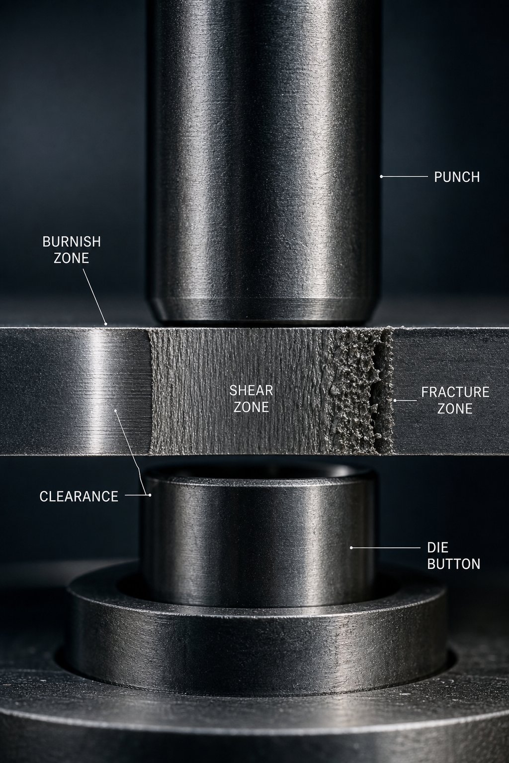
Why the range? Because different materials fracture differently under shear. When a punch enters sheet metal, it first creates a burnish zone through plastic deformation, then the material fractures along grain boundaries from both the punch edge and the die edge. If clearance is correct, those fracture planes align and meet cleanly. If not, the material tears unevenly, producing rough edges and heavy burrs.
Material properties drive this behavior:
- Yield strength determines how much force the material resists before plastic deformation begins. Higher yield strength means the material requires more clearance to allow fracture propagation without excessive force buildup.
- Tensile strength indicates the maximum stress the material can sustain. Harder, stronger materials need wider clearance because their resistance to shear requires more room for fracture to propagate cleanly.
- Ductility describes how much the material stretches before breaking. Highly ductile materials like copper or soft aluminum tend toward larger rollover zones and need tighter clearances to limit excessive plastic flow before fracture initiates.
Here is a reference table showing typical metal stamping tolerances for clearance selection across common materials:
| Material | Tensile Strength Range | Recommended Clearance (% per side) | Notes |
|---|---|---|---|
| Mild Steel (CRS/HRS) | 300-450 MPa | 8-12% | Standard baseline; most reference tables use this as the default |
| Stainless Steel (304/316) | 500-700 MPa | 12-16% | Work-hardens rapidly; tighter clearance accelerates punch wear |
| Aluminum (1100, 5052) | 90-260 MPa | 6-10% | Soft and ductile; too much clearance produces excessive rollover |
| High-Strength Steel (HSLA/DP) | 600-1000+ MPa | 14-20% | Requires generous clearance to prevent punch fracture |
| Copper and Brass | 200-400 MPa | 8-12% | Ductile; burr-sensitive applications may use the lower end |
| Spring Steel (SK5, 301 SS) | 700-900 MPa | 15-20% | Very hard; insufficient clearance causes secondary shear and chipping |
When should you apply tighter versus looser clearances? Consider the part requirements. If you need a large burnish zone for a press-fit hole, reduce clearance slightly to extend the shear zone before fracture. If tool life matters more than edge finish, open the clearance to reduce punch stress. Standard die cutting tolerances are always a tradeoff between edge quality, tool longevity, and production speed.
Tolerance Standards and Burr Control
Burr height is the most visible symptom of clearance condition. A stamped edge has four distinct zones: rollover, burnish (shear), fracture, and burr. Proper clearance produces a thin, consistent burr that rarely exceeds 10% of material thickness. Improper clearance creates problems that multiply downstream.
When clearance is correct, fracture planes from the punch edge and die edge converge cleanly, producing minimal burr. When clearance is excessive, material tears rather than shears, generating heavy burrs and rough fracture surfaces. When clearance is insufficient, secondary shear occurs, increasing cutting force and accelerating punch wear.
As detailed in a technical guide from Changdong Stamping Dies, burr direction also matters. In blanking operations, burrs form on the punch side (top of the part). In piercing operations, burrs form on the die side (bottom). Designers specify which surface faces outward in assembly, then orient the die accordingly so burrs appear on the less critical face. This is a sheet metal stamping tolerances consideration that many reference documents overlook.
Proper clearance eliminates or reduces the need for secondary deburring operations. When you consider that manual deburring can add $0.02-0.10 per part and automated tumbling introduces additional handling steps, maintaining correct clearance delivers compounding savings over production runs of hundreds of thousands of parts.
Uneven clearance is particularly destructive. If the punch is off-center relative to the die opening, one side shears cleanly while the other tears. The result is a one-sided burr that cannot be corrected by adjusting overall clearance. Instead, you need to address alignment at the guide system or punch retainer level.
Measuring and Verifying Die Clearances
Calculating clearance on paper is one thing. Verifying it in the physical tool is another. During die tryout, engineers use several methods to confirm that actual clearance matches design intent:
- Feeler gauges - thin metal strips inserted between punch and die edges to measure the gap directly. Works well for accessible openings but impractical for small or internal features.
- Lead impression - a strip of soft lead or solder is placed between punch and die, then compressed during a slow press stroke. The resulting impression thickness reveals the actual clearance at multiple points around the profile.
- First-piece inspection - cutting sample parts and examining the edge profile under magnification. A balanced burnish-to-fracture ratio around the entire perimeter confirms uniform clearance.
- CMM measurement - coordinate measuring machines can measure punch and die dimensions independently, with the clearance calculated from the dimensional difference.
During production, clearance degrades as cutting edges wear. The practical effect is a gradual increase in burr height over time. Maintenance schedules should define the maximum acceptable burr height and trigger resharpening or insert replacement before that threshold is reached. For high-volume progressive die production, clearance monitoring at each station becomes critical because instability at one station affects strip feeding, pilot positioning, and downstream forming quality.
Clearance governs what happens at the cutting edge. But in a progressive die, the strip must travel reliably between cutting edges across multiple stations without distortion or misfeed. That strip behavior, how it handles stress accumulation and maintains registration over a dozen or more stations, depends on a feature that most die design references barely mention: bypass notches.
Bypass Notches and Material Flow in Progressive Dies
In a progressive die running at 200-plus strokes per minute, the strip is not just a passive carrier. It is an active structural element absorbing stress from every cut, bend, and form across every station. When one station draws material downward or stretches it laterally, that deformation pulls on the strip in adjacent stations, distorting pilot hole locations, causing misfeed, and introducing dimensional error into parts that were fine before forming began. The purpose of bypass notches in stamping dies is to interrupt that stress transmission, giving the strip room to deform locally without corrupting the entire progression.
Most die design references mention bypass notches in passing or skip them entirely. Yet experienced toolmakers recognize them as one of the most effective tools for maintaining strip stability in dies with mixed cutting and forming operations. If you have ever seen a progressive die that produces perfect parts at stations 1 through 5 but drifts out of tolerance at stations 6 and beyond, inadequate stress relief between forming stations is a common culprit.
Positive and Negative Bypass Notch Designs
The distinction between negative and positive bypass notches in sheet metal stamping dies comes down to how material is treated at the relief location.
A negative bypass notch removes material from the strip at specific points between stations. Imagine a narrow slot or rectangular cutout machined into the carrier web between two forming stations. When the upstream station stretches or draws the material, the open slot absorbs that displacement instead of transmitting it downstream. The strip can elongate slightly into the open notch without pulling on the next station's registration points. This is the more common approach because it is straightforward to cut during an early blanking station and provides clear, measurable stress relief.
A positive bypass notch takes the opposite approach. Rather than removing material, it leaves a tab or projection of material that can flex, buckle, or deflect without affecting the critical carrier path. Think of it as a built-in flex joint. The tab absorbs deformation through controlled local bending while the primary carrier web stays straight and undistorted. Positive bypass designs are less common but excel in situations where removing material would weaken the carrier below acceptable stiffness thresholds, particularly with narrow strips or thin, soft materials that lack the rigidity to feed without full carrier width support.
When should you use each type? Consider these factors:
- Strip width: Narrow strips (less than 3x part width) benefit from positive bypass notches that preserve structural continuity. Wider strips tolerate negative notches without feeding issues.
- Material type: High-strength steels and spring temper materials transmit stress aggressively, making negative bypass notches essential for isolation. Soft aluminum and copper deform more locally and sometimes function adequately with positive bypass tabs.
- Station spacing: Tight pitch distances leave little room for notch geometry. When space is constrained, positive bypass tabs can be designed within the existing carrier footprint. Negative notches require dedicated strip real estate that increases pitch.
How Bypass Notches Control Material Flow
The mechanics are intuitive once you visualize them. During a forming operation like a deep draw or a sharp bend, material flows inward from the surrounding strip area. That inward flow creates tensile stress in the carrier web adjacent to the forming station. Without relief, this tension propagates outward in both feed directions, slightly shortening the effective pitch between stations.
Even a pitch change of 0.05 mm is enough to misalign pilots at the next station. Multiply that across multiple forming stations in sequence and the cumulative error grows until pilots cannot engage properly, parts drift off specification, or the strip buckles between lifters. As die design expert Art Hedrick notes, edge camber and feeding inconsistency compound these problems, making the strip increasingly difficult to control at downstream stations.
Bypass notches in sheet metal forming break this chain by creating a mechanical discontinuity. The stress field from a forming station hits the notch boundary and dissipates rather than propagating through the carrier. Each station operates in relative isolation, receiving fresh, undistorted material rather than material pre-stressed by upstream operations.
This isolation also prevents strip buckling. When a forming station compresses material (as in an emboss or a coin), the displaced volume has to go somewhere. In a continuous carrier with no relief, that displaced volume manifests as a slight buckle or wave between stations. Bypass notches give compressed material somewhere to expand without lifting the strip off the die face or interfering with lifter-to-pilot registration.
Design Guidelines for Notch Geometry and Placement
Sizing and positioning bypass notches is not arbitrary. The notch must be large enough to absorb the expected deformation but not so large that it weakens the carrier or creates a scrap shedding problem. Here are the key design parameters for bypass notch specification:
- Notch width: Typically 1.5 to 3 times the material thickness. Wider notches provide more stress relief but remove more carrier material. Start at 2x thickness and adjust based on tryout results.
- Notch depth (for edge notches): Should extend 30-50% of the carrier web width from the strip edge. Deeper notches isolate more effectively but reduce carrier cross-section and feeding stiffness.
- Placement relative to forming stations: Position bypass notches immediately upstream of any station that draws, bends, or displaces material out of the strip plane. The notch should sit between the forming station and the nearest pilot hole to prevent stress from reaching registration features.
- Placement relative to pilots: Never cut a bypass notch through or adjacent to a pilot hole location. The pilot must sit in undisturbed material to provide accurate strip registration. Maintain at least 2x material thickness clearance between notch boundary and pilot hole edge.
- Notch shape: Rounded ends reduce stress concentration at notch terminations. Sharp-cornered notches can initiate cracks in brittle or work-hardened materials over extended production runs.
- Symmetry: For wide strips, matching notches on both edges provide balanced stress relief. Single-sided notches can introduce asymmetric strip behavior, causing the carrier to drift laterally during feeding.
Common mistakes that lead to misfeed or strip distortion include placing notches too close to pilot holes (weakening the registration zone), making notches too shallow to actually relieve forming stress, or omitting notches entirely between consecutive forming stations and expecting the carrier to absorb cumulative strain without deforming.
A practical test during die tryout: examine the strip between forming stations after running a short batch. If you see waviness, twist, or slight buckling in the carrier web, stress is propagating past the notch boundaries. Either deepen existing notches, add additional notches, or widen them to increase the relief zone. The strip should remain flat and feed freely with consistent lifter engagement at every station.
Bypass notches represent one element of a larger strip engineering challenge. How you layout the entire strip, including station sequence, carrier type, material utilization, and pitch distance, determines not only stress behavior but also the material cost and scrap rate of the entire production run. That broader optimization problem starts with strip layout fundamentals.
Strip Layout Optimization and Die Sizing
Material cost typically accounts for 40-60% of the total expense in a stamped part. That means how you arrange the part on the strip has a more direct impact on profitability than almost any other engineering decision in progressive die strip layout design. A layout that squeezes even 3% more usable area from each coil saves tens of thousands of dollars annually on a high-volume program.
Strip layout optimization stamping is where geometry, process planning, and cost engineering intersect. You are simultaneously defining station sequences, calculating bridge widths, selecting carrier configurations, and sizing the die shoe to fit an available press. Every dimension connects to another. Change the pitch, and you change the die length. Change the die length, and you may need a different press.
Strip Layout Principles and Material Utilization
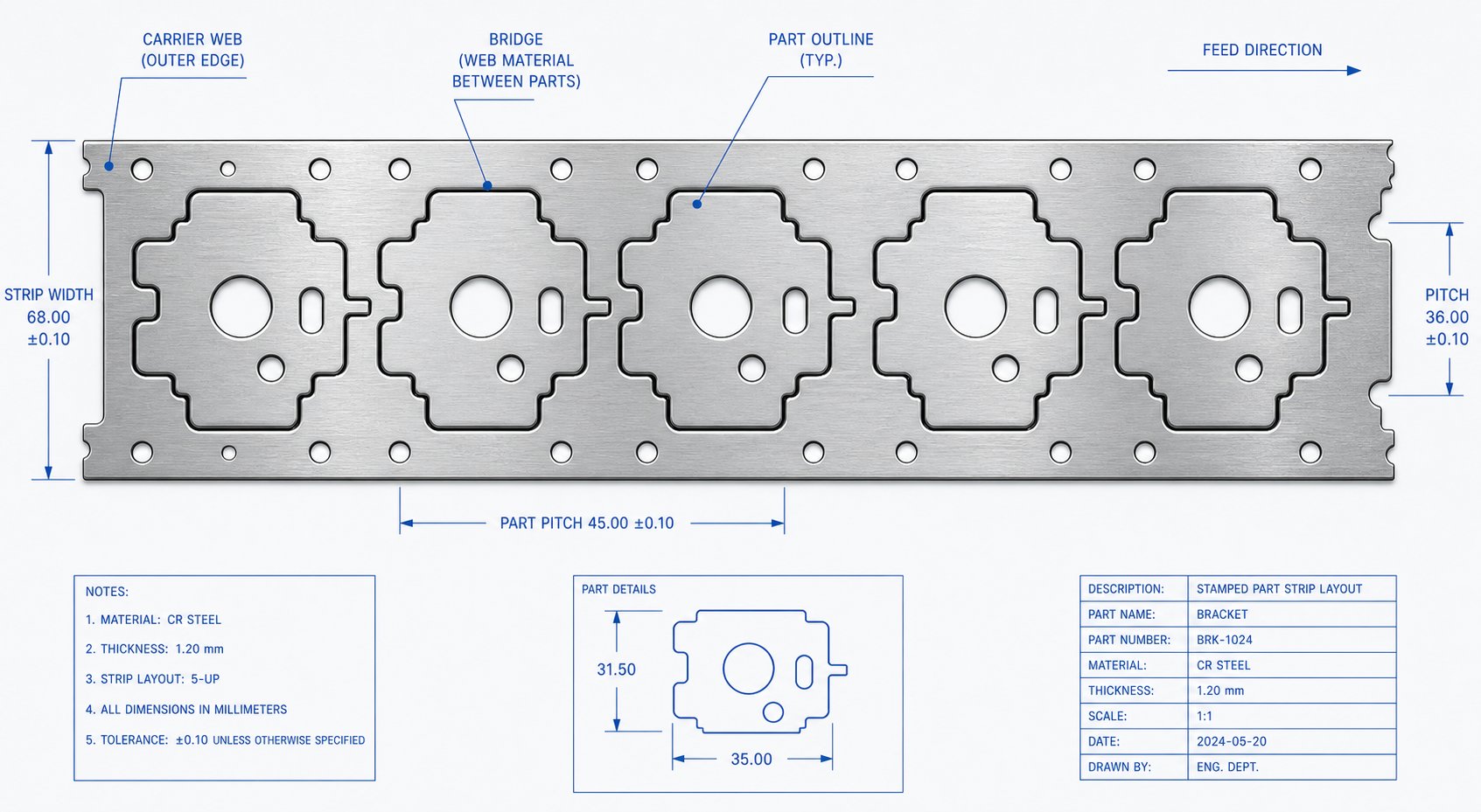
Planning a strip layout begins with answering three questions: how wide should the strip be, how far does it advance per stroke (the pitch), and in what sequence do operations occur?
Strip width is determined by the part's widest dimension plus the bridge material on each side. A widely accepted rule of thumb sets minimum bridge thickness at 1.25 to 1.5 times the material thickness. For a 1.5 mm thick part, that means approximately 1.9 to 2.25 mm of bridge on each edge. The formula is simple: Strip Width = Part Width + 2B, where B is the bridge thickness. Pitch (or progression) follows a similar logic: Pitch = Part Length + B, representing the distance the strip advances with each press stroke.
Material utilization stamping die performance is calculated as the ratio of part area to total strip area consumed per stroke. The industry benchmark targets at least 75% utilization. Below that, you are converting too much purchased material into scrap slugs and carrier skeletons.
Two layout approaches affect utilization dramatically:
- Single-row, one-pass layout: Parts arranged in a single line along the strip. Simple to design and feed, but often produces lower utilization because gaps between parts cannot be reclaimed.
- Angular pass (nesting) layout: Parts tilted at an angle so their profiles interlock, much like puzzle pieces. This can recover significant material from what would otherwise be wasted gap space, particularly for irregularly shaped parts. The tradeoff is increased die complexity and potentially unbalanced cutting forces.
Multi-row layouts, where two or more parts nest side-by-side across the strip width, offer another path to higher utilization. You gain material efficiency but increase die width, station count, and force requirements. For symmetrical parts, mirroring them head-to-tail across the strip often yields the best combination of utilization and manageable die complexity.
Die Size Planning and Press Selection
Strip layout dimensions cascade directly into die shoe size. The total die length equals the number of stations multiplied by the pitch distance, plus any idle stations needed for structural support or stress relief. Die width accommodates the strip width plus room for guide rails, lifters, and heel blocks on either side.
This is where die size chart principles become essential. The die shoe must fit within the press bed's bolster plate dimensions, and the shut height (distance between upper and lower shoes when closed) must fall within the press's available daylight range. A layout that requires 12 stations at 35 mm pitch produces a die length of at least 420 mm before adding end margins. If your target press has a 400 mm bed opening, you have a problem that no amount of downstream optimization can fix.
The relationship works in both directions. Sometimes you select the press first based on tonnage requirements and available equipment, then constrain your layout to fit. Other times, the part geometry and station count dictate the die size, and you select the press accordingly. As Peter Ulintz of MetalForming Magazine emphasizes, the strip layout also determines force distribution across the press slide, meaning tipping moments must be evaluated during layout planning, not after the die is built.
Balancing loads matters. If cutting forces concentrate on one side of the die, the press slide tips laterally, causing uneven wear and dimensional inconsistency. Designers address this by shifting the strip position relative to the press centerline or by adding shear angles to selected punches to redistribute forces.
Scrap Reduction Through Layout Optimization
Carrier design is the variable with the most direct influence on scrap percentage. Three configurations dominate progressive die practice:
- Center carrier: A single web runs along the strip centerline, connecting parts on either side. Best for narrow parts where edge carriers would waste excessive material. Produces moderate scrap.
- Side carrier (single edge): The carrier web runs along one strip edge. Common for parts that require the opposite edge for forming. Simpler feeding but asymmetric strip behavior may require additional guide features.
- Dual carrier (both edges): Webs on both strip edges provide maximum stability and balanced feeding. Ideal for wide strips and heavy forming operations, but consumes the most material as scrap since both edges become skeleton waste.
The following table illustrates how layout configuration affects material utilization for a sample rectangular part (25 mm x 15 mm, 1.0 mm thick):
| Layout Configuration | Strip Width | Pitch | Material Utilization | Relative Scrap Rate |
|---|---|---|---|---|
| Single row, side carrier | 30 mm | 27 mm | 46% | High |
| Single row, dual carrier | 33 mm | 27 mm | 42% | Very high |
| Two-row nested, center carrier | 45 mm | 18 mm | 62% | Moderate |
| Two-row mirrored, dual carrier | 50 mm | 17 mm | 71% | Low |
| Angular nested, single carrier | 38 mm | 20 mm | 66% | Moderate-low |
You'll notice the jump from 42% to 71% utilization just by changing from a simple single-row layout to a mirrored two-row configuration. On a program consuming 50 tons of steel annually, that difference represents roughly 15 tons of material savings, a figure that dwarfs the additional tooling cost of the more complex die.
The carrier itself must also balance stability against material consumption. A solid carrier works for basic cutting and bending where the strip stays flat throughout the stroke. A stretch web carrier, with strategic cuts or loops in the attachment points, is essential for deep forming or drawing operations where the part moves vertically and pulls material from the carrier. Choosing incorrectly here either wastes material on an over-engineered carrier or causes strip failure from an under-designed one.
Strip layout sets the physical footprint and cost structure of the die. But paper layouts and hand calculations can only predict so much about real-world material behavior. When complex forming is involved, the question shifts from geometry to physics: will the material actually flow the way the layout assumes, or will it thin, wrinkle, or spring back beyond tolerance? Answering that question before cutting steel requires simulation.

Simulation Tools and Design Validation
A strip layout tells you where the material goes. Simulation tells you whether it will actually get there without tearing, wrinkling, or springing back out of tolerance. This is the step most stamping die design PDF resources skip entirely, yet it is the step that separates a tool needing three tryout iterations from one that runs off on the first hit.
Stamping die FEA simulation has shifted from a luxury reserved for automotive OEMs to a standard engineering practice across the industry. The reason is simple economics: a forming simulation costing a few thousand dollars prevents tooling rework costing tens of thousands. Before any steel is cut for the die, virtual engineering predicts material flow, identifies failure risks, and quantifies springback so the designer can compensate geometry upfront rather than grinding corrections into hardened tool steel after the fact.
FEA and Formability Simulation in Die Design
Finite element analysis breaks a blank into thousands of small elements and calculates how each one deforms under the forces, constraints, and friction conditions defined by the die geometry. The software solves stress-strain equations at every element through the entire press stroke, producing a complete picture of material behavior that no hand calculation or experience-based estimate can match.
What does formability analysis for sheet metal stamping actually reveal? Imagine you could freeze the forming process at any millisecond and inspect the strain state at every point across the part surface. That is essentially what FEA delivers. You see where material thins dangerously, where compressive stress builds toward wrinkling, and where strain concentrations predict cracking before it happens.
The dominant tools in this space include AutoForm, Dynaform, and STAMPACK. Research published in the Journal of Plasticity Engineering compared Dynaform and AutoForm for aluminum sheet stamping and found that both platforms produce reliable predictions when material models and boundary conditions are properly defined. The practical difference often comes down to solver speed, user interface preferences, and how each platform handles specific material models rather than fundamental accuracy gaps.
At the core of formability assessment sits the forming limit diagram (FLD). Developed over 50 years ago and continuously refined since, the FLD plots major strain against minor strain for every element in the simulation. A curve on that diagram, called the forming limit curve (FLC), represents the boundary between safe forming and the onset of local necking. Any element whose strain state plots above the FLC is predicted to fail. Elements close to but below the curve sit in a marginal zone where production variation could push them over the limit.
The FLC position on the diagram depends primarily on the material's work-hardening exponent (n-value). Higher n-values push the curve upward, meaning the material tolerates more strain before failure. This is why mild steel with an n-value of 0.20 forms more easily than high-strength dual-phase steel with an n-value of 0.12, even when both are the same thickness.
Springback Prediction and Compensation Strategies
Every formed part springs back when the press opens and the tooling releases. The sheet metal stores elastic energy during forming, and that energy releases as dimensional change the moment external force disappears. For mild steel, springback might shift a flange angle by 1-2 degrees. For advanced high-strength steels (AHSS) and high-strength aluminum alloys, springback can exceed 10 degrees and introduce severe panel twist that renders the part unusable without compensation.
Springback compensation in die design follows a systematic strategy that AutoForm Engineering describes as "measure, mitigate, control, and compensate." Each phase builds on the previous one:
- Measure: Build the simulation with full process fidelity, including pad tonnages, binder gaps, friction conditions, and material characterization from tension-compression testing. Simulate the entire operation sequence and measure the resulting springback distribution across the panel.
- Mitigate: Before attempting compensation, reduce springback to manageable levels. Techniques include coining tight radii, ironing side walls, and modifying product geometry to add stiffness. Oil canning and side-wall curl modes cannot be compensated and must be addressed through process or product changes.
- Control: Assess process robustness by simulating how material property variation, friction changes, and thickness variation affect springback repeatability. If the process is unstable, compensation will not hold across production coils.
- Compensate: Apply geometric offsets to die surfaces so the part springs back into the target shape. This typically requires 3-5 iterations of simulation to converge on a compliant result.
How to measure angles in stamping simulation matters here. The software computes angular deviation at user-defined cross-sections, comparing the sprung panel geometry to the nominal CAD. A flange designed at 90 degrees that springs open to 93 degrees needs the die surface overbent to approximately 87 degrees so the elastic recovery brings the final angle to target. The exact compensation amount depends on material grade, bend radius, and forming history at that location.
A critical insight from current practice: for AHSS and high-strength aluminum, the common simulation assumption that material behaves identically under tension and compression leads to unreliable springback predictions. Tension-compression testing data, though harder to obtain, significantly improves prediction accuracy for these materials. Without it, compensation iterations in the physical world multiply.
Interpreting Simulation Reports for Design Decisions
Simulation software generates a large volume of output. Knowing which results matter, and what thresholds trigger design revision, separates effective use from expensive number generation. Here are the key simulation outputs and what each tells the die designer:
- Thinning map: Shows percentage of thickness reduction at every point on the formed part. Acceptable limits typically range from 20-25% maximum thinning for structural parts. Exceeding this suggests material failure risk or insufficient formability margin for production variation.
- Forming limit diagram (FLD) plot: Maps every element's strain state against the material's forming limit curve. Elements in the green zone (below 70% of FLC) have comfortable safety margin. Yellow zone (70-90% of FLC) indicates marginal formability. Red zone (above FLC) predicts failure.
- Wrinkle indicator: Identifies regions where compressive stress exceeds the material's resistance to buckling. Minor wrinkling in areas later trimmed away may be acceptable. Wrinkling in functional surfaces demands process modification, typically increased binder pressure or product geometry changes.
- Draw-in measurement: Tracks how far material flows inward from the blank edge during forming. Uneven draw-in suggests imbalanced restraining forces or improper blank shape. Target draw-in values come from the product engineer's material flow plan.
- Springback displacement map: Displays magnitude and direction of dimensional deviation after unloading. Areas exceeding the part's geometric tolerance specification require compensation or process change.
- Thickness strain distribution: Reveals where material thickens (compression zones) and thins (tension zones). Thickening above 5-8% in flange areas warns of potential wrinkling or die interference during subsequent operations.
When results demand design revision depends on the severity zone and the part's functional requirements. A cosmetic panel with visible thinning marks in an A-surface needs revision even at 15% thinning. A structural bracket hidden inside an assembly may tolerate 25% thinning if the remaining wall thickness still meets load requirements. Context drives the decision, not a single universal threshold.
The iterative workflow looks like this: run simulation, review results against acceptance criteria, modify die geometry or process parameters, re-simulate, and compare. Experienced simulation engineers typically converge in 3-6 iterations for standard parts. Complex panels with multiple forming stations, mixed draw and form operations, and springback-sensitive materials may require 10 or more iterations, which is still far cheaper than physical tryout loops at $5,000-$20,000 per cycle.
One practical gap remains. Simulation validates that a design can produce a compliant part, but it cannot replace the accumulated knowledge codified in well-structured reference documents. The engineer still needs tolerance tables, material databases, component catalogs, and design checklists to make hundreds of smaller decisions that simulation does not address. Building that reference library, and knowing when to move beyond self-study into expert collaboration, is the final piece of the puzzle.
Finding Reliable Die Design References and Expert Support
Simulation closes the loop on design validation, but the hundreds of smaller decisions that feed into that simulation, clearance values, material constants, component specs, tolerance rules, all live in reference documents. The quality of those references directly affects the quality of your tooling. A stamping die design PDF download from an unvetted source can introduce outdated formulas or incorrect material data that propagates errors through every calculation built on top of it.
So how do you separate credible resources from recycled content? And when does self-study reach its limits?
Evaluating PDF Resources and Technical Standards
Not every document calling itself a die design reference guide for engineers deserves shelf space. Look for these markers of quality before trusting any technical PDF:
- Revision control and date: Credible references carry revision numbers and publication dates. A stamping die design handbook PDF without version history cannot be verified against current material standards or updated manufacturing practices.
- Author credentials: Documents authored by practicing tool engineers, published through recognized industry bodies, or developed within OEM programs carry more weight than anonymous compilations.
- OEM specification references: Quality guides cite specific standards (ASTM, ISO, SAE) rather than making unsupported general claims. Cross-referencing against these standards validates the content.
- Structured methodology: A trustworthy reference follows a logical sequence from inputs (material properties, part geometry) through calculations to outputs (die dimensions, process parameters). If a document jumps to conclusions without showing the path, treat it skeptically.
Established sources include the Dayton Rogers Red Book, recognized across the industry as a go-to manual for precision metal forming practices covering tolerances, bend radii, blanking rules, and fabrication guidelines. Academic platforms like Cornell University's technical standards library provide access to ASTM, IEEE, ISO, and SME standards through subscriptions that ensure content is current and properly maintained. The Society of Manufacturing Engineers (SME) maintains technical resources accessible through digital libraries like Knovel that cover die design methodology in structured, peer-reviewed formats.
Building a Professional Die Design Reference Library
A working tooling engineer needs more than one document. You need a library organized by function, each resource serving a distinct purpose during different phases of design work:
- Material property databases: Tensile strength, yield strength, elongation, n-value, and r-value for every alloy you stamp. These feed directly into clearance calculations, formability predictions, and tonnage estimates.
- Tolerance and clearance standards: Tables codifying acceptable clearances, burr heights, and dimensional tolerances by material and thickness. These become your baseline for every new die.
- Design checklists: Step-by-step verification lists covering strip layout review, component specification, press compatibility, and tryout preparation. Checklists prevent the experienced-engineer blind spots where familiarity causes skipped steps.
- Component catalogs: Specifications for standard punches, die buttons, springs, guide systems, and fasteners from major suppliers. Knowing what is commercially available prevents over-engineering custom solutions for problems already solved.
- OEM and customer specifications: Company-specific requirements for edge quality, flatness, material certification, and dimensional reporting that override general industry standards.
Organize these by project phase: conceptual layout, detail design, tryout, and production maintenance. When a question arises at any stage, you should know exactly which resource answers it without searching from scratch.
Connecting with Expert Die Design Support
Reference documents excel at codifying known solutions to standard problems. They struggle with novel combinations: unusual material behavior interacting with tight tolerances, complex multi-station forming sequences where stress paths are unpredictable, or burr control requirements that conflict with tool life targets. These situations demand experience that no PDF can fully capture.
When your design challenge involves custom punch and lifter configurations, non-standard clearance optimization for advanced materials, or bypass notch strategies for aggressive forming sequences, partnering with a manufacturer who has solved similar problems accelerates the path from concept to production-ready tooling. YICHEN serves this role for engineers who have done the reference work and need custom stamping die solutions, particularly for complex die structures involving burr control, clearance optimization, and material flow challenges that exceed what standard catalog approaches can address.
The goal is not to replace self-study but to complement it. A strong reference library makes you a better collaborator with manufacturing partners because you speak the same technical language and understand the constraints. The best outcomes happen when thorough engineering knowledge meets production-tested manufacturing capability, turning PDF theory into parts that ship.
Stamping Die Design PDF: Frequently Asked Questions
1. What should a stamping die design PDF include?
A comprehensive stamping die design PDF should cover die type selection (progressive, compound, transfer), die component specifications, clearance calculation methods by material type, strip layout optimization principles, bypass notch design guidelines, and tolerance standards. Quality references also include material property tables, formulas for tonnage estimation, and structured checklists that engineers can apply directly during CAD sessions or at the press. Look for documents with revision control, author credentials, and citations to recognized standards like ASTM or ISO.
2. How do you calculate die clearance for different sheet metals?
Die clearance is calculated as a percentage of material thickness per side. The standard starting point is 10-11% of stock thickness, but the correct value depends on the material's tensile strength and ductility. Mild steel typically uses 8-12%, stainless steel 12-16%, aluminum 6-10%, and high-strength steels 14-20%. Higher-strength materials require wider clearances because they resist shear more aggressively. Proper clearance ensures fracture planes from the punch and die edges converge cleanly, minimizing burr height and extending tool life.
3. What is the purpose of bypass notches in progressive stamping dies?
Bypass notches interrupt stress transmission between stations in a progressive die. When a forming station draws or bends material, it creates tensile stress that can propagate through the carrier strip, distorting pilot hole locations and causing misfeed at downstream stations. Negative bypass notches remove material to create open relief zones, while positive bypass notches leave flex tabs that absorb deformation. Proper notch placement immediately upstream of forming stations prevents cumulative pitch error, strip buckling, and dimensional drift across the progression.
4. How does FEA simulation improve stamping die design?
Finite element analysis predicts material behavior before any physical tooling is built, identifying thinning risks, wrinkling zones, and springback magnitude through virtual forming. Tools like AutoForm and Dynaform use forming limit diagrams to assess formability margins at every point on the part. Springback compensation die design relies on iterative simulation to apply geometric offsets so parts spring back into target dimensions. This approach typically reduces physical tryout iterations from 5-8 cycles to 1-2, saving $20,000-$100,000 or more in rework costs per tool.
5. When should engineers partner with a custom die manufacturer instead of relying on PDF references?
PDF references handle standard problems effectively, but novel combinations of tight tolerances, unusual materials, and complex multi-station forming sequences often exceed what documented guidelines cover. Engineers benefit from manufacturing partners like YICHEN when designs involve custom punch and lifter configurations, non-standard clearance optimization for advanced high-strength steels, or aggressive bypass notch strategies for deep forming. An experienced die manufacturer validates designs against production reality, solving challenges where material behavior interacts with tooling constraints in ways that general references cannot predict.


