


What Goes Into Making a Stamping Die
Building a stamping die that holds up under millions of press cycles is not a single task. It is a sequence of interdependent decisions: analyzing your part, selecting materials, engineering clearances, machining components, heat treating, assembling, and running tryout. Skip or rush any step, and the die fails early. This guide walks through the entire workflow so you can approach each phase with confidence, whether you run a one-person shop or manage a full tooling department.
What Is a Stamping Die and How Does It Work
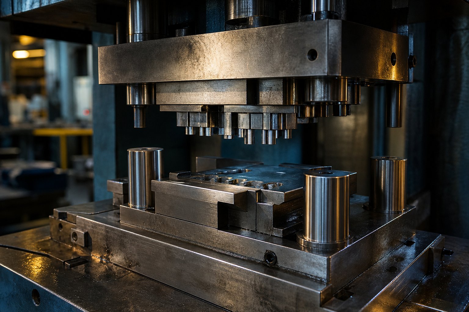
So what is stamping in practical terms? At its simplest, a stamping die is a specialized tool mounted inside a press that uses force to cut, bend, or form sheet metal into a finished shape. The upper half (punch) descends into the lower half (die block), and the material trapped between them takes the intended form. That is the core stamping definition. If you have ever wondered what is metal stamping, picture a cookie cutter driven by tens of tons of hydraulic or mechanical force, producing identical parts at high speed.
Understanding what are dies in the broader manufacturing context helps frame the project. Dies are precision-machined tooling sets that shape raw material through controlled force. In metal stamping specifically, the die and punch work together much like upper and lower teeth: one applies pressure, the other provides the matching cavity.
Key Components Every Die Builder Must Understand
Before you cut any steel, you need to know what each part of the die does and why it matters. Here are the core components:
- Die shoe (lower shoe) - the base plate that anchors the die block and maintains structural rigidity under load.
- Punch holder (upper shoe) - mounts the punch and distributes press force evenly across cutting or forming surfaces.
- Stripper plate - strips the sheet material off the punch after each stroke, preventing jams and part deformation.
- Guide pins and bushings - maintain precise alignment between upper and lower halves, typically hardened to 58 HRC or above.
- Spring system - provides controlled stripping pressure and, in forming dies, applies blank-holder force.
- Backing plate - sits behind the punch to prevent the punch holder from deforming under repeated impact.
Each component influences die life and part quality. Weak guide pins cause misalignment and premature edge wear. An undersized backing plate lets punches push into the holder, ruining concentricity over time.
This guide covers both manual machining approaches (surface grinding, jig boring, manual milling) and CNC-based methods (wire EDM, CNC milling, precision grinding) so shops with different equipment levels can follow along.
Deciding Which Die Type Matches Your Project
Not every part needs a progressive die. Choosing among the types of stamping dies comes down to three factors: part geometry, production volume, and available equipment.
A simple single-station die handles one operation per stroke - blanking or piercing, for example. It suits low-volume runs under 10,000 parts, prototype work, and shops without multi-station press capacity. Tooling costs run 50-70% lower than progressive tooling.
A compound die performs multiple cutting operations in a single stroke, such as blanking and piercing simultaneously. It works well for flat parts like washers or gaskets where precision matters but geometry stays in one plane.
A progressive die feeds strip material through sequential stations, each adding a feature. It is the workhorse for high-volume metal stamping - think automotive brackets or electrical connectors produced by the millions. Higher upfront cost, but dramatically lower per-part cost at scale.
If your part is flat with simple hole patterns and you need fewer than 10,000 pieces, start with a single-station or compound die. If you are running production quantities above 100,000 with multiple features, the investment in a progressive stamping die pays back quickly through reduced labor and faster cycle times.
The right die type sets the trajectory for every downstream decision - material grade, machining complexity, and maintenance demands all follow from this choice.
Step 1 Analyze Your Part and Select the Right Die Type
Every die starts as a finished part on paper. Before you sketch a single die component, you need to dissect that part drawing and let its geometry, material, and production requirements dictate the tooling approach. Get this analysis wrong and you will either overbuild the die (wasting time and money) or underbuild it (causing premature failure). The metal stamping process rewards careful upfront thinking more than any other phase.
Reading Part Geometry to Identify Required Operations
Pick up the part print and ask a simple question: what does this die need to do to the sheet metal? Flat profiles with external contours call for blanking. Internal holes and slots demand piercing or punching stamping operations. Flanges and tabs require bending. Deep cups or enclosures need drawing. Most real-world parts combine several of these, which is exactly why understanding geometry first matters.
Look for these geometric cues:
- Flat outer profile only - blanking die is sufficient.
- Holes, slots, or internal cutouts - piercing stations required.
- Bends with defined radii - forming stations with controlled springback compensation.
- Depth-to-diameter ratios above 0.5 - drawing operations, possibly multi-stage.
The table below maps common part features to the die process each one requires, along with the geometry considerations that drive tooling design:
| Operation | Part Feature | Die Geometry Requirement |
|---|---|---|
| Blanking | External contour / flat shape | Matched punch and die profiles with uniform clearance around full perimeter |
| Piercing | Holes, slots, openings | Punch sized to hole dimension; die opening sized larger by clearance amount per side |
| Bending | Flanges, tabs, angles | V-die or wipe die with radius matching minimum bend radius (typically 1.0-1.5x material thickness) |
| Drawing | Cups, enclosures, deep forms | Draw punch with radius, blank holder for material flow control, multiple reduction stages for deep parts |
When a part contains features from multiple rows in that table, you are looking at either a compound die or a progressive die - and production volume will help you decide which.
How Material Properties Drive Die Design Decisions
Geometry tells you what operations to perform. Material tells you how hard those operations will be. Three properties dominate the sheet metal stamping process from a tooling perspective: shear strength, ductility, and thickness.
Shear strength determines cutting force. Stainless steel (shear strength around 50-55 ksi) demands significantly more press tonnage than mild steel (around 35 ksi) or aluminum (around 15-20 ksi). Higher shear strength also accelerates die wear, pushing you toward harder tool steels or carbide inserts.
Ductility governs how far you can bend or draw the material before it cracks. Low-ductility materials limit bend radii and draw depth, which in turn affects station count in a progressive die.
Sheet thickness directly sets your clearance values. The standard recommendation is 5-10% of material thickness per side for most steels. Softer materials like aluminum use tighter clearances (around 5% per side), while harder materials or thicker stock push toward 10-12% per side. Too little clearance increases cutting force and accelerates punch wear. Too much clearance produces excessive burrs and poor edge quality.
Here is a practical reference for how thickness ranges affect clearance in the die process:
- Thin stock (0.5 mm or less) - clearance tolerance becomes critical; even 0.01 mm variation shows up as edge defects.
- Medium stock (0.5-3.0 mm) - standard percentage-based clearance works reliably; most sheet metal stamping falls here.
- Thick stock (3.0-6.0 mm) - increased clearance percentages (10-15% per side) reduce punch loading and extend tool life.
Metal pressing operations on tougher materials - stainless, high-strength low-alloy steel - also demand heavier spring pressure in strippers and blank holders. Undersized springs let the material lift during feed, causing misfeed and slug pulling downstream.
Matching Production Volume to Die Complexity
A 500-piece prototype run and a 2-million-piece annual production contract need fundamentally different tooling strategies. Overinvesting in a progressive die for short runs wastes capital. Underinvesting in a single-station die for high-volume work wastes labor and floor time.
Use these volume thresholds as a practical guide:
- Under 5,000 parts - single-station dies or even soft tooling. Low upfront cost, acceptable per-part cost at this scale.
- 5,000-50,000 parts - compound dies or simple progressive dies with fewer stations. Moderate tooling investment balanced against labor savings.
- Above 50,000 parts - full progressive dies with hardened tool steel. The stamping process at this volume justifies the tooling expense because per-part cost drops dramatically and cycle time shortens to seconds or fractions of a second.
Consider your shop equipment too. A progressive die is useless without a press that supports coil feed, pilot-based indexing, and sufficient bed length. If your press capacity limits station count, a transfer die setup might deliver similar results with individual part handling between stations.
The geometry-material-volume triangle is your decision framework. A complex part in tough material at high volume points squarely at a multi-station progressive die built from premium tool steels. A simple flat part in mild steel at low volume justifies a basic blanking die from A2 or even pre-hardened plate. Getting this alignment right at the start saves rework, redesign, and budget overruns once machining begins.
Step 2 Choose Tool Steels and Die Component Materials
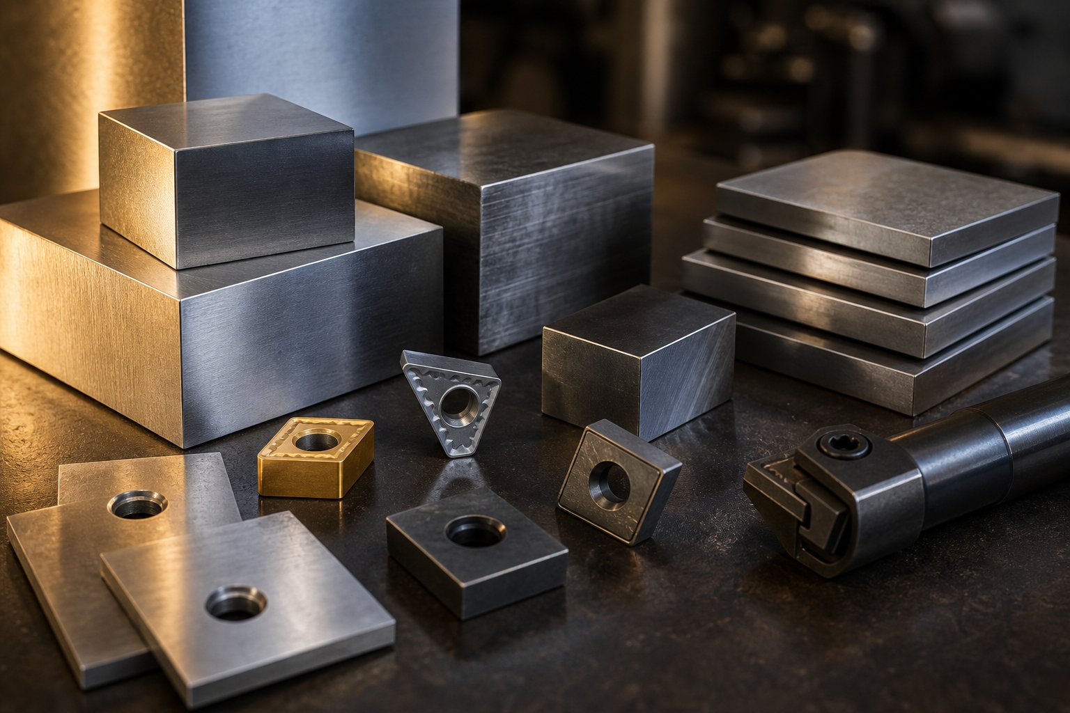
The geometry-material-volume alignment from Step 1 tells you what the die needs to do. Material selection determines how long it can keep doing it. Different die components face different stresses - cutting edges endure abrasive wear, forming surfaces resist galling, and structural plates absorb impact - so no single steel grade serves every role. Choosing the right metal stamping materials for each component is where die longevity is won or lost.
Choosing Between D2, A2, and S7 Tool Steels
Three tool steel grades dominate stamping die work, each optimized for a different failure mode:
D2 is the go-to for long-run blanking and piercing dies. Its high carbon (1.40-1.60%) and chromium (11.00-13.00%) content creates abundant hard carbides that resist abrasive wear exceptionally well. D2 reaches 54-61 HRC and handles stamped steel production runs well into the millions. The trade-off? It is less tough than other options and harder to machine and grind, so it is not the best pick for dies subjected to heavy shock loads.
When you need balanced performance - good wear resistance plus moderate toughness - A2 fits the gap. With less chromium (4.75-5.50%) and slightly less carbon than D2, A2 achieves 57-62 HRC while remaining more machinable. It suits coining dies, trimming dies, long punches, and large blanking dies where some impact resistance matters alongside edge retention. For medium-volume production under 1,000,000 parts, A2 often delivers the best cost-to-performance ratio.
S7 brings shock resistance that neither D2 nor A2 can match. Its lower carbon (0.45-0.55%) and reduced chromium (3.00-3.50%) give it excellent impact toughness at a working hardness of 48-58 HRC. Use S7 for heavy blanking, cold forming, bending dies, and any operation where the punch encounters sudden, high-energy loads. It wears faster than D2, but it will not chip or crack under conditions that would shatter a harder steel.
| Property | D2 | A2 | S7 |
|---|---|---|---|
| Hardness Range (HRC) | 54 – 61 | 57 – 62 | 48 – 58 |
| Toughness | Low to moderate | Moderate | High |
| Wear Resistance | Excellent | High | Moderate |
| Machinability | Difficult | Moderate | Good |
| Typical Die Applications | Long-run blanking, piercing, trim dies, stamping dies | Coining, trimming, large blanking, long punches | Heavy blanking, cold forming, bending dies, riveting |
The workpiece material matters here too. Stainless steel stamping and high-strength grades exert loads that can approach the hardness of the die itself, pushing you toward D2 or powder metallurgy steels. Aluminum stamping, by contrast, generates less wear but higher galling risk, making surface treatments more important than raw hardness.
When Carbide Inserts and Coatings Pay Off
Solid tool steel handles most production volumes, but carbide inserts extend die life by 500-1000% in specific situations - particularly fine blanking, shallow drawing, and high-volume piercing of abrasive materials. Their extreme hardness makes them ideal for stainless steel metal stamping where abrasive wear dominates. The catch is brittleness: carbide cracks under heavy impact, so reserve it for low-shock, high-wear stations rather than forming operations.
Coatings offer a middle path. Rather than replacing the entire insert material, you add a hard, low-friction surface layer that combats galling and extends sharpening intervals. Common options include:
- TiN (Titanium Nitride) - general-purpose coating that reduces friction and adds surface hardness; good for moderate-volume stamping across most materials.
- TiCN (Titanium Carbonitride) - harder than TiN with better wear resistance; suited for higher-volume or abrasive-material applications.
- TiAlN (Titanium Aluminum Nitride) - excellent heat resistance and wear performance; effective for aluminum metal stamping and high-speed operations where galling is the primary failure mode.
- CrN (Chromium Nitride) - good adhesion resistance; works well when forming galvanized steels where zinc buildup is a concern.
PVD (Physical Vapor Deposition) application is generally preferred because it operates at lower temperatures, avoiding distortion and the need to re-harden the substrate. One industry comparison showed a PVD-coated, ion-nitrided tool producing over 1.2 million parts versus just 50,000 for a chrome-plated tool of the same base steel. That is the kind of ROI that justifies coating costs on high-volume stamped aluminum or stainless parts.
Selecting Die Set and Holder Materials
Not every component needs premium tool steel. Die shoes, punch holders, and retainer plates serve structural roles - they maintain alignment and distribute load rather than cutting or forming material. Overspecifying these parts inflates cost without improving die life.
Common choices for die set components:
- Cast iron (ductile grades like D4512 or D6510) - excellent vibration damping, cost-effective for large die shoes, good machinability. Suited for dies running moderate volumes with standard press loads.
- Pre-hardened steel (AISI 4140 or equivalent at 28-34 HRC) - higher stiffness and load capacity than cast iron. Use for progressive die shoes and heavy-tonnage applications where deflection control matters.
- Medium-carbon steel (AISI 1045, heat treated to 30-35 HRC) - standard choice for retainer plates that secure punches and die inserts.
The guiding principle: spend your premium material budget on the components that contact the workpiece - punches, die blocks, and forming inserts. Support everything else with appropriately specified structural steel or iron that delivers stiffness without unnecessary cost.
With materials selected for every component, the next challenge is translating your die design into precise engineering calculations - clearances, cutting forces, and strip layout - that ensure the die performs exactly as intended under real press loads.
Step 3 Engineer the Die Design and Calculate Forces
Materials give the die its physical backbone, but engineering gives it precision. This phase turns your part analysis and material choices into hard numbers - clearances measured in hundredths of a millimeter, tonnage requirements calculated to the ton, and strip layouts sequenced station by station. Get the stamping die design math right here and machining becomes straightforward execution. Get it wrong and you will discover the errors during tryout, after burning through expensive tool steel and machine time.
Calculating Die Clearance for Your Material and Thickness
Die clearance is the gap between the punch cutting edge and the die opening edge. It controls how the material fractures during shearing: proper clearance aligns the fracture planes from top and bottom of the sheet so they meet cleanly, producing a smooth cut edge with minimal burr. Too tight, and the punch works harder, wears faster, and may fracture. Too loose, and you get excessive burrs, rollover, and poor edge quality.
Die clearance per side = Material thickness × Clearance percentage. For most mild steels, use 5-10% per side. Softer materials like aluminum use 5-7%, while harder materials like stainless steel require 10-12% or more.
Imagine you are blanking a 1.5 mm thick mild steel part. At 8% per side, your clearance is 1.5 mm × 0.08 = 0.12 mm on each side of the punch. That means the die opening is 0.24 mm larger than the punch in total diameter. For a stainless steel part of the same thickness, you might increase to 10-12% per side - yielding 0.15 to 0.18 mm per side - because the harder material generates higher lateral forces during shearing.
A few practical realities affect these calculations in your sheet metal stamping design. Thinner stock (under 0.5 mm) demands tighter absolute tolerances on clearance, since even 0.01 mm variation shows up as edge defects. Thicker stock (above 3.0 mm) benefits from clearances pushed toward the higher end of the range to reduce punch loading. And as MISUMI's engineering guidance notes, modern practice suggests that 11-20% clearance values can considerably reduce tooling strain and extend operational life for certain applications, particularly when edge finish requirements are less critical than die longevity.
Determining Press Tonnage Through Force Calculations
Every stamping project needs a press with enough force to shear the material cleanly without straining the machine. Undersized press capacity causes stalling, tool damage, and inconsistent parts. Oversized capacity wastes capital. The calculation for press stamping force in blanking and piercing operations is straightforward:
Cutting Force (tons) = Perimeter of cut (in) × Material thickness (in) × Shear strength (tons/in²)
For example, blanking a rectangular part measuring 3 inches by 2 inches from 0.060-inch mild steel (shear strength approximately 25 tons/in²) looks like this: Perimeter = 2(3 + 2) = 10 inches. Force = 10 × 0.060 × 25 = 15 tons. Simple enough for a single station.
Real-world die stamping operations add complexity. A progressive die performs multiple cuts per stroke - every piercing punch, every blanking station, every notch contributes force simultaneously. You must sum the tonnage across all active stations in a single stroke. Then add the force from stripper springs, nitrogen cylinders, and any forming or bending operations. Industry standard practice applies a 15-20% safety factor on top of the calculated total to account for material variation, tool wear, and friction.
The shear strength values driving these calculations vary significantly by material:
| Material | Approximate Shear Strength (tons/in²) | Relative Force Demand |
|---|---|---|
| Aluminum (soft) | ~11 | Low |
| Brass (half-hard) | ~20 | Moderate |
| Mild steel (CR/HR) | 25 – 27 | Moderate-High |
| Stainless steel (annealed) | ~37 | High |
| Stainless steel (half-hard) | ~50 | Very High |
Notice how half-hard stainless demands nearly five times the force of soft aluminum for identical geometry. This is exactly why material selection in Step 1 cascades directly into press capacity and metal stamping die design decisions here.
Progressive Die Strip Layout and Station Sequencing
For high-volume stamping design, the strip layout is where engineering creativity meets production economics. A progressive die strip layout defines how the part develops station by station as the coil feeds through the die. Good layouts maximize material utilization (targeting above 75%), maintain strip rigidity during feeding, and sequence operations to avoid interference between stations.
The strip layout also determines whether your design functions as a compact progressive system or requires transfer stamping - where individual blanks are mechanically moved between separate die stations. Transfer setups suit larger parts that exceed practical strip-width limits but add mechanical complexity.
Here is the sequential process for creating an effective strip layout:
- Orient the part on the strip - test multiple angles and nesting arrangements to find the orientation that minimizes strip width and scrap. Angular nesting can improve material utilization significantly for irregular shapes.
- Determine feed progression (pitch) - calculate the distance the strip advances per stroke. This equals the part length in the feed direction plus the bridge width (typically 1.25 to 1.5 times material thickness) needed between parts for strip integrity.
- Sequence operations by station - place piercing and notching in early stations, forming and bending in middle stations, and final blanking or cutoff at the last station. Each station should perform work that does not distort features created upstream.
- Place pilot holes in the first or second station - these holes engage pilot pins at every subsequent station, correcting for minor feed inaccuracy and ensuring feature-to-feature precision across all operations.
- Design the carrier strip - the material connecting each part-in-progress must be strong enough to push through all stations without buckling, yet positioned so it does not interfere with forming operations. Stretch web carriers allow vertical part movement during drawing.
- Verify idle stations where needed - insert empty stations between heavy operations to reduce peak tonnage per stroke and provide physical space for complex tooling.
- Calculate total strip width and confirm coil availability - strip width equals part width plus two edge margins. Verify that standard coil stock is available in the required width and thickness.
CAE simulation software can validate the entire stamping design before any steel is cut. Modern FEA tools simulate material flow, predict thinning and springback, and flag interference issues station by station. This virtual validation replaces much of the costly physical trial-and-error that historically plagued progressive die development - a significant advantage when your die budget runs into five or six figures.
With clearances calculated, tonnage confirmed, and strip layout finalized on screen, the engineering phase is complete. The numbers now need to become physical steel - and that means moving into the machining phase where tolerances in the thousandths become reality.
Step 4 Machine Die Components to Specification
Engineering drawings define the die on paper. Machining makes it real. This phase transforms hardened tool steel blanks into precision components where tolerances measured in microns separate a die that runs millions of cycles from one that fails in thousands. Whether your shop relies on manual surface grinders or a full CNC cell, the machining sequence follows the same logic: remove bulk material first, refine geometry progressively, and finish working surfaces last.
Every tool and die maker recognizes this workflow as the heart of metal stamping tooling production. Here is the sequence from roughing to final finish:
- Rough machine die blocks and punch blanks - remove bulk material, leaving 0.5-1.0 mm stock on all critical surfaces for finish operations.
- Stress relieve - thermally relax internal stresses introduced during rough cutting (covered in Step 5) to prevent distortion during final machining.
- Semi-finish machine - bring dimensions within 0.05-0.10 mm of final size using CNC milling or conventional milling with careful setups.
- Heat treat to target hardness - harden and temper components before final grinding (detailed in Step 5).
- Finish grind all datum surfaces - surface grind die faces and punch flats to establish parallelism and reference planes.
- Wire EDM or jig grind profiles - cut final punch and die contours to size with micron-level accuracy.
- Final polish and deburr - bring working surfaces to required Ra values and break all sharp non-cutting edges.
Rough Machining and CNC Milling Die Blocks
Rough machining sets the foundation. For shops with CNC capacity, three-axis milling centers handle the bulk removal efficiently - hogging out pockets, step-drilling relief areas, and profiling external contours with 0.5 mm or more left for finishing. Feed rates stay aggressive here because dimensional precision is not yet critical, but you need to watch for thermal distortion in large die blocks. Flood coolant and balanced cut depths prevent stress buildup that warps the part later.
Shops running manual equipment can accomplish the same work through conventional milling, drilling, and jig boring. Manual approaches take longer but remain viable for single-station and compound dies where geometry is straightforward. Jig boring, in particular, delivers positional accuracy within 0.01-0.02 mm for guide pin holes and dowel locations - adequate for standard die and fabricating work when CNC boring is unavailable.
Regardless of method, rough machining accuracy for milling typically falls in the IT11-IT13 tolerance range, with surface roughness around 5-20 micrometers Ra. That is nowhere near final spec, but it establishes the near-net shape that subsequent operations refine.
Wire EDM for Precision Die Profiles
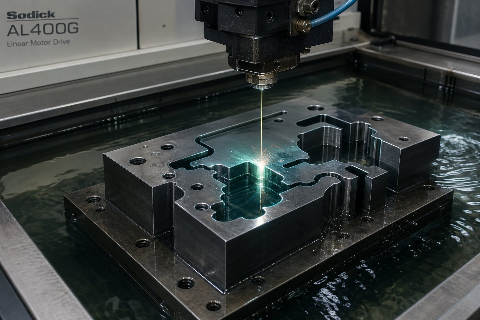
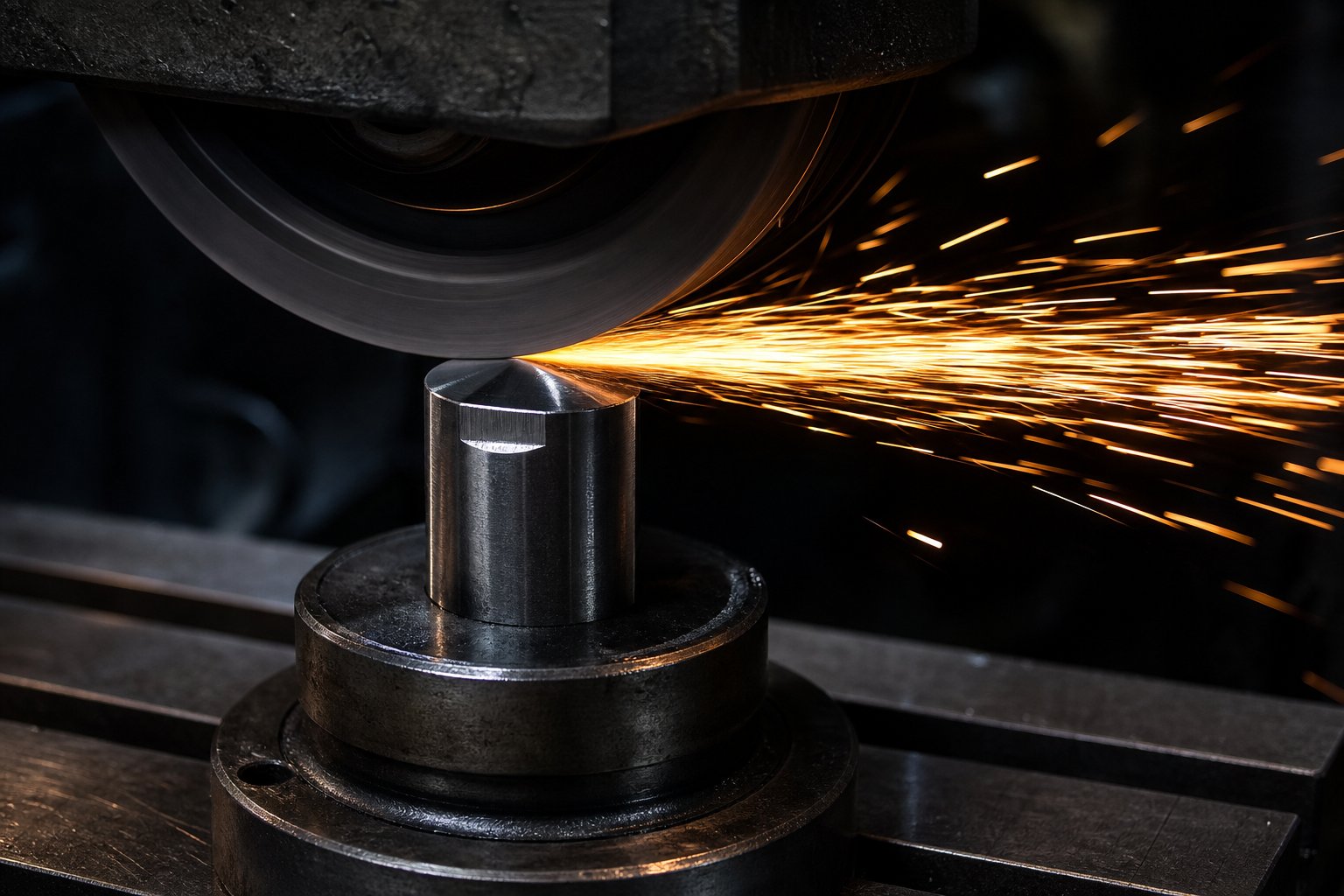
Complex punch and die contours - tight radii, intricate cutout shapes, sharp internal corners - often push beyond what conventional milling or grinding can achieve. Wire EDM solves this by using electrical discharges between a thin brass wire and the workpiece to erode material without mechanical contact. The wire never touches the steel, which means zero cutting force, no tool deflection, and the ability to machine fully hardened tool steel (60+ HRC) with the same ease as annealed stock.
For tool stamping applications, wire EDM delivers several critical advantages. It holds tolerances of ±0.002-0.01 mm depending on machine capability and setup. Internal corner radii are limited only by wire diameter (typically 0.1-0.3 mm) rather than cutter geometry. And because the process generates no mechanical stress, thin punches and delicate die sections maintain dimensional stability throughout cutting.
The typical wire EDM workflow for die profiles involves a rough pass followed by one or more skim passes. Each skim pass improves both dimensional accuracy and surface finish, with final passes achieving Ra values below 0.8 micrometers. For a metal stamping prototype where you are validating punch-to-die fit before committing to full production tooling, wire EDM allows rapid iteration - reprogram the path, recut the profile, and test again without scrapping the entire block.
Teams that lack in-house wire EDM or precision grinding capacity often partner with specialized manufacturers. Companies like YICHEN offer end-to-end die-making services covering the full machining workflow - from CAE simulation validation through CNC machining and surface finishing. Their custom stamping die solutions handle feasibility analysis, precision machining, trial runs, and inspection under one roof, which streamlines the process for sourcing managers and tooling engineers who need production-ready stamping tooling without building out an entire metal tool and die shop internally.
Surface Finish Standards and Their Impact on Part Quality
Surface finish on die working faces directly translates to stamped part quality. A rough die face scores the sheet metal on every stroke, creating cosmetic defects and accelerating material galling. A properly finished surface reduces friction, extends sharpening intervals, and produces parts that meet quality standards consistently.
Target surface roughness values for metal stamping tooling components:
| Die Component | Target Surface Finish (Ra) | Why It Matters |
|---|---|---|
| Punch cutting face | 0.2 - 0.4 micrometers | Prevents slug adhesion and reduces stripping force |
| Die opening (cutting land) | 0.2 - 0.8 micrometers | Controls burr formation and slug ejection quality |
| Forming surfaces (bending, drawing) | 0.1 - 0.4 micrometers | Minimizes material galling and scratching on finished parts |
| Guide pin and bushing bores | 0.4 - 0.8 micrometers | Ensures smooth die travel and prevents stick-slip wear |
| Stripper plate face | 0.8 - 1.6 micrometers | Adequate for material contact without excessive polishing cost |
Achieving these values requires grinding as the final operation on flat surfaces and polishing or lapping on contoured areas. Precision surface grinding reaches IT5-IT8 accuracy with Ra values of 0.16-1.25 micrometers - well within stamping die requirements for parallelism and flatness on die faces.
Beyond roughness numbers, two geometric tolerances determine whether the die functions correctly under press load. Parallelism between upper and lower die faces must hold within 0.01 mm across the full die width to prevent uneven clearance and tapered cuts. Perpendicularity of guide pin bores relative to the die shoe face keeps the upper and lower halves tracking straight - any angular error compounds through the full stroke length, magnifying misalignment at shut height.
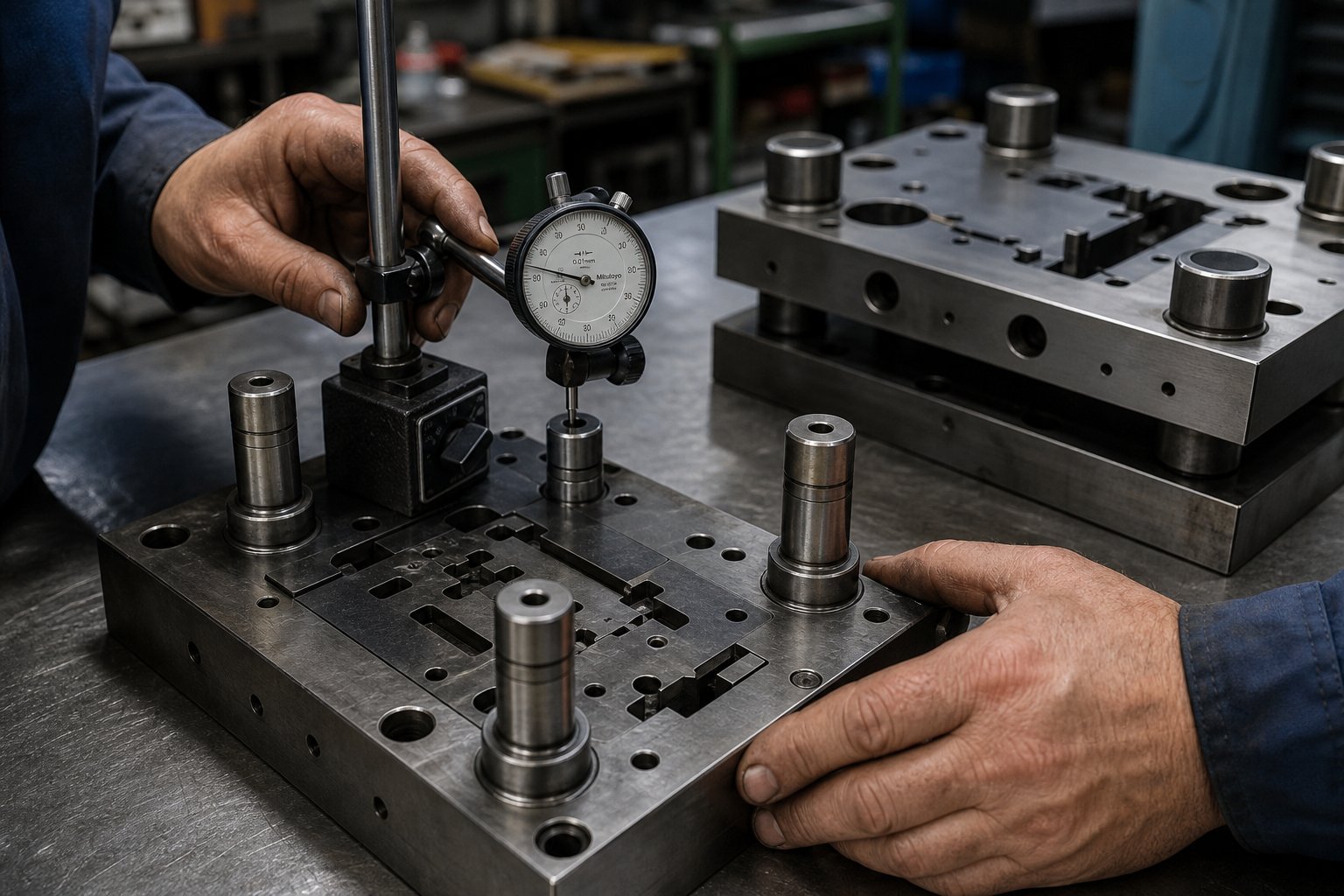
Verifying these tolerances requires dial indicator sweeps across ground surfaces and test-bar measurements in guide pin bores. Shops without CMM access can achieve reliable results using precision gauge blocks, dial indicators on magnetic bases, and careful technique. The key is measuring after heat treatment and final grinding - never assuming that pre-hardening dimensions survived the thermal cycle unchanged.
With all components machined, measured, and verified against print, they are ready for the thermal processing that transforms raw tool steel into hardened, wear-resistant die surfaces capable of surviving production volumes.
Step 5 Heat Treat Die Steels for Maximum Service Life
Precision machining gives the die its geometry. Heat treatment gives it durability. Two punches can share identical dimensions and the same tool steel grade, yet behave completely differently under press load - one lasting millions of hits, the other chipping within weeks. The difference is microstructure, and microstructure is shaped entirely by the thermal cycle applied to the steel. For steel stamping dies expected to survive high-volume production, heat treatment is not a checkbox step. It is the single process that determines whether your stamping tool and die investment pays off or fails prematurely.
Heat treatment quality directly determines die service life. A 50°F deviation in austenitizing temperature or a missed tempering cycle can shorten tool life dramatically, regardless of how precisely the die was machined.
The complete heat treatment sequence for sheet metal stamping dies follows a specific order, and skipping or rushing any stage invites failure:
- Stress relieve after rough machining to release residual stresses before hardening.
- Preheat gradually to reduce thermal shock risk.
- Austenitize at the correct temperature to dissolve carbides and form austenite uniformly.
- Quench using the appropriate medium (air, gas, oil, or salt bath) based on steel grade and section size.
- Cryogenic treat (optional) to convert retained austenite for dimensional stability.
- Temper - double or triple - to relieve quench stresses and develop the optimal hardness-toughness balance.
- Final grind after the thermal cycle is complete.
Hardening and Quenching Die Steels Correctly
Hardening transforms the steel's crystal structure from relatively soft phases into martensite - the hard, wear-resistant structure that lets stamping die components cut and form sheet metal millions of times. The process starts with preheating, moves through austenitizing, and finishes with quenching.
Preheating reduces the temperature gradient between the die's surface and core. Tool steels have low thermal conductivity, so heating too quickly creates internal stress that causes cracking or distortion. For D2, the standard preheat range is 1200–1250°F (649–677°C), held until the cross-section reaches uniform temperature. Heavy die blocks need longer equalization time than thin punches.
Austenitizing dissolves alloy carbides into the steel matrix and converts the structure to austenite. Each grade has its own critical temperature window:
- D2 - 1795–1875°F (980–1025°C), with 1850°F often used as a practical target.
- A2 - 1750–1800°F (954–982°C), slightly lower than D2 due to different alloy balance.
- S7 - 1700–1750°F (927–954°C), kept lower to preserve toughness.
Soaking time begins only after the entire section reaches target temperature - a common reference is 45–60 minutes per inch of thickness. Too low a temperature or too short a soak leaves carbides undissolved, reducing hardness and wear resistance. Too high or too long causes grain coarsening, excessive retained austenite, and increased cracking risk.
Quenching locks in the hard martensitic structure by cooling fast enough to suppress soft phase formation. D2 is an air-hardening steel, meaning controlled air cooling or gas pressure quenching achieves full hardness with minimal distortion - a major advantage for stamping steel components with complex geometry. A2 also air-hardens effectively. S7 may use oil quenching for heavier sections where air cooling alone does not achieve sufficient hardness throughout the core.
After quenching, the die component should cool to approximately 120–150°F (50–66°C) before tempering begins. At this stage the steel is extremely hard but dangerously brittle - fresh martensite under high internal stress. Delaying tempering overnight risks spontaneous cracking, especially in complex die geometries.
Tempering Cycles for Optimal Toughness and Hardness
Tempering reheats the quenched steel to a controlled temperature below the critical range, relieving internal stresses and converting brittle as-quenched martensite into a tougher, more stable structure. Without tempering, stamped sheet metal production would destroy the die within days - the edges would chip, crack, or spall under cyclic press loads.
Double tempering is standard practice for cold-work die steels. The first cycle relieves the bulk of quench stress and begins stabilizing the microstructure. Cooling back to room temperature between cycles allows any retained austenite to transform into fresh martensite, which the second temper then stabilizes. For critical steel sheet stamping dies or gauges demanding dimensional stability, triple tempering provides additional insurance.
The tempering temperature determines final hardness and toughness balance:
| Tempering Strategy | Typical Temperature | Expected Hardness | Best Suited For |
|---|---|---|---|
| Low-temperature temper | ~400°F (205°C) | 60–62 HRC | Maximum wear resistance; low-impact applications |
| High-temperature double temper | 900–960°F (480–515°C) | 58–60 HRC | Dimensional stability, stress relief, long-run production dies |
For most stamping die components running production volumes, high-temperature double tempering at 900–960°F yields the safer balance. You sacrifice 1-2 HRC versus a low-temperature temper, but gain significantly better dimensional stability and cracking resistance - properties that matter far more when the die faces millions of hits over its service life.
Here is the practical takeaway: an under-hardened die (tempered too aggressively or austenitized too low) wears prematurely because the cutting edges lack sufficient hardness to resist abrasion from the workpiece. An over-hardened die (undertampered or tempered too cold) chips and cracks because it cannot absorb the impact energy of each press stroke. The goal is the narrow window in between - hard enough to resist wear, tough enough to absorb shock - and proper tempering is how you land there consistently.
Stress Relieving to Prevent Dimensional Distortion
Stress relieving is the often-overlooked step that prevents expensive rework. Rough machining introduces residual stresses into the die block from cutting forces, heat generation, and uneven material removal. If you harden the block without relieving these stresses first, they release uncontrollably during the austenitizing-quench cycle, warping the die beyond tolerance. The result is a component that no longer fits, requiring re-machining or scrapping - after you have already invested in the full heat treatment cycle.
The stress relief process heats the rough-machined component to a subcritical temperature (typically 1050–1200°F / 565–650°C for most tool steels), holds it long enough for the stress to relax uniformly, then cools slowly in the furnace. No quenching, no phase transformation - just controlled thermal relaxation. The part comes out dimensionally stable and ready for hardening with predictable, minimal distortion.
When to stress relieve:
- After heavy rough machining (especially asymmetric material removal from large blocks).
- After welding repairs on die components.
- Before final heat treatment of large or geometrically complex stamping die components.
- After aggressive grinding on hardened surfaces - a low-temperature stress relief at 25-50°F below the final tempering temperature prevents grinding cracks from propagating.
Cryogenic treatment represents the opposite end of the temperature spectrum. By cooling hardened steel to approximately -196°C (-321°F), retained austenite - a soft, unstable phase trapped during quenching - converts to martensite. This improves dimensional stability over time (no slow transformation causing size changes in service) and can enhance wear resistance. Cryogenic treatment is most relevant for precision dies, punches, gauges, and slitting tools where dimensional drift is unacceptable. For general-purpose sheet metal stamping dies, proper double tempering often delivers sufficient stability without the added cost and complexity of cryogenic processing.
The thermal cycle is complete when the die component emerges tempered, stable, and at its target hardness - ready for the final grinding pass that brings all surfaces to specification. Any grinding after heat treatment must use light passes, proper coolant, and controlled stock removal to avoid reheat damage that undoes the careful metallurgy you just invested in.
Step 6 Assemble and Align All Die Components
Your die components are now hardened, tempered, and ground to final dimensions. Each one is a precision part in isolation. Assembly is where those individual parts become a functioning system - and where careless work can undo every hour of machining and heat treatment that preceded it. A misaligned guide pin, incorrect shut height, or under-preloaded spring does not just produce bad parts. It damages the die itself, sometimes beyond economical repair. Proper assembly of metal stamping dies follows a deliberate sequence that verifies fit and alignment at every stage before the press ever cycles.
Fitting Guide Pins and Verifying Parallelism
Guide pins are the alignment backbone of any die stamp. They keep the upper and lower halves tracking in perfect registration through every stroke, absorbing the lateral forces that would otherwise shove the punch off-center relative to the die opening. Getting their fit right is non-negotiable.
The standard configuration uses a press fit (interference fit) in one shoe - typically the lower - and a slip fit through hardened bushings in the opposing shoe. The press fit locks the pin permanently in position with zero movement. The bushings provide guided travel with just enough clearance (usually 0.005-0.012 mm) for smooth cycling without lateral play. Lightly lubricate the bushings with die-specific oil during installation to prevent galling on first strokes.
Before mounting any other metal stamping components, verify guide pin perpendicularity. Place a dial indicator on a magnetic base against the pin shaft and sweep its full length. Acceptable runout is 0.01 mm or less over the working length. Any angular error here multiplies through the stroke - a pin that leans 0.02 mm at the shoe surface translates into 0.04-0.06 mm of misalignment at full stroke extension, enough to damage cutting edges or produce uneven shear.
With pins installed and checked, slide the upper shoe onto the guides. It should travel smoothly with zero perceptible side play. If binding occurs, check for burrs on the bushing bore or a slight misalignment between guide pin centers that forces the shoes out of parallel. Never force the upper shoe down - binding means something is wrong, and pressing through it damages both bushing and pin.
Parallelism between the upper and lower shoe faces completes the alignment check. Place a precision ground parallel bar across the lower shoe and sweep a dial indicator across the upper shoe face at closed position. Deviation should hold within 0.0005 inch per inch of die width. Correct any deviation with light lapping of the shoe face or by adjusting shim placement before proceeding.
Setting Die Shut Height and Spring Preload
Die shut height is the overall height of the assembled die in its fully closed position. This dimension must fall within the press's available die-height space - the distance from the ram face to the bolster top at bottom dead center, minus bolster thickness. Sounds straightforward, but confusion between press shut height and die shut height causes real damage. If the die is too tall for the press adjustment range, the frame stretches and connections compress under excessive force. If it is too short, the die never fully closes and parts come out incomplete.
Measure shut height with the die fully closed using a soft spacer (shim stock at material thickness) between punch and die faces. The total stack height - including any risers or parallels placed under the die shoe - is your die shut height. Confirm this value falls between the press's minimum and maximum die-height specification before bolting anything down.
Spring preload comes next. Whether you are using coil springs, urethane pads, or nitrogen gas cylinders, the rule is the same: springs should compress only 15-25% of their free length at full stroke. Exceeding this range causes fatigue failure - springs crack, gas cylinders lose pressure, and urethane pads take a permanent set. Measure the free length of each spring, calculate the compressed length at shut height, and verify the compression ratio falls within safe limits. If a spring compresses beyond 25% at shut, either the spring is too short or your shut height needs adjustment.
For die stamps running progressive operations, uneven spring preload across the stripper plate causes tilting during strip feeding, leading to misfeed and pilot damage. Check that all spring pockets are at equal depth and that springs are the same specification - mixing spring rates from different suppliers is a common but avoidable error.
Assembly Sequence from Shoe to Stripper Plate
Die assembly follows a bottom-up, outside-in logic. You establish alignment first (guide system), then mount working components (die block, punches), and finally install secondary systems (stripper, springs, pilots). Rushing through these steps or jumping the sequence introduces errors that compound through the die's working life.
Here is the complete assembly sequence for stamping dies:
- Clean all components - degrease surfaces, remove packaging oils, and inspect every part under good lighting for cracks, burrs, or shipping damage.
- Mount guide pins in the lower shoe - press fit into reamed bores, verify perpendicularity with indicator.
- Secure the die block to the lower shoe - tighten shoulder bolts in a cross pattern to prevent warping. Verify the die face is parallel to the shoe within spec.
- Install guide bushings in the upper shoe - confirm smooth sliding fit on the guide pins.
- Mount the punch holder and punches to the upper shoe - verify each punch aligns concentrically with its mating die opening by slowly closing the die and checking clearance uniformity.
- Install the backing plate - position between punch heads and the upper shoe to distribute impact force and prevent punch impressions in the softer shoe material.
- Fit the stripper plate with springs - set spring preload within the 15-25% compression range; confirm uniform strip pressure across the plate face.
- Install pilots, locators, and feed components - for progressive dies, ensure pilots engage strip material accurately at designed feed pitch.
- Verify all clearances with shim stock - slide material-thickness shim between each punch and die opening to confirm slight uniform drag with no binding.
- Perform a slow manual cycle (dry run) - inch the die closed without material, listening for contact, scraping, or binding at any point in the stroke.
For progressive metal stamping dies, this is also where you install bypass notches - small relief cuts in the die that allow the strip to feed forward even when a pilot pin is still partially engaged. Negative and positive bypass notches in sheet metal stamping dies serve the same core function but differ in geometry. Negative bypass features a relieved entry angle that pushes the strip laterally as it advances, while positive bypass provides a raised guide surface. Both types prevent strip buckling and pilot breakage during feed progression, particularly at higher press speeds where feed timing becomes critical.
Even with careful sequencing, certain assembly errors persist in shops that rely on experience over measurement. Here are the most common failures and what they cause:
- Misaligned guide pins - causes galling between bushings and pins, increasing friction until the die binds mid-stroke. Progressive damage destroys both bushing and pin surfaces.
- Incorrect shut height (die too tall for press) - generates excessive tonnage that overloads the press frame, breaks punches, and can crack the die shoe.
- Insufficient stripper spring pressure - allows the sheet metal to cling to the punch on the return stroke, pulling slugs back through the die and jamming subsequent strokes.
- Uneven bolt torque on die block mounting - introduces a tilt in the die face that creates non-uniform clearance, producing tapered shear on one side and excessive burr on the other.
- Missing or misplaced backing plate - allows punch heads to mushroom into the softer shoe steel, gradually losing concentricity and increasing clearance beyond tolerance.
Each of these errors is detectable before the first production hit - if you measure. The 30 minutes spent sweeping indicators and checking shim drag saves days of troubleshooting and weeks of waiting for replacement components.
A fully assembled die sitting on the bench is not yet a production tool. It becomes one only after running real material through it, measuring the output, and correcting the inevitable discrepancies between design intent and physical reality. That validation process - die tryout - is where the assembly either proves itself or reveals what needs adjusting.
Step 7 Run Die Tryout and Adjust for Production Quality
A fully assembled die sitting in the press is still unproven. Until real material feeds through it and the output passes inspection, the tooling is a hypothesis - not a production tool. Die tryout is the process of testing that hypothesis methodically, starting with low-risk hits and escalating toward full production conditions while diagnosing and correcting every deficiency along the way. Rushing this phase to meet a deadline is how shops end up shipping bad stamped metal parts or destroying tooling on the third production run.
Tryout is iterative by nature. Plan for multiple cycles of hit, measure, adjust, and re-hit. Shops that treat tryout as a single pass consistently face production failures, emergency die repairs, and quality escapes that cost far more than the extra day of careful validation.
Running First Hits from Paper to Production Material
The progressive approach to first hits minimizes risk to the die while revealing problems early. Think of it as a controlled escalation:
- Paper hits - close the die on a sheet of paper or cardboard at reduced press speed. The impression reveals whether all punches contact uniformly, whether the shut height is correct, and whether any component interferes before it should. No metal, no risk of tooling damage.
- Soft material hits (aluminum or copper) - run a few strokes on soft, thin sheet stock. Aluminum deforms easily, so it exposes alignment issues, incomplete forming, and clearance problems without subjecting hardened punches to full cutting loads. Check the soft-material parts for shear pattern and symmetry.
- Production material at slow speed - feed actual production-grade sheet into the die stamping press at reduced speed (single-stroke mode). Inspect each metal stamped part immediately for burrs, dimensional accuracy, edge condition, and surface defects.
- Production speed with strip loaded - once slow-speed parts pass inspection, ramp up to target strokes per minute. Some problems - misfeed, slug pulling, heat buildup - only appear at production cadence.
As MetalForming Magazine notes, the first completed part from a fully threaded progressive die may not conform to dimensional requirements immediately. Stampers often must run several parts with the strip fully loaded before the die settles into producing good output, because initial strokes may leave the press ram offloaded in areas that require full strip tension to form correctly.
Identifying and Correcting Common Die Problems
Every tryout reveals something - the question is whether you can read what the parts are telling you. Each defect on a metal stamped part traces back to a specific root cause in the die, and each root cause has a targeted fix. Here are the most common tryout defects mapped to their origins and corrections:
| Defect | What You See | Root Cause | Corrective Action |
|---|---|---|---|
| Excessive burr | Raised sharp edge above 10% of material thickness | Insufficient punch-to-die clearance, or worn/dull cutting edges | Re-grind cutting edges; verify and adjust clearance per side; check alignment |
| Slug pulling | Slugs stuck to punch face, pulled back through the die | Inadequate die land length, insufficient vacuum break, or oil suction effect | Increase die land to 1.0-1.5x material thickness; add slug retention features; reduce lubrication on punch face |
| Uneven shear marks | Burnish band width varies around the cut perimeter | Punch-to-die misalignment; non-parallel die faces | Re-check guide pin alignment; re-grind die faces for parallelism; verify mounting bolt torque pattern |
| Springback | Bend angle opens beyond target after forming | Elastic recovery in material; insufficient overbend compensation in die geometry | Increase overbend angle (typically 2-5 degrees for mild steel, more for high-strength); add coining or bottoming at bend apex |
| Cracking at bends | Fractures on outer bend radius | Bend radius too tight for material ductility; grain direction parallel to bend line | Increase bend radius; rotate blank orientation; use more formable material grade |
| Misfeed / mislocated features | Holes or features shift position part-to-part | Pilot damage, feed-release timing error, or strip slippage | Inspect pilots for wear; adjust feed-release timing so rollers unclamp after pilot entry but before full engagement; verify progression distance |
Burrs deserve special attention because they are the most frequent tryout finding. According to industry defect analysis, burrs form when the punch and die fracture zones do not meet cleanly - either from incorrect clearance, worn cutting edges, poor alignment, or material thickness variation. If burr height exceeds 10% of stock thickness, the die needs intervention before production begins. Maintaining proper clearance and sharp edges is the primary control, and monitoring burr height during production provides early warning before parts drift out of specification.
Springback correction often requires the most iteration. High-strength materials and stainless steels bounce back aggressively, and the compensation angle is not always predictable from calculation alone. Expect two to three adjustment cycles - overbend slightly, measure, adjust, re-hit - before formed features hold the target angle consistently.
Achieving Consistent Part Quality Through Iteration
A single good part does not validate the die. Consistent quality across a sample run of 30-50 consecutive metal stamping parts confirms the tooling is stable. Measure critical dimensions on first-article parts using calipers, gauges, or CMM equipment against the part print tolerances. Track variation across the run - if hole position drifts by 0.05 mm over 30 hits, something is wearing or shifting, even if individual parts still pass inspection.
Key measurements during tryout validation:
- Burr height - verify below the maximum callout (often 0.05-0.10 mm for precision stamped metal parts).
- Feature-to-feature dimensions - confirm hole spacing, edge distances, and bend locations hold within print tolerance.
- Bend angles - measure with protractor or optical comparator after full elastic recovery.
- Flatness - check blanked parts on a surface plate with feeler gauges; coil set or residual stress can bow flat parts.
- Surface condition - inspect for scratches, galling marks, or die impressions that indicate tooling contact issues.
When all dimensions hold across the sample run, document the press settings - tonnage, shut height, feed length, speed, and lubrication setup. These become your baseline for production startup and future die setups on the same metal stamping machine. Any deviation from these settings during production is a troubleshooting starting point when quality drifts.
Tryout is also the moment to confirm press tonnage under actual load. Many shops perform a stop-block lead reading with the die fully threaded - checking whether the press gaps or deflects under the real forces generated by all active stations simultaneously. If the press deflects, the ram must come down slightly to maintain correct forming depth and cut quality, especially on thicker or high-strength stamped metal parts.
The stamped parts passing inspection consistently marks the transition from tooling development to production readiness. But production readiness is not the finish line - it is the starting point of ongoing maintenance responsibility that determines whether this die actually survives the millions of hits you designed it for.
Step 8 Maintain Your Die and Know When to Outsource
Consistent parts rolling off the press during tryout feel like a finish line. In reality, they mark the start of a much longer race. A metal stamping die built from premium tool steel and precision-machined to micron tolerances will still degrade stroke by stroke - cutting edges dull, guide pins wear, springs fatigue, and alignment drifts. The difference between a die that survives millions of hits and one that fails at 200,000 comes down to disciplined, schedule-driven maintenance performed before defects appear in production parts.
Establishing Sharpening Schedules and Inspection Intervals
Effective maintenance ties directly to hit counts rather than calendar dates alone. A die running 50,000 strokes per week wears faster than one cycling 5,000 - obvious, yet many shops still default to weekly inspections regardless of actual production intensity. The stamping manufacturing process rewards evidence-based scheduling: track your hit counter, log burr trends, and let the data tell you when service is due.
A practical starting point for a custom metal stamping die in medium-volume production is sharpening review every 50,000-150,000 hits, depending on material hardness and tool steel grade. Stainless steel and high-strength materials accelerate edge wear, shortening intervals. Softer materials like aluminum and brass extend them. Adjust from there based on what you observe during inspections.
Here is what to inspect at each maintenance interval:
- Cutting edge condition - check for rounding, chipping, micro-cracking, and burr height on sample parts pulled just before shutdown.
- Guide pin and bushing wear - feel for looseness, listen for abnormal noise during cycling, and look for scoring or galling marks on pin surfaces.
- Spring fatigue - measure free length against original spec; replace any spring that has lost more than 10% of its free length or shows visible cracking.
- Alignment drift - sweep a dial indicator across upper and lower die faces at closed position; deviation beyond 0.01 mm indicates mounting shift or guide wear.
- Fastener security - check all mounting bolts, dowel pins, and retainers for looseness caused by cyclic vibration.
- Scrap evacuation paths - clear slug buildup, slivers, and debris that accumulate in die cavities and chutes between runs.
- Lubrication delivery - confirm that lubricant reaches all planned application points without blockage or dry spots.
Proper sharpening technique matters as much as timing. Surface grind the punch face and die land equally to maintain the original geometry and clearance relationship. Remove only enough material to restore a clean cutting edge - typically 0.05-0.10 mm per sharpening cycle. After grinding, adjust the shut height by the same amount removed to maintain correct die closure. Skipping that adjustment opens up clearance progressively with each sharpening, eventually producing the same burr problems you were trying to eliminate.
As MetalForming Magazine emphasizes, shops should track maintenance costs separately from repair costs. Preventive maintenance preserves the die's current condition. Repair restores something already broken. When the two get lumped together, management sees inflated "maintenance" costs and pressures the team to reduce scheduled service - exactly the wrong response. An increase in planned maintenance activity should correspond to a decrease in emergency repairs and hidden downtime costs.
Recognizing When a Die Needs Rework or Replacement
Sharpening and component swaps handle normal wear. But when the same station keeps failing shortly after service, or dimensional drift returns within a few thousand hits of a verified setup, routine maintenance has reached its limit. These patterns signal deeper issues - accumulated clearance change across the entire die, structural fatigue in the shoe, or a fundamental design shortcoming that no amount of grinding will fix.
Watch for these escalation triggers in the metal stamping manufacturing process:
- Recurring burr or dimensional drift even after verified sharpening and alignment correction.
- Chipping or cracking of cutting edges rather than gradual rounding - this indicates overload or material fatigue beyond what sharpening addresses.
- Guide pin or bushing replacement needed more than twice per year on a production die.
- Cumulative sharpening has removed enough material (typically 3-5 mm total) that shut height adjustment range is exhausted.
- Part tolerances have tightened due to engineering changes and the existing die geometry can no longer hold the new spec.
When these signs appear, the decision is between reconditioning (rebuilding worn sections and restoring alignment) and full replacement. Reconditioning suits dies where the shoe, guides, and overall structure remain sound but working components have exceeded their service life. Replacement is the right call when structural integrity is compromised, when cumulative rework costs approach new-build cost, or when production volume demands tooling capable of precision die stamping at automotive-grade consistency.
When to Partner with a Professional Die Maker
Many shops handle sharpening, spring replacement, and basic component swaps in-house effectively. That works for simple blanking dies and moderate production volumes. But there is a clear boundary where in-house capability runs out and professional metal stampers with full engineering resources become the better path.
| Scenario | In-House Maintenance Handles It | Professional Die Maker Required |
|---|---|---|
| Edge sharpening on standard tool steel | Yes - surface grinder and basic fixturing sufficient | No - unless geometry is complex or wire EDM reshaping needed |
| Spring and component replacement | Yes - stock replacement parts and standard assembly | No - unless custom components require re-engineering |
| Progressive die station rebuild | Possible if shop has wire EDM and CNC grinding | Yes - when multiple stations need redesign or CAE validation |
| Automotive stamping dies with PPAP requirements | Rarely - documentation and validation demands exceed most internal shops | Yes - full quality system, simulation, and inspection capability needed |
| New die for changed part geometry or higher volume | No - unless shop is a full-service toolroom | Yes - feasibility analysis, design, machining, and tryout all required |
| Die failure root-cause analysis requiring CAE simulation | No - most shops lack FEA software and simulation expertise | Yes - simulation identifies forming issues invisible to physical inspection |
A useful metal stamping dies company overview question to ask any potential partner: do they cover the full workflow from feasibility through production validation, or only discrete machining steps? The distinction matters because a die that fails repeatedly often needs the entire process revisited - not just a single component re-machined.
For teams that have outgrown their in-house die-making capacity or need production-grade tooling for high-volume contracts, partnering with a full-service provider eliminates the coordination overhead of managing separate vendors for design, machining, heat treatment, and tryout. YICHEN, for example, offers RFQ-ready custom stamping die solutions that span feasibility analysis, CAE simulation, precision machining, trial runs, and final inspection - the same workflow covered throughout this guide, executed under one quality system. That integrated approach is particularly valuable for automotive stamping dies and other precision applications where traceability and first-pass approval rates directly affect production timelines.
Whether you maintain your metal stamping die in-house or partner with a specialist, the principle stays the same: maintenance preserves the investment you made in every preceding step. Monitor hit counts, inspect systematically, sharpen before edges fail, and escalate honestly when routine care stops holding. A die built to survive millions of hits can only do so if the maintenance program behind it is equally disciplined.
Frequently Asked Questions About Making a Stamping Die
1. How long does it take to make a stamping die from scratch?
A simple single-station blanking die typically takes 4-8 weeks from design through tryout, while a complex progressive die can require 12-20 weeks or more. The timeline depends on part complexity, material selection, machining method (manual vs. CNC/wire EDM), heat treatment cycles, and the number of tryout iterations needed to achieve consistent part quality. Shops with in-house wire EDM and CNC capacity can compress timelines significantly compared to those outsourcing machining steps.
2. What is the best tool steel for stamping dies?
There is no single best tool steel - the right choice depends on the operation and production volume. D2 tool steel (54-61 HRC) excels in long-run blanking and piercing due to exceptional wear resistance. A2 offers a balanced combination of hardness and toughness for medium-volume dies and longer punches. S7 provides superior shock resistance for heavy blanking and bending operations. For extremely high-volume or abrasive-material applications, carbide inserts can extend die life by 500-1000% over solid tool steel in specific stations.
3. How do you calculate punch and die clearance for sheet metal stamping?
Die clearance per side equals material thickness multiplied by a clearance percentage. For mild steel, use 5-10% per side; softer materials like aluminum require 5-7%, while harder materials like stainless steel need 10-12% or more. For example, blanking 1.5 mm mild steel at 8% per side gives 0.12 mm clearance on each side, making the die opening 0.24 mm larger than the punch overall. Proper clearance ensures clean fracture alignment, minimal burr, and extended tool life.
4. What causes excessive burrs on stamped parts and how do you fix it?
Excessive burrs - raised sharp edges exceeding 10% of material thickness - result from insufficient punch-to-die clearance, dull or worn cutting edges, or misalignment between punch and die. The fix involves re-grinding cutting edges to restore sharpness, verifying and adjusting clearance per side to match material specifications, and checking guide pin alignment and die face parallelism. Monitoring burr height during production serves as an early warning system that triggers maintenance before parts drift out of specification.
5. When should you outsource stamping die making instead of building in-house?
Outsource when your project exceeds in-house equipment capability - particularly when you lack wire EDM for complex profiles, need CAE simulation for design validation, require automotive-grade PPAP documentation, or when progressive die stations need redesign. Full-service die makers like YICHEN handle feasibility analysis, simulation, precision machining, trial runs, and inspection under one quality system, eliminating multi-vendor coordination. This integrated approach is especially valuable for high-volume contracts where first-pass approval rates directly impact production timelines.


