


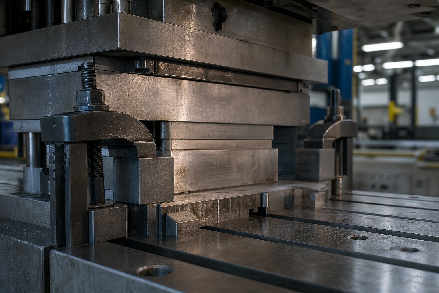
What Stamping Die Clamps Do and Why They Matter
Imagine your press running at 60 strokes per minute. The upper die slams into material, generates thousands of pounds of reverse load, and vibrations ripple through the bolster. What keeps both die halves locked in position through all of that? The answer is your clamping system, and if it fails, everything downstream fails with it.
Definition and Core Function of Stamping Die Clamps
Stamping die clamps are mechanical or power-actuated devices that secure the upper and lower halves of a press tool (die) to the ram (slide) and bolster plate, resisting all static and dynamic forces generated during the stamping cycle.
In a stamping press, the upper die half attaches to the slide while the lower half is clamped or bolted to the bed or bolster. The die clamp is the critical interface between these tooling components and the press structure itself. Its job goes beyond simply holding a heavy steel block in place. Each press stroke produces forming forces, snap-through shock, stripping forces, and vibration. A die clamp must resist all of these loads repeatedly, often millions of cycles over a production run, without allowing even fractional movement of the die shoe relative to the press.
Why Clamping Integrity Affects Part Quality and Press Safety
When you think about part quality issues, clamping rarely gets the blame. But it should. A die that shifts even a few thousandths of an inch mid-stroke introduces dimensional variation into every stamped part that follows. Punch-to-die clearances change. Pilots no longer align with pre-pierced holes. Progressive die stations lose registration. The result is scrap, tool damage, and unplanned downtime.
The safety dimension is equally serious. Die-setting fasteners are subject to cyclical loading from press vibrations and the retorquing that comes with repeated use. A single failed clamp under dynamic load can release a die section weighing hundreds or thousands of pounds. This is why redundant fastening, proper torque verification, and correct clamp selection are not optional best practices. They are fundamental safety requirements for every press setup.
This guide covers the full lifecycle of die clamps: types and operating principles, clamping force calculations, installation procedures, maintenance schedules, and a structured decision framework for selecting the right system. Whether you are a press technician setting dies daily, a tooling engineer specifying clamping for a new progressive die, or an operations manager evaluating quick die change upgrades, the sections ahead will give you the technical depth to make confident decisions.
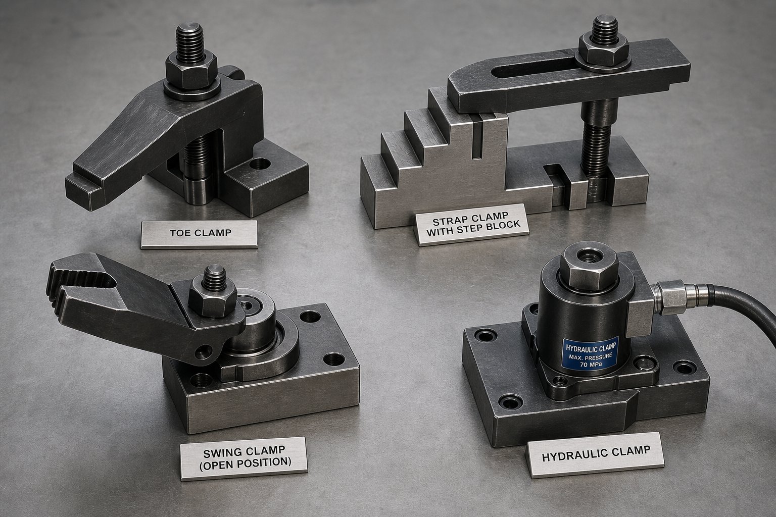
Complete Taxonomy of Die Clamp Types
Not all clamping devices do the same job the same way. A toe clamp holding a small compound die in a 60-ton OBI press has almost nothing in common with a magnetic platen securing progressive tooling in a 1,000-ton transfer press. Yet both fall under the umbrella of die clamping. To choose correctly, you need a clear picture of every category available, how each one retains the die, and where each fits best.
Manual Clamp Types and Their Configurations
Manual clamps rely on a human operator to position, tighten, and verify each fastening point. They are the most common and least expensive category, but they demand discipline in torque application and placement consistency.
Toe clamps grip the edge of a die shoe with a short, low-profile finger that hooks over the die flange. A T-slot bolt threads up through the bolster slot, and a nut draws the toe down against the die surface. They work well in tight spaces where overhead clearance is limited, and you will often see them on smaller OBI and gap-frame presses running low-tonnage jobs.
Strap clamps (sometimes called bar clamps or D clamps in shop shorthand) use a flat steel bar that bridges between the die shoe edge and a support point such as a step block. One end contacts the die, the other rests on the step block, and a T-bolt in the center pulls the bar down to generate clamping force through a lever-like mechanical advantage. Strap clamps are versatile and inexpensive, making them the default choice for job shops handling diverse die sizes.
Step block and clamp sets pair with strap clamps to bridge the height difference between the die shoe surface and the bolster. Step blocks come in graduated sizes, letting the operator match the support height to virtually any die shoe thickness. A well-matched step block and clamp set keeps the strap level, which distributes clamping force evenly. When the strap tilts because the step height is wrong, most of the load concentrates at the bolt rather than the die edge, dramatically reducing effective holding power.
Swing clamps pivot into position over the die flange and lock down with a T-bolt. Their main advantage is speed: the operator swings the clamp body out of the way during die loading, then rotates it back and tightens. This eliminates the need to fully remove and reinsert the clamp for each changeover. Swing clamps suit presses with frequent die changes where full hydraulic systems are not justified.
Slidable clamps move laterally along the T-slot to accommodate different die widths without repositioning the bolt. They reduce setup variability by keeping the clamp in a pre-indexed location that only needs a lateral slide adjustment. You will find these on presses running families of dies with similar but not identical footprints.
Power-Actuated Clamping Technologies
When you want to remove operator variability and compress changeover time, power-actuated systems take over. They apply consistent, repeatable force at the push of a button.
Hydraulic die clamps use pressurized fluid acting on a piston to generate clamping force. They have been used in metal forming for more than 50 years and remain heavily adopted because of their flexibility and reliability. Hydraulic clamps can be external (sliding into T-slots and gripping die edges), fixed-mount (bolted directly to the bolster or slide), or internal (integrated into the press bed). Internal configurations include swing clamps delivering 7 to 19 tons of force per unit, swing sink clamps providing up to 25 tons, and internal pull clamps that grip T-clamping bars attached to subplates. Safety features like zero-leakage directional control valves and pilot-operated check valves ensure the die stays clamped even during a power loss or hydraulic line failure.
Magnetic and Hydromechanical Systems
Magnetic clamping systems use electropermanent magnets embedded in custom plates bolted to the press bed and slide. Activating the system requires only about 0.5 to 3 seconds of electrical power to transition from unclamped to clamped. Once energized, the magnets hold the die without continuous power draw, maintaining full force even during a power outage. The concentrated magnetic field penetrates approximately 0.625 inches into the die base, providing uniform, distortion-free retention across the entire contact surface. Magnetic platens do not require die standardization the way hydraulic systems often do, though they demand flat, clean die surfaces made from magnetic-compatible steel for maximum holding force.
Hydromechanical clamps bridge the gap between fully manual and fully automated approaches. They use a T-bolt and clamping nut, much like a conventional setup, but integrate an internal piston that pressurizes when the operator applies the correct torque. A preload indicator pin extends to provide immediate visual confirmation that the bolt is properly loaded. The payoff is substantial: a 1-inch T-bolt hydromechanical clamp generates 22,000 pounds of clamping force with only 22 ft-lbs of torque. This gives stampers the feedback and consistency of a power system while retaining the simplicity of a manual workflow.
| Type | Actuation Method | Typical Tonnage Range | Die Change Speed | Relative Cost |
|---|---|---|---|---|
| Toe Clamp | Manual (T-bolt and nut) | Up to 200 tons | Slow (15-30 min per die) | Very Low |
| Strap / D Clamp | Manual (T-bolt, step block) | Up to 400 tons | Slow (15-30 min per die) | Low |
| Step Block and Clamp Set | Manual (paired with strap) | Up to 400 tons | Slow (15-30 min per die) | Low |
| Swing Clamp | Manual (pivot and T-bolt) | Up to 300 tons | Moderate (10-20 min) | Low-Medium |
| Slidable Clamp | Manual (lateral slide, T-bolt) | Up to 300 tons | Moderate (10-20 min) | Medium |
| Hydraulic Clamp | Hydraulic pressure (piston) | 50-2,000+ tons | Fast (1-5 min) | High |
| Magnetic Platen | Electropermanent magnet | 50-2,000+ tons | Very Fast (0.5-3 sec clamp time) | Very High |
| Hydromechanical Clamp | Manual torque + internal piston | Up to 600 tons | Moderate (5-15 min) | Medium |
Each category occupies a distinct position along the spectrum of cost, speed, and automation. But knowing what a clamp type is only gets you halfway. Understanding the mechanical principles behind each retention method, and recognizing how those principles break down under real operating conditions, is what separates reliable setups from the ones that shift mid-stroke.
How Each Clamping Technology Works at the Mechanical Level
A clamp either holds or it does not. But when one fails during a production run, diagnosing why requires more than visual inspection. It requires understanding the physics that generated the holding force in the first place. Each clamping technology relies on a fundamentally different mechanism, and each one degrades differently under real-world conditions. Knowing what happens inside the clamp gives you the ability to pinpoint die clamping force loss troubleshooting before a minor issue becomes a catastrophic die shift.
Friction and Mechanical Advantage in Manual Clamps
Every manual clamp, whether a strap clamp, toe clamp, or dimide clamp style device, retains the die through the same basic principle: a bolt under tension creates a normal force between the clamp face and the die shoe surface, and friction between those surfaces resists lateral movement. The mechanical advantage comes from the lever geometry. In a strap clamp, the bolt sits between the die edge and the step block. The closer the bolt is positioned to the die (rather than centered), the higher the proportion of clamping force transferred to the die surface.
- T-slot bolt providing axial tension
- Strap or toe body acting as a lever arm
- Step block providing the fulcrum reaction point
- Nut or fastener converting torque into linear preload
What causes force loss here? Oil or stamping lubricant on the die shoe surface reduces the friction coefficient, sometimes by 30 to 50 percent. Thermal cycling during long production runs causes bolt relaxation as the fastener expands and contracts. Vibration gradually loosens thread engagement. If you notice a manual clamp losing grip mid-run, check the contact surfaces for contamination first, then verify torque retention on the bolt.
Hydraulic Pressure Multiplication and Piston Design
Hydraulic die clamps exploit Pascal's law: pressure applied to a confined fluid transmits equally in all directions. A small-diameter pump piston pressurizes hydraulic fluid, which acts on a larger-diameter clamping piston. The area ratio between the two pistons multiplies the input force, generating tons of clamping load from a modest hydraulic supply.
- Hydraulic power unit generating system pressure (typically 3,000-5,000 PSI)
- Directional control valves routing fluid to clamp or release
- Clamping piston converting pressure into linear force
- Pilot-operated check valves locking pressure in if supply fails
- Pressure sensors monitoring real-time clamp status
The failure modes here are different from manual systems. Seal degradation allows internal leakage, gradually reducing the force the piston can sustain. Oil contamination with metal particles accelerates seal wear. Temperature extremes change fluid viscosity, affecting response time and peak pressure. A hydraulic clamp that holds perfectly at startup but drifts after four hours of production often points to a slow internal leak past a worn piston seal rather than an external problem.
Electromagnetic Field Clamping Principles
A magnetic die clamping system works on an entirely different physical basis. Electropermanent magnets combine two materials: aluminum-nickel-cobalt (AlNiCo), which magnetizes and demagnetizes easily, and neodymium, which holds its magnetic state with extreme tenacity. A brief electrical pulse aligns the AlNiCo poles to work with the neodymium, projecting a concentrated magnetic field several inches beyond the plate surface. A reverse pulse flips the AlNiCo poles to oppose the neodymium, collapsing the field back entirely within the plate itself.
- Neodymium magnets providing base field strength (high coercivity)
- AlNiCo elements acting as switchable flux gates (low coercivity)
- Magnetic plate housing with north-south pole grid pattern
- Electrical coil delivering short activation and deactivation pulses
- Proximity sensors verifying die contact (detecting gaps greater than 0.007 in.)
Current systems deliver up to 14 tons of holding force per square foot, but that number depends heavily on surface conditions. Any air gap, rust scale, stamping slug, or non-magnetic material between the plate and die reduces flux transfer and weakens the hold. Temperature also matters: standard magnetic platens handle up to 250 degrees Fahrenheit, with specialty units rated to 450 degrees at significantly higher cost. Unlike hydraulic systems, there is nothing to leak or wear mechanically. But a dirty bolster surface is the number one cause of reduced holding force in magnetic systems.
Hydromechanical clamp operation combines elements of both manual and hydraulic approaches. The operator manually torques a T-bolt, but the clamp body contains a sealed piston chamber. As torque reaches the target value, the internal piston pressurizes, locking the preload mechanically while extending a visual indicator pin. This self-contained hydraulic amplification means a 1-inch T-bolt produces 22,000 pounds of clamp force from just 22 ft-lbs of torque. No external hydraulic supply is needed. If that indicator pin retracts during a run, you have immediate proof that bolt preload has dropped, making force loss visible rather than hidden.
Each technology has a distinct environmental vulnerability: oil kills friction-based manual clamps, seal wear undermines hydraulic systems, and surface contamination degrades magnetic platens. Recognizing which failure mode applies to your system is the first step toward preventing it. The next practical question is how much total force your clamps need to generate in the first place, which depends on your press capacity, stroke speed, and the specific forces your die produces during forming.
Clamping Force Calculation and Sizing Rules
Knowing which clamp type to use is only half the problem. The other half is knowing how much total force your clamping system must deliver. Get this wrong and you either over-engineer (wasting money and setup time) or under-engineer (risking die shift, fastener fatigue, and damaged tooling). Surprisingly, most die clamping force calculation guidance simply does not exist in standard tooling references. Here is how to work through it systematically.
Clamping Force Rules of Thumb and Their Engineering Basis
The industry-accepted starting points for stamping press clamping force requirements come from two well-established rules of thumb, referenced by manufacturers like Pascal and reinforced in PMA technical literature:
- Crank presses: Total clamping force should equal at least 10% of rated machine tonnage.
- High-speed presses: Total clamping force should equal at least 20% of rated machine tonnage.
- Hydraulic presses: Clamping force must exceed the die opening force.
Why the difference? It comes down to dynamics. A crank press running at moderate speed generates reverse tonnage (snap-through shock) when the punch fractures through material. That shock produces downward slide accelerations that can approach 10 times the acceleration of gravity, effectively multiplying the apparent weight of the upper die many times over for a few milliseconds. The clamping system must resist this momentary separation force without allowing the die shoe to lift off the ram face.
High-speed presses compound the issue. Faster stroke rates mean more frequent shock events with less time for vibrations to dampen between cycles. Stripping forces also increase with speed because the material has less time to relax off the punches. The 20% rule accounts for this amplified dynamic environment. The 20% method generally overestimates actual requirements because it assumes maximum specified die weight and maximum strokes per minute. That built-in margin provides the redundancy that safety-critical fastening demands.
Step-by-Step Sizing Methodology for Your Application
Die clamp sizing follows a logical sequence. Walk through these steps for every new die setup or when evaluating whether your current configuration has adequate margin:
- Identify the press rated capacity and type. A 600-ton crank press gives you a baseline. A 600-ton high-speed press demands double the clamping percentage.
- Apply the appropriate rule of thumb. For the 600-ton crank press: 600 x 0.10 = 60 tons minimum total clamping force. For a 600-ton high-speed press: 600 x 0.20 = 120 tons minimum total.
- Split the force between upper and lower die. Divide your total evenly: 30 tons holding the upper die to the slide, and 30 tons securing the lower die to the bolster (for the crank press example).
- Account for bridge clamp geometry. When using strap clamps with step blocks, only about half the bolt tension acts on the die. The other half pushes into the fulcrum block. If you need 30 tons on the die, you must generate 60 tons total bolt preload across all strap clamps on that die half.
- Select the quantity and size of die bolts or clamps. Divide the required force per die half by the rated clamping force of each individual unit. For example, if each T-bolt assembly delivers 5 tons of effective force on the die, you need at least 6 clamps per side (30 / 5 = 6).
- Verify that clamp locations provide balanced loading. Distribute the clamps symmetrically around the die perimeter so no single edge carries a disproportionate share of the retention load.
Pascal's catalog notes an important principle here: it is better to use more clamps at lower individual force than fewer clamps at higher force. This distributes loading more evenly across the die shoe, reduces localized stress concentrations, and provides continued retention if one fastener fails.
When Standard Rules Do Not Apply
The 10% and 20% guidelines work well for straightforward blanking and forming operations. But certain applications generate forces that push well beyond those assumptions:
- Progressive dies with heavy material flow: Material pulling through multiple draw or form stations creates lateral forces that act on the die in directions the vertical clamps were not designed to resist. The heavier the draw reduction, the more lateral force transfers into the die shoes.
- Off-center loading: When the center of applied force does not align with the center of the die set (and therefore the center of clamping), a tilting moment develops. Clamps on one side of the die take a disproportionate share of the load. This is common in progressive dies where cutting, drawing, and forming do not produce symmetric resultant forces.
- Aggressive lifter forces: Nitrogen-spring or mechanical lifters pushing against the upper die during the return stroke add directly to the separation force. If a die uses 8 tons of lifter force and you only calculated 10 tons of upper die clamping, your effective safety margin has dropped to 20% instead of the planned 100%.
- High yield-to-tensile-strength materials: The ratio of yield strength to tensile strength directly affects reverse tonnage magnitude. Higher-strength steels and aluminum alloys with high YS/UTS ratios generate proportionally greater snap-through shock, demanding more clamping force than mild steel applications on the same press.
In these scenarios, treat the percentage rules as a floor, not a ceiling. Add lifter forces directly to your clamping requirement. For off-center loading, increase clamp density on the loaded side rather than relying on symmetric placement. And whenever your die bolts are doing double duty resisting both vertical separation and lateral shift, consider adding heel blocks or keys to carry the lateral component independently, so the bolts handle only the tensile separation load they were designed for.
Getting the force numbers right matters, but a perfectly calculated clamping force still fails if the installation is wrong. The torque applied to each bolt, the sequence in which they are tightened, and the hardware selection choices all determine whether your calculated force actually reaches the die shoe surface intact.
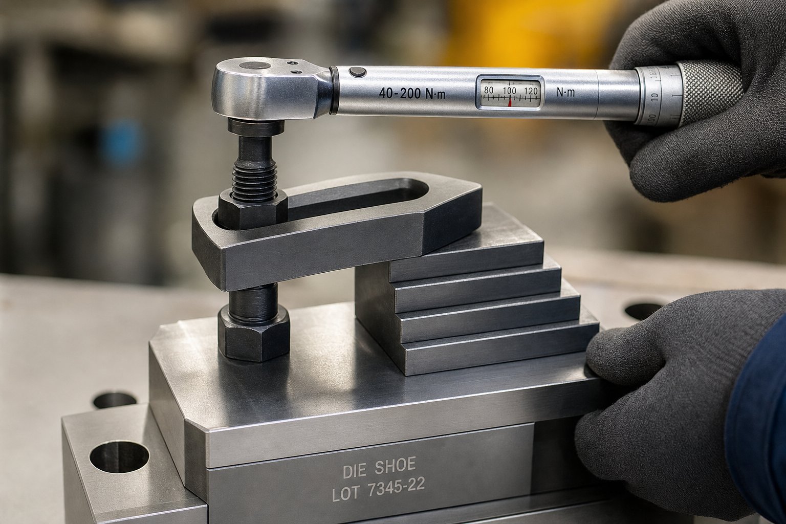
Installation Procedures and Torque Specifications
A well-chosen clamp system sized to the correct force still fails if the technician installing it uses the wrong bolt, skips a washer, or tightens in a random pattern. Installation is where calculations become reality, and it is where most clamping failures actually originate. The hardware, the sequence, and the verification steps after startup all determine whether the force you calculated on paper actually reaches the die shoe surface uniformly.
T-Slot Bolt Selection and Thread Engagement Requirements
Two fastener arrangements dominate stamping die installation. The first is the T-bolt and nut combination, where a bolt with a T-shaped head (typically 1-inch diameter) drops into the bolster or ram T-slot and a nut tightens down on top of the clamp. The second is the bolt and T-nut arrangement, where a T-nut sits inside the slot and a bolt threads down into it from above. The distinction matters because T-nuts must fit within the slot dimensions, which usually limits the threaded hole to 3/4-inch diameter. That smaller thread offers only about 60 percent of the tensile strength of a 1-inch bolt of the same grade. To achieve equivalent clamping force, you will need nearly twice as many clamps with the bolt-and-T-nut setup compared to 1-inch T-bolts.
Thread engagement length is critical. The minimum rule: the bolt must engage threads equal to at least one bolt diameter. For a 3/4-inch bolt threaded into a T-nut, that means at least 3/4 inch of thread engagement. The preferred engagement is 1.5 times the bolt diameter, or about 1-1/8 inches for that same fastener. A properly sized bolt requires no more than two washers to achieve this geometry, and the threads should not extend beyond the bottom of the T-nut.
Material grade matters just as much as diameter. At minimum, use SAE Grade 5 fasteners for any die clamping application. These are alloy steel, heat treated and tempered to established specifications. All U.S.-made Grade 5 bolts carry a manufacturer's mark on the head in addition to three radial lines indicating the grade. A bolt without a manufacturer's designation may be imported and could fail to meet mechanical strength requirements. Never use plain-carbon bolts or commercial threaded rod for die setting. Plain-carbon fasteners deliver roughly half the strength of Grade 5, and commercial threaded rod provides no traceable mechanical specification whatsoever.
Tightening Sequence and Torque Verification
Even with properly selected hardware, the order in which you tighten clamps directly affects how evenly the die seats against the bolster. A random tightening pattern concentrates clamping pressure on one side while leaving the opposite edge under-loaded. That imbalance allows the die to rock or shift under forming loads, creating part-to-part dimensional variation.
Follow this die clamp tightening sequence to achieve uniform pressure distribution:
- Position all clamps loosely around the die perimeter. Confirm that the die is centered on the bolster and resting flat.
- Snug the first clamp at the center of the longest die edge (or nearest the center of applied forming force) to just finger-tight contact.
- Move to the clamp directly opposite (across the die) and snug it to the same light contact.
- Proceed to the next pair of opposing clamps, working outward from center in a cross-pattern, similar to how you would torque a cylinder head or wheel lug.
- Once all clamps are snugged, return to the first clamp and apply 50 percent of final torque in the same cross-pattern sequence.
- Make a final pass at full target torque, again following the same sequence.
- Verify the final torque value on every clamp with a calibrated torque wrench.
Why the multi-pass approach? When a fastener is tightened, it stretches slightly within its elastic range, functioning like a tensioned spring. That stretch creates the clamping force holding the joint together. Fasteners for die setting perform best when tightened to approximately 75 percent of their yield stress. A multi-pass sequence lets adjacent fasteners settle together rather than the first bolt absorbing all the initial load and relaxing when the second bolt draws the die in a different direction.
Always use a torque wrench for the final pass. Over-tightening, which happens frequently when setup personnel add pipe extensions to ratchets or box wrenches, stresses the fastener beyond its yield point. This causes permanent elongation and a substantial loss of clamping strength. A bolt that has been permanently stretched should be discarded immediately and never reused.
Common Installation Errors and Their Consequences
Certain mistakes recur across shops regardless of experience level. Recognizing them saves tooling, parts, and potentially lives:
- Mismatched step block height: When the fulcrum block sits higher or lower than the die shoe surface, the strap clamp tilts. A tilted strap concentrates force at the bolt location rather than distributing it across the die edge, cutting effective clamping by 40 to 60 percent.
- Bolt positioned too far from the die: The T-slot bolt for stamping die clamps should sit slightly closer to the die shoe than to the fulcrum block. This ensures greater pressure on the die surface than on the step block. Centering the bolt or placing it closer to the step block reverses that ratio.
- Wrong washer type: Common flat washers are not suitable for die clamping. Use large, thick, carburized-steel washers designed specifically for die setting. For a 3/4-inch bolt, that means a minimum 1/4-inch-thick washer. For a 1-inch T-bolt, use at least 9/32-inch thickness. Thin washers deform under load and allow bolt relaxation.
- Damaged or reused hardware: Bolts with rounded hex heads, worn threads, or visible bending must be replaced. Rounded corners lead to wrench slippage and under-torquing. Worn threads reduce engagement area and tensile capacity.
- No redundancy: Die-setting fasteners experience cyclical loading from press vibrations. A single clamp failure under dynamic load can release a die half weighing thousands of pounds. Always install redundant fastening points so the system retains the die even if one setup fails.
- Skipping the torque wrench: The human hand cannot reliably distinguish between 75 percent and 95 percent of yield. Without a calibrated tool, you are guessing, and guessing with a safety-critical fastener is unacceptable.
Step blocks deserve specific attention. Their role is straightforward: bridging the height gap between the die shoe top surface and the T-slot bolt head level. Step block and clamp sets are preferred over direct bolting when the die shoe is thinner than the available T-slot bolt length, when different die heights run on the same press, or when the bolster surface sits significantly below the die shoe edge. Select a fulcrum block that matches the die shoe height exactly. Adjustable step blocks should be set level with the shoe before any tightening begins. A mismatch of even 1/8 inch creates the tilted-strap condition described above.
After completing the full tightening sequence, run the press through three to five slow strokes with the die open (no material). Then stop the press, lock out, and re-check every clamp with the torque wrench. Initial press cycling causes minor settling as contact surfaces seat fully under load. Bolts that torqued correctly during setup often show 5 to 15 percent torque loss after those first few strokes. Re-torque any that have dropped, then run another few strokes and verify once more. Only after two consecutive checks hold steady should you begin feeding material and running production.
This verification discipline adds three to five minutes to a die set. What it prevents, a die shift that damages a progressive die costing tens of thousands of dollars, makes those minutes the highest-value time in the entire changeover. And for shops where those extra minutes still feel too long, the next consideration becomes whether the clamping technology itself can be upgraded to compress total changeover time without sacrificing installation integrity.
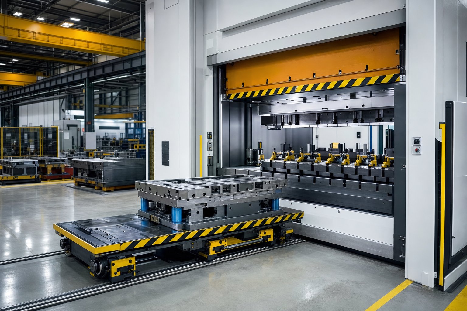
Integrating Die Clamps with Quick Die Change Workflows
Single-minute exchange of dies sounds great in a lean manufacturing seminar. But when you walk back to the press floor and face a 400-ton straightside with strap clamps on every die, the gap between theory and reality is measured in minutes of lost production. The truth is straightforward: your clamping technology is the single largest variable determining whether quick die change stays a concept or becomes an operational fact. Die clamps for quick die change must deliver two things simultaneously - reliable holding force and minimal time between the last good part from die A and the first good part from die B.
How Clamping Technology Determines Changeover Speed
Consider what happens during a typical manual changeover. The press technician loosens six to twelve strap clamps, slides out the T-bolts, removes step blocks, rolls the die out, positions the new die, reinstalls all hardware, tightens in sequence, torque-verifies, and runs test strokes. Even a skilled setter working without interruption spends 15 to 30 minutes just on clamping and unclamping. Multiply that across three die changes per shift, and you have burned an hour or more of press uptime on fastener work alone.
Hydraulic systems collapse that timeline dramatically. With pre-positioned clamps actuated by a single control valve, the operator presses a button and all clamps engage or release simultaneously. Actual clamp and unclamp time drops to seconds, though total changeover still includes die positioning, alignment verification, and connection of auxiliary systems. Realistic total changeover ranges for hydraulic quick die change systems fall between 1 and 5 minutes depending on die size and complexity.
Magnetic platens push further. Because clamping and unclamping require only a brief electrical pulse - roughly two seconds of electrical power to transition from unclamped to fully clamped - the fastening step essentially disappears from the changeover sequence. The die rolls into position, the operator activates the magnetic field, and the press is ready to run. Total changeover times under one minute become achievable when combined with rolling bolsters or die carts.
| Clamping Method | Clamp/Unclamp Time | Typical Total Changeover | Operator Skill Dependency | SMED Feasibility |
|---|---|---|---|---|
| Manual Strap Clamps | 8-20 min | 15-45 min | High (torque, sequence, placement) | Unlikely without subplates |
| Hydromechanical Clamps | 3-8 min | 5-15 min | Moderate (positioning, low torque) | Possible with standardization |
| Hydraulic Quick-Release | 5-30 sec | 1-5 min | Low (push-button actuation) | Yes |
| Magnetic Platens | 2-3 sec | 0.5-3 min | Very Low (automated activation) | Yes |
The difference between the top and bottom of this table is not incremental. It is the difference between a shop that can economically run lot sizes of 500 and one locked into 5,000-piece minimums just to amortize changeover downtime.
Standardizing Die Design for Faster Clamping
Faster clamping hardware alone does not guarantee quick die change. If every die in your rack has a different shut height, footprint, and clamping ledge location, even hydraulic clamps require repositioning and height adjustment at each changeover. That adjustment time erodes the speed advantage you paid for.
Die standardization eliminates those variables. Standardizing characteristics such as shut height, clamping height, clamping location, pass height, and die location on progressive dies is the first step to implementing quick die change, and it can be accomplished in a company's own machine shop. When clamps always land in the same position at the same height, you remove the decision-making and adjustment that consume setup time.
For shops with hundreds of legacy dies where full standardization is impractical, subplates offer a realistic middle ground. A subplate of uniform dimensions bolts to the bottom of each die, giving every tool the same clamping height, the same roller contact surface, and the same locator pin pattern regardless of the actual die shoe geometry sitting on top of it. Hydraulic clamps stay in fixed positions on the bolster and engage the subplate edges identically every time. Some shops prioritize subplating only the 20 percent of dies that run 80 percent of the time, then use pre-staged separate subplates for the remainder.
Die parallels also contribute. They standardize shut height and pass height while leaving clearance beneath the die for scrap conveyors, making the die compatible with both quick clamping and automated scrap removal in one setup.
Retrofit Considerations for Existing Presses
Most stampers are not buying new presses just to get better clamping. They need quick die change systems that bolt onto existing equipment. Whether a retrofit works depends on three physical compatibility factors:
- T-slot dimensions: Hydraulic clamps that slide into T-slots must match the slot width and depth already machined into your bolster and ram. Standard slot widths (5/8", 3/4", 1", 1-1/4") vary by press manufacturer and vintage. Measure your actual slots before specifying any sliding clamp system.
- Bolster thickness and flatness: Magnetic platens bolt directly to the bed and slide surfaces. The bolster must be thick enough to accept the mounting fasteners without compromising structural integrity, and flat enough (typically within 0.002" per foot) to ensure full magnetic contact. Worn or dished bolsters may need resurfacing before a magnetic system can function at full rated force.
- Hydraulic supply requirements: Hydraulic clamping systems need a power unit delivering 3,000 to 5,000 PSI with adequate flow for the number of clamps. Some presses already have hydraulic circuits for overload protection or die cushions that can be tapped. Others require a standalone pump, reservoir, and control valve package mounted externally.
- Control integration: Modern quick die change systems interlock with the press control to prevent stroking when clamps are not confirmed engaged. Your existing press control must accept these interlock signals, which may require a PLC upgrade on older mechanical presses with relay-based controls.
A practical evaluation starts with a physical survey: slot dimensions, bolster condition, available hydraulic capacity, and press control architecture. Bolt-on track designs that do not require machining the press bed or breaking up the floor have expanded retrofit options significantly, making rolling bolster and automated clamping systems accessible to presses that were never originally designed for them.
It is also common to mix technologies within a single press. Hydraulic swing clamps on the slide - where manual torquing overhead is awkward and inconsistent - paired with hydromechanical clamps on the rolling bolster where hoses might interfere with die cart travel. The right quick die change configuration often is not a single system but a combination tailored to the physical constraints of each press.
Compressing changeover time solves the production scheduling problem. But faster clamping cycles also mean clamps cycle more frequently, accelerating wear on seals, threads, and contact surfaces. That increased duty cycle shifts attention toward another dimension entirely: how often each clamp type needs inspection, what wear looks like before it becomes failure, and which compliance standards govern the whole process.
Maintenance Schedules and Safety Compliance
A clamp that held perfectly during last month's production run does not guarantee it will hold today. Threads wear. Seals degrade. Contact surfaces develop micro-cracks invisible to a casual glance. Yet most shops treat die clamps as install-and-forget hardware, inspecting them only after something has already gone wrong. A structured die clamp maintenance schedule catches degradation early, before a worn fastener or leaking seal translates into a die shift, damaged tooling, or an operator injury.
Routine Inspection Checklist by Clamp Type
Different clamping technologies degrade through different mechanisms, so a single generic checklist fails to cover all systems. Your die clamp inspection checklist should be organized by clamp category, with tasks and intervals calibrated to how each type actually wears under cyclical press loading.
Manual clamps (strap, toe, swing, and hydromechanical types):
- Inspect T-bolt threads for stretching, galling, or cross-threading at every die change
- Check strap and toe bodies for hairline cracks at the bolt hole and contact edges weekly
- Verify step block contact surfaces for mushrooming, rounding, or surface deformation weekly
- Clean all contact faces of oil, stamping lubricant, and metal debris before each installation
- Measure T-bolt diameter at the thread root with a micrometer monthly - any reduction exceeding 0.005 inches indicates fatigue wear
- Test hydromechanical indicator pins for full extension at target torque - a pin that fails to extend fully signals internal piston seal wear
- Inspect hex heads and nut flats for rounding - replace any fastener that shows wrench slippage damage
Hydraulic clamps:
- Verify system pressure holds at the rated value for a minimum of 15 minutes with the pump off - any pressure drop indicates internal leakage past piston seals
- Check all external hose connections and fittings for weeping or active drips at each shift start
- Inspect piston rod surfaces for scoring, pitting, or chrome flaking monthly
- Perform hydraulic fluid analysis quarterly - particle count, viscosity, and water content per ISO 4406 cleanliness standards
- Replace filter elements at bypass indicator trigger or at the scheduled interval, typically every 500 to 2,000 operating hours
- Inspect directional control valves and pilot-operated check valves for response time and internal leakage annually
Magnetic clamping systems:
- Verify magnetic field strength using a calibrated pull-test gauge quarterly - compare to the baseline reading recorded at installation
- Inspect platen surfaces for scratches, gouges, or embedded debris that could create air gaps before each die set
- Clean bolster and slide magnetic surfaces with a non-abrasive cleaner at every changeover
- Check electrical coil resistance and activation pulse current annually - deviations beyond 10% of specification indicate coil degradation
- Verify proximity sensor function - sensors must detect air gaps greater than 0.007 inches and prevent press activation
Wear Indicators and Replacement Criteria
Inspection tells you the current condition. Replacement criteria tell you when current condition has crossed the line from acceptable to unsafe. Unlike many tooling components that gradually produce worse parts before failing, a clamping fastener often works perfectly until the moment it does not. That binary failure mode makes defined replacement triggers essential rather than optional.
For manual hardware, replace any T-bolt or nut that shows:
- Visible thread deformation or thread crest flattening from repeated tightening cycles
- Permanent elongation - measurable as a length increase beyond the original specification, even if only a few thousandths of an inch
- Cracks at the transition radius between the bolt head and shank
- Corrosion pitting that removes more than 5% of the original cross-sectional area at any point along the threaded length
- Rounded hex flats that prevent the torque wrench from seating fully
For hydraulic systems, hydraulic clamp seal replacement is the most common preventive action. Schedule seal kits based on operating hours rather than calendar time. A clamp cycling 300 times per shift in a three-shift operation accumulates wear far faster than one cycling 20 times per day. Typical seal life ranges from 500,000 to 2,000,000 cycles depending on system pressure, fluid cleanliness, and operating temperature. When monthly fluid sampling shows rising particle counts or case drain flow increases by 25% or more above baseline, those signals indicate internal wear has progressed beyond the seal replacement window into potential piston or bore damage.
Magnetic platens rarely require component replacement but demand surface maintenance. A platen with a surface flatness deviation exceeding 0.004 inches per foot should be reground. Deep scratches that cannot be removed by lapping reduce effective contact area and weaken holding force proportionally.
Safety Compliance and Documentation
Die clamping is not merely a tooling concern - it is a safety-critical system governed by enforceable standards. The ANSI B11 series standards (including B11.1 for mechanical presses, B11.2 for hydraulic presses, and B11.20 for integrated manufacturing systems) establish the framework for risk assessment, safeguarding, and documentation of hazardous-energy control in press operations. OSHA's General Duty Clause (Section 5(a)(1)) requires employers to maintain workplaces free of recognized hazards - and a die clamp known to be worn, improperly torqued, or past its service life qualifies as exactly that kind of recognized hazard.
What does compliance look like in practice? It means documentation that proves you performed the right inspections at the right intervals and took action when results warranted it. For safety audits, maintain:
- Dated inspection records for every clamp and fastener, tied to a specific press and die setup
- Torque verification logs showing values achieved at installation and re-check after initial press strokes
- Hydraulic system pressure test records with pass/fail criteria and technician sign-off
- Magnetic field strength test results compared against the baseline specification
- Replacement records documenting which fasteners were retired, the reason for retirement, and the replacement hardware specification
- Risk assessment documentation per ANSI B11.20 for any press where alternative methods of hazardous-energy control are used in lieu of full lockout during die setting tasks
The ANSI B11.20 standard specifically addresses the shared-space concept in press operations - situations where personnel interact with equipment during setup tasks that cannot always be completed under full lockout conditions. Die clamping falls squarely within this scope. The standard requires a documented task-based risk assessment, verification of safety control system performance, and validation testing to confirm that interlocks and alternative controls provide protection equivalent to lockout.
A practical approach is to structure your maintenance documentation by asset. Each press gets a clamping maintenance file containing all inspection records, replacement logs, and risk assessment documents. Digital systems make retrieval instant during an audit. Paper-based systems work if they are rigorously maintained, but the reality in most pressrooms is that paper records deteriorate, get filed incorrectly, or simply stop being completed under production pressure. Whatever system you choose, the key principle is traceability: any auditor or investigator should be able to trace the maintenance history of every clamping component on a specific press back through its entire service life.
Maintenance keeps your clamps functional. But clamp performance also depends on something established much earlier in the process - how the die itself was designed. Clamp placement, access clearance, and interference with lifters or scrap paths are all decisions that get locked in during die engineering, long before the first setup technician ever reaches for a T-bolt.
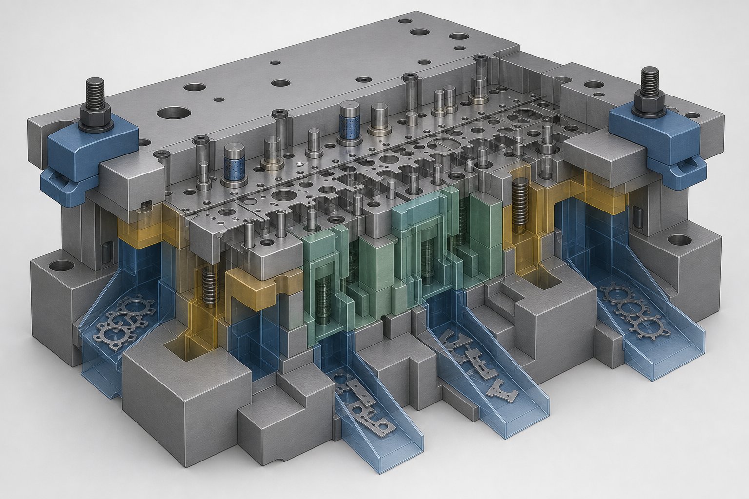
How Clamping Connects to Die Design and Material Flow
Clamp placement is rarely a last-minute decision that works out well. When a die designer treats clamping as an afterthought, the setup technician inherits a puzzle: clamps that collide with lifter rails, bolts that block scrap chutes, or access points so tight that a torque wrench physically cannot reach the fastener. The best die clamp placement design happens inside the CAD model, not on the press floor during first tryout.
How Clamp Placement Interacts with Die Components
A stamping die is a dense assembly of interdependent components, and every one of them competes for the same perimeter real estate where clamps need to land. Imagine placing a strap clamp directly over a nitrogen-spring lifter pocket. The clamp contact point sits exactly where the lifter rod must travel vertically. On the return stroke, stamping die lifters push upward against the strip, and any obstruction in their path either restricts lifter travel or takes the impact load the lifter was designed to deliver to the strip.
Material flow paths create similar conflicts. In progressive dies, the strip feeds laterally through the die. Feed height, pilot locations, and bypass notches all occupy specific positions along the die shoe edges. A clamp positioned over a bypass notch can deform the notch relief, changing strip feed behavior and creating misfeed conditions. Scrap chutes route slugs and trim scrap downward through openings in the lower shoe and bolster. Block one of those chutes with a clamp or step block, and scrap accumulates inside the die, eventually jamming the tool or damaging forming surfaces.
Sensors add another layer. Misfeed detectors, strip end sensors, and part-out proximity switches mount along the die perimeter. Their wiring harnesses route outward to connectors. A clamp positioned over a sensor cable subjects it to compression damage every time the fastener is torqued.
Designing Clamping Access into the Die Structure
The solution is not avoiding clamps near these features. It is designing dedicated clamping zones into the stamping die component layout from the start. Tooling engineers who account for die clamping access clearance during initial design eliminate the interference problems that plague retrofit situations.
Key design considerations that affect clamp selection and placement:
- Locate clamping ledges away from lifter pockets - maintain a minimum clearance of 1.5 times the lifter stroke between the clamp contact zone and the nearest lifter centerline
- Route scrap chutes toward the center or rear of the die, keeping die shoe edges clear for clamp access on at least three sides
- Design die shoe overhangs (clamping ears) that extend beyond the functional envelope of punches, pilots, and sensors
- Standardize clamping ledge height across die families so the same step block and clamp set works without adjustment
- Specify flat, ground clamping surfaces on die shoes - unfinished or as-cast surfaces reduce friction and effective clamping force
- Avoid placing dowel pins or key slots within the footprint where a T-bolt head must slide into position
- Account for wrench swing arc - if an operator cannot rotate a torque wrench 30 degrees at the fastener location, that clamp point is functionally inaccessible
This principle aligns with what stamping expert Thomas Vacca calls designing in the maintenance process. If you do not plan how the die will be clamped, unclamped, and serviced, you cannot guarantee those tasks will be performed accurately and repeatably. A die that runs beautifully but takes 45 minutes to clamp because every access point conflicts with an internal component defeats the purpose of good tooling design.
For complex progressive dies where lifters, cam units, material flow, and clamping strategy must all coexist within a tight footprint, the integration challenge intensifies quickly. Engineers facing these conflicts benefit from working with tooling partners who coordinate die structure decisions holistically. YICHEN's custom stamping die solutions address exactly this intersection - resolving how clamping access, lifter placement, bypass geometry, and component layout work together rather than against each other from the earliest design stage.
Getting the die design right ensures that clamps can physically reach where they need to go. But deciding which clamping technology belongs on a given press - and justifying that decision with documented criteria rather than gut feel - requires a structured evaluation framework that weighs press type, changeover frequency, production targets, and budget together.
Structured Decision Framework for Choosing the Right Die Clamping System
Most shops choose their clamping system the same way they chose it twenty years ago: whatever was already on the press when they bought it, or whatever the last supplier quoted. That approach worked when changeover frequency was low and labor was cheap. It does not work when your scheduling demands shorter runs, higher uptime, and zero tolerance for die shift. A proper die clamp selection guide replaces habit with documented criteria, making the decision traceable, defensible, and repeatable across your entire press fleet.
Decision Criteria Matrix for Clamping System Selection
Four variables drive the choice. Press type and tonnage define what forces the clamps must resist. Die change frequency determines how much time you lose to clamping activities per shift. Production volume and uptime targets set the financial threshold where faster changeover pays for itself. And capital budget determines which technologies are accessible today versus which require phased investment. The matrix below maps each variable against clamping technologies to clarify where each system fits best.
| Decision Criteria | Manual Strap Clamps | Hydromechanical | Hydraulic Quick-Release | Magnetic Platens |
|---|---|---|---|---|
| Press tonnage under 200 tons | Excellent | Good | Adequate (often oversized) | Adequate (often oversized) |
| Press tonnage 200-800 tons | Adequate | Good | Excellent | Excellent |
| Press tonnage over 800 tons | Poor (too many clamps needed) | Adequate | Excellent | Excellent |
| Die changes fewer than 2 per shift | Acceptable | Good | Over-invested | Over-invested |
| Die changes 3-6 per shift | Poor (excessive downtime) | Adequate | Excellent | Excellent |
| Die changes more than 6 per shift | Unacceptable | Poor | Good | Excellent |
| Uptime target above 85% | Difficult to sustain | Achievable with discipline | Easily achievable | Easily achievable |
| Capital budget under $5,000 per press | Only option | Feasible | Not feasible | Not feasible |
| Capital budget $5,000-$30,000 per press | Available | Available | Feasible for single-press | Not feasible |
| Capital budget over $30,000 per press | Available | Available | Available | Feasible |
Read this table as a filter, not a score. If your press runs above 800 tons with six die changes per shift and an 85% uptime target, manual strap clamps fail on three of four criteria. The matrix narrows your options objectively before supplier conversations begin.
Matching Technology to Operational Requirements
Choosing a die clamping system is not purely a financial calculation. Operational constraints shape the decision just as strongly as budget. A high-speed progressive die running advanced high-strength steel at 300 strokes per minute generates dynamic loads that demand the clamping force consistency only hydraulic or magnetic systems provide. A job shop running 30 different dies per week on a 150-ton OBI press benefits more from swing clamps and hydromechanical units that improve consistency without requiring infrastructure changes.
Consider these operational realities when narrowing options:
- Die material compatibility: Magnetic platens require ferromagnetic die shoes. Aluminum die holders or non-magnetic stainless steel subplates will not work. Verify your die shoe material before specifying magnetics.
- Press orientation: Hydraulic clamps on the ram (upper die) must hold against gravity during die loading. Systems rated for horizontal bolster use may not have adequate holding force for vertical slide mounting without recalculation.
- Environmental conditions: Presses running heavy lubrication or coolant spray degrade manual clamp friction rapidly. Hydraulic systems with external hoses in that environment face accelerated fitting corrosion. Magnetic platens handle wet environments well as long as surfaces are wiped clean at changeover.
- Operator skill level: Manual systems demand training and discipline around torque specs and tightening sequence. Hydraulic and magnetic systems reduce operator dependency but require maintenance technicians trained on those specific technologies.
Where to Start When Upgrading Your Clamping Strategy
A die clamp upgrade for stamping press operations does not need to happen all at once. Modular, phased implementation lets you prove the ROI on one press before committing across the floor. Follow this evaluation sequence:
- Audit your current state. Log changeover times, clamp-related incidents, and torque verification failures across all presses for 30 days. This baseline data identifies which presses have the greatest improvement potential.
- Identify your constraint press. The press with the most frequent die changes and highest downtime cost is your starting point. Upgrading this press first delivers the fastest payback.
- Assess physical compatibility. Measure T-slot dimensions, bolster flatness, available hydraulic supply, and press control architecture on the target press. These measurements determine which technologies are retrofit-feasible without structural modifications.
- Calculate payback period. Compare the cost of the clamping upgrade against the production value of recovered uptime. A press billing $200 per hour of production that recovers 45 minutes per shift pays back a $25,000 hydraulic system in under six months.
- Pilot and validate. Install the selected system on the constraint press. Run for 60 to 90 days. Measure actual changeover time reduction, verify clamping force consistency, and document any installation or maintenance issues.
- Standardize and expand. Use pilot results to build the business case for fleet-wide deployment. Prioritize presses by changeover frequency and production value, upgrading highest-impact equipment first.
This sequence keeps risk contained while building organizational confidence in the new technology. Each step generates data that informs the next decision rather than requiring a leap of faith across the entire operation.
For operations where die complexity adds another variable - progressive dies with tight clamping clearances, lifter interference, or non-standard shoe geometries - the clamping upgrade often cannot be separated from die design modifications. Clamping ledges may need to be added, subplates designed, or shoe dimensions standardized across a die family. In these situations, working with a tooling partner who understands both the die structure and the clamping integration challenge from the start prevents costly rework. YICHEN's custom stamping die solutions serve engineers navigating exactly this transition - coordinating die structure, component layout, and clamping access so the upgrade works as a system rather than a collection of mismatched parts.
Frequently Asked Questions About Stamping Die Clamps
1. How much clamping force do I need for my stamping press?
For crank presses, total clamping force should equal at least 10% of rated machine tonnage. For high-speed presses, use 20% of rated tonnage. Split this force evenly between upper and lower die halves. When using strap clamps with step blocks, remember that only about half the bolt tension acts on the die, so you must double your calculated preload requirement. Add nitrogen-spring lifter forces directly to your upper die clamping requirement, as these forces work against the clamps during the return stroke.
2. What is the difference between hydraulic die clamps and magnetic clamping systems?
Hydraulic die clamps use pressurized fluid acting on pistons to generate clamping force, requiring an external power unit and delivering clamp/unclamp times of 5 to 30 seconds. Magnetic clamping systems use electropermanent magnets that activate in 2 to 3 seconds with a brief electrical pulse and hold without continuous power. Hydraulic systems work with any die material but need ongoing seal maintenance and fluid analysis. Magnetic platens require ferromagnetic die shoes and flat, clean contact surfaces but have virtually no mechanical wear components. Magnetic systems typically cost more upfront but offer the fastest changeover times.
3. How often should stamping die clamps be inspected and replaced?
Manual clamp T-bolt threads should be inspected at every die change for stretching or galling, with monthly micrometer measurements to detect fatigue wear. Replace any bolt showing permanent elongation, cracks at the head-to-shank radius, or thread deformation. Hydraulic clamp seals typically last 500,000 to 2,000,000 cycles depending on pressure and fluid cleanliness, with quarterly fluid analysis guiding replacement timing. Magnetic platens need surface inspection before each die set and quarterly pull-test verification against the installation baseline reading.
4. Can I retrofit quick die change clamps onto an existing stamping press?
Yes, most quick die change clamping systems are designed for retrofit installation. Compatibility depends on three factors: T-slot dimensions must match the sliding clamp specifications, bolster thickness and flatness must support the mounting method (magnetic platens need flatness within 0.002 inches per foot), and hydraulic supply must deliver 3,000 to 5,000 PSI with adequate flow. Bolt-on track designs that avoid machining the press bed have expanded retrofit options significantly. Older presses with relay-based controls may also need a PLC upgrade to accept clamp interlock signals.
5. Why does my die shift during production even though the clamps are tight?
Die shift under apparently tight clamps typically stems from one of several root causes: oil or stamping lubricant on the die shoe surface reducing friction by 30 to 50%, mismatched step block height causing the strap clamp to tilt and concentrate force at the bolt rather than the die edge, bolt relaxation from thermal cycling during long runs, or insufficient total clamping force for the dynamic loads involved. Off-center loading in progressive dies also creates tilting moments that overload clamps on one side. Start by cleaning contact surfaces, verifying step block height match, re-torquing after initial press strokes, and recalculating whether your total clamp force accounts for stripping forces, lifter loads, and snap-through shock.


