


What Stamping Press Dies Are and Why They Matter
Every metal part you touch started as a flat sheet. The thing that turned it into a bracket, connector, or panel was a stamping press die. If you're asking what is a stamping die and why it deserves your attention, here's the short answer: it's the single tooling decision that determines whether your parts come out right or wrong, fast or slow, cheap or expensive.
What Is a Stamping Press Die
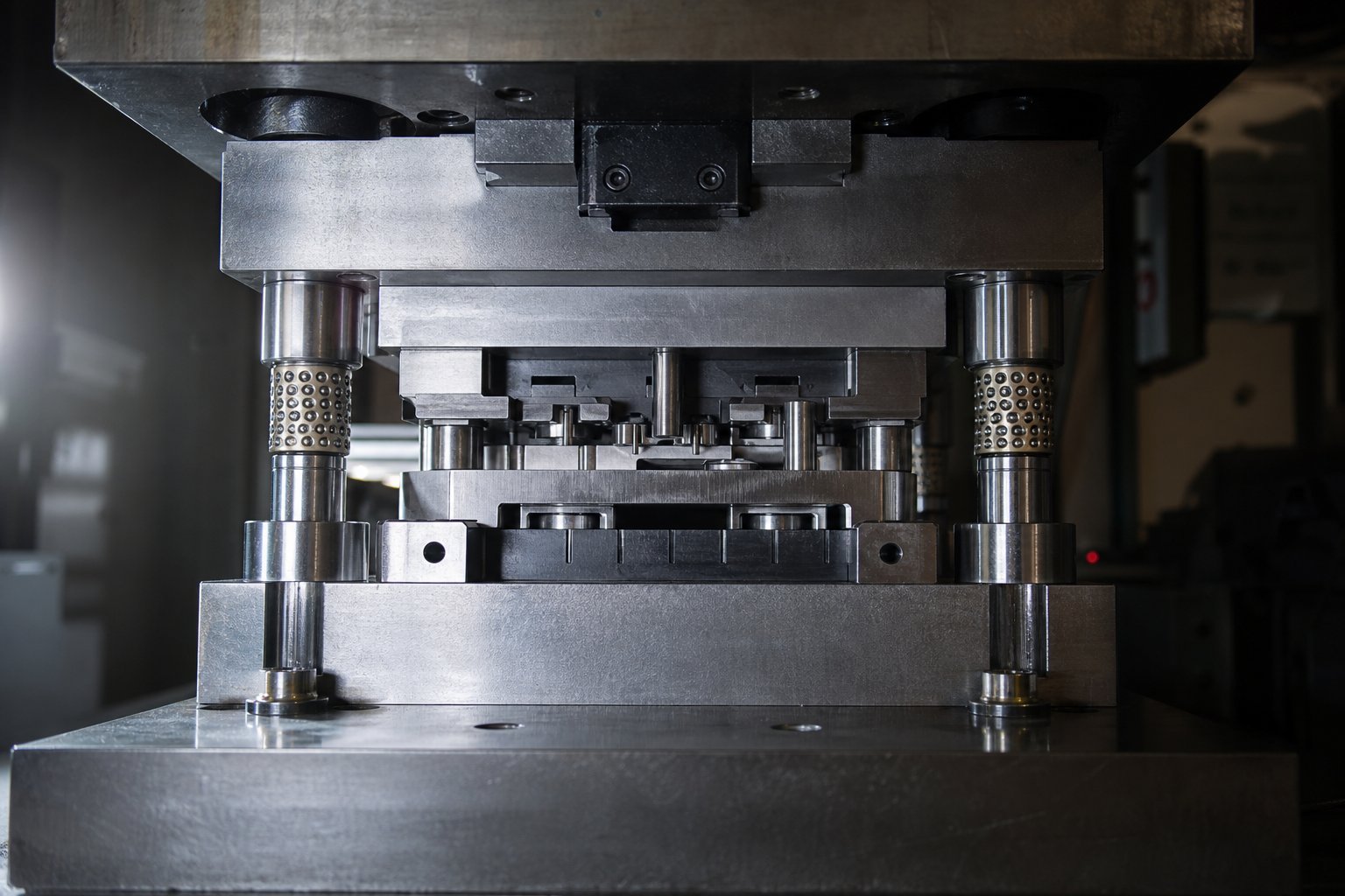
A stamping die is a specialized precision tool made from hardened tool steel or carbide that cuts, bends, draws, or forms sheet metal into a finished part. It consists of matched upper and lower halves - collectively called a die set - that work together inside a press. When the press cycles, the upper half descends into the lower half, and the metal between them takes the shape dictated by the die's geometry. The stamping definition in manufacturing always comes back to this core concept: controlled force applied through precision tooling to transform flat stock into three-dimensional components.
A stamping press die is precision tooling consisting of matched upper and lower halves that cut, form, or shape sheet metal into finished parts by applying controlled force through a mechanical or hydraulic press.
How Stamping Dies Fit Into the Manufacturing Process
Imagine a press without a die installed. You have a machine capable of delivering hundreds of tons of force, but it produces nothing. The press provides energy; the die provides intelligence. What are dies, really? They're the geometry translators that convert raw press force into specific part features - holes, bends, contours, and drawn shapes.
This relationship matters because the die defines every quality attribute of the finished piece: dimensional accuracy, edge condition, surface finish, and structural integrity. A press running at 600 strokes per minute means nothing if the stamping dies inside it produce parts with excessive burrs or inconsistent dimensions. Production efficiency and part quality both live or die inside the tooling.
That's why choosing the right die type for your application is not a secondary decision - it's the decision that shapes everything downstream, from cycle time to scrap rate to total cost per part.
Types of Stamping Dies and When to Use Each
Die type selection is where cost, speed, and part complexity collide. Pick a die that's too simple for your geometry and you'll fight quality issues every shift. Over-engineer the tooling for a short run and you'll never recoup the investment. Understanding the types of stamping dies - and matching each to the right production scenario - keeps both problems off your shop floor.
Single-Station Dies for Low-to-Medium Volume
Single-station dies perform one operation per press stroke. They're the workhorses for straightforward jobs and lower production volumes. You'll encounter several common varieties:
- Blanking die - cuts a flat shape (the blank) from sheet metal. The cut piece is your part; the remaining skeleton is scrap. Ideal when you need clean outlines as a starting point for further operations.
- Piercing die - punches holes, slots, or openings into the workpiece. Think of punching stamping operations that create mounting holes or ventilation patterns.
- Forming die - bends or shapes metal without removing material. A forming die handles flanges, channels, and contoured surfaces where geometry changes but material stays intact.
- Drawing die - pulls sheet metal into a cavity to create hollow, cup-shaped parts like housings or enclosures.
The trade-off with single-station stage tooling is straightforward: lower tooling cost and simpler setup, but slower throughput. If a part needs four operations, the workpiece moves through four separate presses or setups. That handling time adds up quickly at higher volumes.
Progressive Dies for High-Volume Production
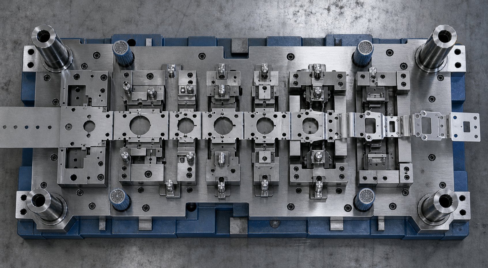
When volume climbs and parts get complex, progressive dies change the economics entirely. A coil of strip material feeds into the press and advances through multiple stations - each performing a different operation like blanking, piercing, bending, or forming. The part stays connected to the strip carrier until the final station cuts it free.
Why does this matter? A progressive die can produce a finished part every stroke, sometimes running at 400 to 1,200 strokes per minute. You get speed, consistency, and minimal handling between operations. Common die stamping examples include electrical connectors, brackets, and contact springs - parts with tight tolerances that need multiple features formed in precise sequence.
The downside: progressive dies cost more upfront and require skilled die designers. They also demand presses with sufficient bed size to house all stations in a single tool.
Transfer Dies and Compound Dies
Some parts are simply too large or too deep-drawn to stay on a strip. That's where transfer stamping comes in. The blank is cut free early, then a mechanical transfer system moves it from station to station for successive operations. Frames, structural shells, and large enclosures are typical transfer die applications. You get the multi-operation capability of progressive tooling with the flexibility to handle bigger, more complex geometries.
Compound dies take a different approach. They perform multiple cutting operations - like blanking and piercing - in a single stroke at one station. They're faster than running separate simple dies but limited to cutting operations; forming isn't part of their repertoire. When you need flat parts with precise hole patterns produced at moderate-to-high volume, compound dies hit the sweet spot between cost and speed.
| Die Type | Best For | Typical Volume | Relative Cost | Part Complexity |
|---|---|---|---|---|
| Single-Station (Simple) | Basic blanking, piercing, or forming | Low to medium | Low | Simple |
| Compound | Multiple cut operations in one stroke | Medium to high | Moderate | Moderate (cutting only) |
| Progressive | Complex parts needing multiple operations | High | High | High |
| Transfer | Large or deep-drawn parts across stations | Medium to high | High | High |
Notice the pattern: as part complexity and volume increase, tooling investment rises - but per-piece cost drops. The economics of die selection always involve balancing that upfront capital against long-term production efficiency. A progressive die costing $80,000 looks expensive until you calculate the per-part savings over a million-piece run compared to shuffling workpieces between four single-station setups.
The die type defines throughput, but it doesn't guarantee quality on its own. What happens inside the die - the components that guide, cut, strip, and align - determines whether those parts actually meet spec stroke after stroke.
Critical Components Inside a Stamping Die Set
Knowing your die type is half the equation. The other half lives in the individual components that make each stroke repeatable. When a stamping die produces its ten-thousandth part with the same edge quality as the first, that consistency traces back to precisely engineered internals working together under extreme force. Here's what each one does - and what goes wrong when it wears.
Die Shoes, Guide Pins, and Alignment Systems
The upper and lower die shoes form the structural backbone of every die set. These are precision-machined steel or aluminum plates that everything else mounts to - punches, die blocks, strippers, springs, and sensors. According to The Fabricator, die shoe thickness depends on the expected cutting and forming forces. A coining die that squeezes metal under compression needs a much thicker die plate than a simple bending die because the load distribution demands it.
Guide pins (also called guide posts) and bushings connect the upper and lower die shoes and ensure they align within tolerances as tight as 0.0001 inches. Two main types exist: friction-style pins that ride in aluminum-bronze bushings, and ball-bearing pins that use hardened steel ball cages for reduced friction at higher speeds. When guide pins wear or deflect, the upper and lower halves shift relative to each other. Even a few thousandths of misalignment causes punch-to-die offset, which shows up immediately as uneven burrs, dimensional drift, and accelerated cutting edge wear.
Heel blocks add another layer of stability. These precision-machined steel blocks absorb side thrust generated during cutting or forming, preventing lateral forces from overwhelming the guide pins. Without them, one-directional forces can deflect the entire upper shoe - a subtle failure that ruins part geometry before anyone notices the root cause.
Punches, Die Blocks, and Cutting Geometry
The press die punch is the component that actually contacts the sheet metal and forces it into or through the die block opening. Punches and dies work as a matched pair: the punch pushes material through the die block aperture, and the gap between their cutting edges - the clearance - determines everything about cut quality.
Clearance is typically expressed as a percentage of material thickness per side. A 10% clearance means the gap at each edge equals 10% of the stock thickness. Get it right, and the fracture planes from the top and bottom of the material align cleanly, producing a smooth cut with minimal burr. Too tight, and excessive force accelerates punch wear, increases energy consumption, and can fracture tooling. Too loose, and the material tears instead of shearing - leaving heavy burrs and ragged edges that require secondary finishing.
Die block geometry varies by operation. A blanking die block has an opening sized to the desired part outline, while a punching die block is sized to the hole being created. For forming operations, die blocks incorporate radii and relief angles that control how material flows during bending or drawing. Harder, stronger workpiece materials demand wider clearances because their fracture behavior under shear differs from softer metals like aluminum.
Strippers, Pilots, and Material Control
After each stroke, elastic recovery and friction cause the sheet metal to grip the punch as it retracts. Without intervention, the workpiece rides upward with the punch - jamming the die and damaging both the tooling and the part. That's the job of the stripper plate: it holds the material down against the die surface while the punch withdraws, cleanly separating the two every cycle.
Pilots handle a different problem. In progressive dies, the strip must advance to exactly the right position before each stroke fires. Pilot pins - extending through the stripper plate - enter previously pierced holes in the strip and lock its location before any cutting or forming begins. Without accurate pilot registration, features drift from station to station, compounding dimensional error across the finished part.
Here's how these stamping die components interact - and what happens when each one degrades:
- Die shoes - provide mounting foundation and distribute press force. When worn or warped: components shift, causing progressive misalignment across all stations.
- Guide pins and bushings - maintain upper-to-lower alignment within 0.0001". When worn: dimensional errors, uneven cutting, and accelerated punch wear.
- Die punches - penetrate material to cut or form features. When chipped or worn: burrs increase, hole sizes drift, and press tonnage rises.
- Die blocks - provide the mating cutting edge and support material during forming. When worn: clearance increases, edge quality deteriorates, slugs pull back through the die.
- Stripper plates - remove material from the punch after each stroke. When worn or weak springs: parts stick, strips misfeed, and cycle interruptions spike.
- Pilots - locate the strip precisely before each stroke. When worn or bent: progressive feature-to-feature accuracy degrades, producing out-of-spec parts.
Every one of these components is a wear item. The materials they're built from - and how those materials are heat-treated, coated, and machined - directly determine how many good parts you get before maintenance or replacement becomes unavoidable.
Die Materials, Coatings, and Construction Methods
The steel grade inside your tooling die determines whether it lasts 50,000 hits or 5 million. Yet die material selection rarely gets the attention it deserves - most sourcing decisions focus on geometry and delivery time while treating material as an afterthought. That's a costly mistake. The stamping die steel you specify controls wear rate, maintenance frequency, and ultimately cost-per-part over the entire production life of the tool.
Tool Steel Grades and Their Applications
Not all die tools are built from the same metal. Choosing the right grade means balancing three competing demands: hardness (resists wear), toughness (resists chipping and cracking), and machinability (keeps die manufacturing costs manageable). Here's how the most common grades stack up for stamping applications:
- D2 (Cold-Work, High-Carbon High-Chromium) - Hardness: 62-64 HRC. Exceptional wear resistance from hard chromium carbides. Best for long-run blanking and piercing dies stamping abrasive materials like stainless steel and high-strength low-alloy grades. The go-to choice when die life is the priority.
- A2 (Air-Hardening) - Hardness: 63-65 HRC. Offers strong wear resistance with better toughness than D2, plus excellent dimensional stability during heat treatment. Ideal for blanking and forming punches where tight tolerances must survive hardening without distortion.
- M2 (High-Speed) - Hardness: 62-64 HRC. Retains hardness at elevated temperatures, making it suitable for high-speed progressive dies where friction generates significant heat at cutting edges. Often used for punches running at 800+ strokes per minute.
- S7 (Shock-Resisting) - Hardness: 60-62 HRC. High impact toughness at the expense of some wear resistance. The right pick for heavy forming dies, coining operations, and any tooling die subjected to repeated mechanical shock that would chip a harder, more brittle steel.
- Carbide (Tungsten Carbide) - Hardness: 75-80+ HRA (roughly equivalent to 90+ on converted scales). Extreme wear resistance for the highest-volume applications stamping abrasive or thin materials. Significantly more expensive and brittle - typically used as inserts in critical wear areas rather than full die blocks.
The pattern is clear: harder steels resist wear but crack under shock, while tougher steels absorb impact but wear faster. A metal die running 200,000 parts per year in mild steel might perform well in A2, but the same geometry stamping stainless at 2 million parts annually demands D2 or carbide inserts. Production volume and workpiece material drive the decision - not personal preference or habit.
Heat Treatment, Surface Coatings, and EDM Processes
Raw tool steel isn't ready for die service until heat treatment transforms its microstructure. The process involves heating to specific austenitizing temperatures (ranging from 1,475 degrees F for O1 up to 2,250 degrees F for M2), then controlled cooling through quenching - in air, oil, or water depending on the grade. Tempering follows, reducing brittleness while retaining target hardness. Getting this sequence wrong means a die that either chips on its first production run or wears prematurely because it never reached full hardness.
Surface coatings add another layer of protection beyond what base steel provides. Applied through Physical Vapor Deposition (PVD), these thin-film coatings dramatically extend die life without changing part dimensions:
- TiN (Titanium Nitride) - High hardness, good wear and oxidation resistance. The most common general-purpose die coating, suitable for most cutting and forming operations.
- TiCN (Titanium Carbonitride) - Lower friction and higher toughness than TiN. Performs well in environments demanding reduced galling, particularly when stamping aluminum or stainless.
- DLC (Diamond-Like Carbon) - Extremely low friction coefficient with strong wear resistance. Used on forming die surfaces where material flow and surface finish are critical, especially for non-ferrous metals.
Die machining brings these materials into their final geometry. CNC milling and turning remove bulk material to rough dimensions, followed by precision grinding to achieve tolerances within microns. But some die geometries - sharp internal corners, complex contour profiles, narrow slots - push beyond what conventional cutting tools can produce.
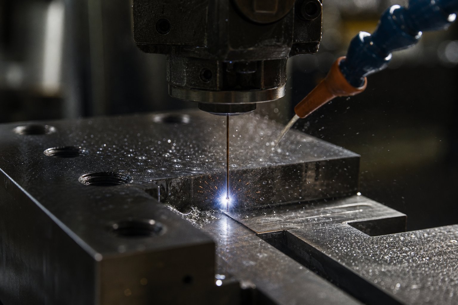
That's where EDM enters the picture. Wire EDM uses a thin electrically charged wire to cut through hardened die steel with micron-level accuracy, regardless of material hardness. Because the wire never physically contacts the workpiece, there's no mechanical stress or tool deflection - critical when machining dies that demand ±0.005 mm tolerance on complex profiles. Sinker EDM complements wire EDM by using shaped electrodes to create blind cavities, 3D contours, and intricate pocket geometries that neither milling nor wire cutting can reach.
The die tooling construction sequence typically flows from CNC roughing, through heat treatment, into finish grinding and EDM operations. This order matters: machining before hardening removes material efficiently while the steel is soft, and EDM after hardening achieves final geometry without the distortion risk that would come from cutting a pre-finished die to temperature.
Material, heat treatment, coating, and machining method - these four decisions work together. Choose the wrong steel and no coating saves it. Nail the steel selection but skip proper heat treatment and you'll watch cutting edges crumble. The connection between material choice and die longevity isn't just about hardness numbers - it's about matching the entire construction approach to the specific demands your tooling will face over millions of cycles.
Stamping Die Design and Its Impact on Part Quality
Material selection and construction methods give a die the physical durability to survive millions of cycles. But durability alone doesn't guarantee good parts. The design parameters built into the tooling - clearance values, tonnage calculations, bend radii, draw ratios - are what separate a die that produces clean, dimensionally accurate parts from one that generates scrap and rework from day one. Stamping die design is where engineering intent meets production reality.
Clearance, Tonnage, and Their Effect on Part Quality
Punch-to-die clearance is the single most influential variable in any cutting operation within the stamping process. It's the gap between the cutting punch and the die opening, expressed as a percentage of material thickness per side. Get this number right and you'll see clean edges with minimal burr. Get it wrong and you'll fight quality problems that no amount of press adjustment can fix.
Here's what actually happens during a cut. The punch contacts the sheet, compresses it locally, and begins extruding material into the die opening. This creates the burnished band - the shiny, smooth portion of the cut edge. Once stress exceeds the material's shear strength, fracture lines propagate from the punch edge and die edge simultaneously. When clearance is correct, those fracture lines meet cleanly in the middle of the material, producing a part with a smooth cut band and a consistent breakout zone.
Optimal cutting clearance is not universal. It scales with material type and thickness - the traditional 10% rule applies primarily to low-carbon steel, while high-strength steels, aluminum, and stainless each demand different clearance values based on their unique shear-to-tensile strength ratios.
The consequences of incorrect clearance show up fast. Too little clearance means the fracture planes miss each other, producing a secondary shear zone that increases cutting force, generates excessive heat, and accelerates punch wear. Too much clearance allows the material to roll into the die opening before fracturing, creating heavy burrs on the part edge and ragged breakout surfaces. As MetalForming Magazine notes, relying on the 10% clearance rule for every material grade creates problems including premature punch breakdown, poor tooling life, excessive stripping pressure, and increased burr generation.
For low-carbon steel, the classic one-third shear, two-thirds break rule holds when clearance sits near 10% per side. But high-strength steels behave differently - their yield strength sits much closer to their tensile strength, meaning very little deformation occurs before fracture. These materials often require larger clearances to prevent excessive shock loading on the punch. Aluminum, conversely, tends to need tighter clearances because of its softness and tendency to produce large rollover zones.
Tonnage calculation ties directly to clearance decisions and overall metal stamping die design. The formula for blanking and piercing force is straightforward: cut perimeter (inches) multiplied by material thickness (inches) multiplied by the material's shear strength (tons per square inch). The Fabricator points out that this formula uses full material thickness to compensate for dull punches and dies - if tooling is kept sharp, actual tonnage drops because shearing occurs through only a percentage of the total thickness.
For a progressive die, tonnage calculations get more involved. You need to account for every station: piercing, blanking, forming, bending, drawing, plus spring strippers, nitrogen pressure pads, and strip lifters. Each contributes load, and the sum determines minimum press capacity. Under-sizing the press means jams at bottom dead center; over-sizing wastes energy and capital.
Beyond raw tonnage, where the load occurs in the press stroke matters for energy calculations. A drawing operation that engages material over a long stroke distance demands more energy than a piercing operation that shears through quickly, even if peak tonnage is similar. Matching press energy to die requirements - not just tonnage - prevents the stalling failures that plague under-specified setups.
Design for Manufacturability in Die Engineering
Smart metal stamping design starts with a question most people ask too late: can this part actually be stamped consistently at the tolerances the drawing demands? The answer depends on how part geometry, material properties, and die constraints interact.
Consider bend radius. Every material has a minimum bend radius below which the outer fibers crack. For low-carbon steel, minimum inside radius typically equals one material thickness. For high-strength steels, it can be two to four times thickness - or more. And grain direction matters: bending parallel to the rolling direction of the sheet risks cracking along the weakened grain boundaries, while bending perpendicular allows tighter radii. A stamping design that ignores grain orientation will pass CAD review and fail in production.
Draw ratios govern deep-drawn parts. The draw ratio - blank diameter divided by punch diameter - determines whether a cup, shell, or enclosure can be formed in a single draw or requires multiple reductions. Exceed the maximum draw ratio (typically around 2.0 for mild steel on a first draw) and the material thins or tears at the punch radius. Each subsequent redraw allows progressively smaller reductions. These aren't suggestions - they're physical limits that no amount of lubricant or press tonnage overcomes.
Feature spacing affects die strength and part quality equally. Punched holes placed too close to a bend line will distort when the flange forms. Narrow webs between adjacent holes weaken the die steel, risking punch breakage under load. General guidelines call for hole-to-edge distances of at least one material thickness and hole-to-hole spacing of at least two material thicknesses - but tighter geometries demand FEA validation to confirm the die section can handle repeated cycling without fatigue failure.
This is where simulation tools earn their investment. CAE and FEA allow engineers to validate metal stamping techniques and die performance before any steel is cut. Rather than treating simulation as a last-minute checkbox, a more effective approach integrates it early and iteratively throughout the design process. Running basic simulations during initial stamping design identifies major issues - material thinning, wrinkling, springback - before significant tooling investment begins. Each design iteration adds more simulation detail, so that by the time you reach final tool kickoff, the analysis reflects all manufacturing inputs with high accuracy.
The practical benefits are concrete. Forming simulations predict where sheet metal will thin beyond acceptable limits during drawing, allowing engineers to adjust punch radii or add draw beads before building the die. Springback simulations reveal how much the part will deviate from die geometry after unloading, enabling intentional over-bend compensation in the tooling. Structural FEA on the die itself confirms that thin sections between features can withstand millions of cycles without fatigue cracking.
The sheet metal stamping process doesn't forgive guesswork. Every dimension on your finished part traces back to a design decision made in the die - clearance values, bend angles, draw depths, feature spacing. Validate those decisions with simulation data, and your tooling produces conforming parts from the first trial. Skip validation, and you're paying for corrective iterations in hardened tool steel - the most expensive classroom in manufacturing.
Design parameters dictate what the die produces. But even a perfectly designed die degrades over time. Knowing how to choose the right die for your application - and how to evaluate suppliers who can deliver that precision - separates teams that launch on schedule from those stuck in an endless loop of tool corrections.
How to Select the Right Die for Your Application
You understand die types, components, materials, and design principles. The question remaining is practical: which die configuration fits your specific production requirements, and how do you work with stamping die manufacturers to get from concept to production-ready tooling without burning time and budget on false starts?
The answer isn't a single formula. It's a decision framework that weighs four variables simultaneously - volume, geometry, tolerances, and material - then maps those inputs to the right tooling strategy and the right manufacturing partner.
Matching Die Type to Production Volume and Part Complexity
Production volume is the first filter. A custom die for a 5,000-piece annual run looks nothing like tooling built for 5 million parts per year, and confusing the two wastes money in both directions. Here's how volume thresholds guide die type selection:
- Under 10,000 parts annually - Single-station dies typically make economic sense. Tooling cost stays low, lead times are short, and you can run multiple operations across simple setups without justifying a large capital investment. The per-piece cost is higher, but total program cost often stays lower than a progressive tool that never reaches payback.
- 10,000 to 100,000 parts annually - This is the crossover zone. Compound dies or simple progressive dies start paying back their higher tooling cost through reduced labor, faster cycle times, and fewer handling steps. Run the math on your specific part: if four single-station setups each take 15 seconds of handling per piece, that's a minute of non-value-added time per part that a progressive die eliminates entirely.
- Over 100,000 parts annually - Progressive dies dominate. The upfront investment (often $50,000 to $200,000+ depending on complexity) gets amortized across enough parts to drop per-piece tooling cost below a cent. At these volumes, cycle time differences of fractions of a second translate into real production hours saved.
Volume alone doesn't close the decision, though. Part geometry complexity adds a second dimension. A flat bracket with three holes is a progressive die candidate even at moderate volumes because the tooling stays simple. A deep-drawn housing with tight tolerances and multiple forming stages might require transfer stamping regardless of volume - because the part physically can't stay on a strip through that many deformation steps.
Ask yourself these questions about geometry:
- Can the part remain attached to a carrier strip through all operations? If yes, progressive. If no, transfer.
- Does the part require deep draws exceeding 1.5x the blank diameter? Transfer dies handle this better than progressive stations.
- Are there forming operations that require access from multiple directions? Transfer systems can reorient parts between stations.
- Is the finished part larger than what a progressive strip can practically carry? Large panels and structural components typically need transfer tooling.
Tolerance requirements add the third filter. Standard commercial tolerances (plus or minus 0.005 inches on punched features, plus or minus 1 degree on bends) are achievable with most well-built die types. But when prints call for plus or minus 0.001 inches on critical dimensions, the die construction itself must step up - precision-ground components, ball-bearing guide systems, and tighter material controls become non-negotiable regardless of whether you're running a progressive or transfer setup.
Finally, material type influences die selection in ways that aren't always obvious. High-strength steels and stainless grades generate more tonnage per stroke, create more tool wear, and demand wider clearances - all of which affect station count in progressive dies and force requirements in transfer systems. Thinner materials (below 0.020 inches) can buckle between progressive stations if strip width isn't adequate to maintain rigidity, sometimes pushing the decision toward transfer even when volume favors progressive tooling.
| Factor | Single-Station Die | Progressive Die | Transfer Die |
|---|---|---|---|
| Ideal Annual Volume | Under 10,000 parts | Over 50,000 parts | Over 25,000 parts |
| Part Size Range | Any size | Small to medium | Medium to large |
| Geometry Complexity | Simple (1-2 operations) | Complex (3-12+ operations) | Complex with deep draws or reorientation |
| Tooling Lead Time | 4-8 weeks | 12-20 weeks | 16-24 weeks |
| Upfront Tooling Cost | $5,000-$25,000 | $50,000-$200,000+ | $75,000-$300,000+ |
| Per-Piece Efficiency | Lower (manual handling) | Highest (one part per stroke) | High (automated transfer) |
| Material Utilization | Varies by setup | Good (optimized nesting) | Good (individual blanks) |
| Tolerance Capability | Standard to tight | Tight (cumulative control) | Tight (independent stations) |
Working With a Die Manufacturer From Feasibility to Production
Selecting the right die type is a design decision. Turning that decision into functional tooling requires partnering with a custom metal stamping die manufacturer who can execute the full development sequence - and that sequence has distinct phases where the wrong supplier will cost you iterations.
Here's what a complete engagement process looks like from RFQ to production-ready tooling:
- Feasibility assessment - The die shop reviews your part geometry, material specification, volume requirements, and tolerance demands. They identify potential forming challenges (cracking risks, excessive thinning, springback concerns) and confirm that the proposed die type can produce the part consistently. Weak suppliers skip this step and jump straight to quoting.
- CAE simulation and design validation - Forming simulations model material flow, thinning distribution, and springback before any steel gets cut. This catches problems that used to surface only during physical tryout - saving weeks of correction cycles in hardened tool steel. Look for stamping die manufacturers that run simulation in-house rather than outsourcing it, since integrated teams iterate faster.
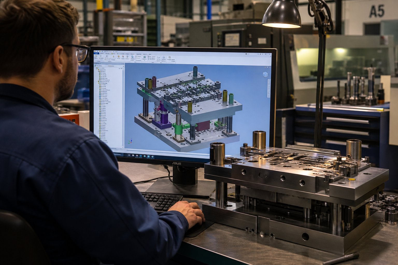
- Detailed die design - Full 3D modeling of every component: die shoes, punches, die blocks, strippers, pilots, springs, and fasteners. Design reviews at this stage confirm that the tooling matches press specifications, material feed systems, and automation requirements.
- CNC machining and assembly - Precision machining of die components from specified tool steels, followed by heat treatment, grinding, EDM, and coating application. Assembly includes fitting all components, verifying alignment, and checking clearances before the die ever sees a press.
- Trial runs and dimensional inspection - The die runs sample parts under production conditions. First-article inspection using CMM or optical measurement verifies that parts meet drawing tolerances. Adjustments happen here - shimming, regrinding, or clearance modification - until parts consistently pass inspection.
- Production approval and handoff - Final documentation package including inspection reports, material certifications, maintenance guidelines, and spare parts recommendations. The die is ready for sustained production.
What should sourcing managers and tooling engineers evaluate when choosing among die manufacturers? Industry experience suggests focusing on four areas: technical capability (press range, material expertise, in-house tooling), simulation and engineering support (DFM feedback, prototyping, CAE analysis), quality systems (ISO 9001 or IATF 16949 certification, inspection equipment, documentation practices), and communication responsiveness throughout the development process.
A metal stamping die manufacturer that controls the entire workflow internally - from feasibility analysis through final inspection - reduces the coordination risk that plagues multi-vendor approaches. For example, YICHEN offers this end-to-end capability including CAE simulation, precision CNC machining, trial runs, and dimensional inspection as an integrated process. For sourcing managers evaluating custom metal stamping dies suppliers, this type of single-source workflow demonstrates what an RFQ-ready process looks like: one point of accountability from concept validation through production approval.
The key questions to ask any prospective die shop during evaluation:
- Do you run forming simulations in-house, or outsource them?
- What inspection equipment verifies first-article parts - CMM, optical, or basic hand tools only?
- How many trial iterations does your average custom die require before production sign-off?
- Who owns the tooling, and what does your maintenance support look like post-delivery?
- Can you provide references from programs with similar volume, material, and complexity?
The answers reveal whether a supplier is a true engineering partner or simply a machine shop that cuts steel to your prints. Custom metal stamping die development demands collaboration - the die manufacturer needs enough process knowledge to push back on designs that won't stamp well, and enough capability to deliver tooling that runs reliably from day one.
Selecting the right die and the right partner gets you into production. Staying in production - maintaining part quality over hundreds of thousands or millions of cycles - depends on what happens after the tooling ships. That's where preventive maintenance separates shops running at peak efficiency from those constantly firefighting quality escapes.
Preventive Maintenance and Die Life Optimization
A perfectly designed, precisely built press die set starts degrading the moment it runs its first stroke. That's not a defect - it's physics. Hardened steel under repeated high-tonnage impact wears, shifts, and fatigues over time. The difference between a die that delivers consistent parts for millions of cycles and one that spirals into chronic quality escapes comes down to how you manage that inevitable wear. Stamping die maintenance isn't glamorous work, but it's the highest-leverage activity on your shop floor for protecting part quality and avoiding unplanned downtime.
Common Die Failure Modes and Root Causes
When parts start showing burrs, dimensional drift, or surface defects, the root cause usually traces back to one of a handful of failure modes. Knowing which one you're dealing with saves hours of guesswork.
Misalignment is the silent killer. Guide pins and bushings wear gradually from repetitive high-pressure cycling, and even a few thousandths of inch drift causes uneven cutting, one-sided burrs, and accelerated punch wear. JVM Manufacturing notes that misalignment creates a domino effect throughout the entire die system - when one station operates slightly off-center, it stresses adjacent stations and compounds wear across the tool. Press gib wear amplifies the problem by introducing ram deflection that the die's internal guides can't compensate for.
Cutting edge deterioration takes multiple forms. Chipping happens when punches encounter excessive shock - common with high-strength materials or when clearance is too tight. Galling occurs when workpiece material transfers and welds to the die surface under pressure, particularly with stainless steel and aluminum. Built-up edge accumulates gradually, changing effective clearance until burr height exceeds spec. Each of these shows up differently in your parts: chipping produces inconsistent edge quality, galling creates scratches and score marks, and built-up edge drives progressive burr growth across a production run.
Timing and feed failures plague progressive dies specifically. Pilot wear, feed-roll-lift timing drift, and strip tracking problems cause the material to arrive at each station slightly off-position. The result is compounding dimensional errors from station to station - a problem unique to any die process that relies on sequential strip advancement. Material feed issues including incorrect pitch, strip camber, and inadequate lifter rail clearance create misfeeds that can crash the die if not caught immediately.
Preventive Maintenance Schedules and Sharpening Intervals
Reactive maintenance - waiting for something to break - carries hidden costs that dwarf the repair itself. MetalForming Magazine distinguishes clearly between repair (restoring something broken) and maintenance (preserving current condition), noting that many organizations don't know their actual maintenance costs because they're really tracking repair costs. The exponential reduction in hidden costs - quality spills, expedited shipments, idle time, debugging - produces the greatest savings when you replace firefighting with effective PM programs.
A strong preventive schedule for punch press dies combines time-based checks with stroke-count triggers. Calendar intervals prevent routine tasks from being skipped during heavy production weeks, while hit-based triggers account for the fact that dies don't all wear at the same rate. A blanking die running abrasive stainless needs sharpening attention far sooner than the same design stamping mild steel.
Sharpening intervals should be established from actual wear data, not arbitrary numbers. A common starting point is reviewing cutting edge condition every 50,000 to 100,000 strokes for standard materials, tightening to 20,000 to 30,000 strokes for high-strength or abrasive stock. But the real trigger is measurable: when burr height exceeds your quality threshold - often 10% of material thickness - it's time to sharpen. Waiting beyond this point doesn't just affect part quality; it removes more material during regrinding and shortens overall die life.
Here's a step-by-step preventive maintenance checklist ordered by inspection frequency, applicable whether you're running a hydraulic press die or a mechanical setup:
- Every shift - Check for visible burrs on sample parts, listen for abnormal noise, verify lubricant delivery, and clear accessible slugs and debris from scrap paths.
- Daily - Inspect pilots, springs, and strip tracking. Review scrap flow for blockages. Compare part dimensions against control limits and log any quality drift.
- Weekly - Examine guide pins and bushings for scoring or unusual wear patterns. Check fastener security on punches and retainers. Verify stripper plate return and spring condition.
- Monthly - Measure cutting edge condition and clearance at critical stations. Inspect die shoes for witness marks or warping. Review sharpening history and plan controlled downtime for service.
- Per stroke-count interval - Perform scheduled sharpening based on documented wear rates. Replace springs before calculated end-of-life. Inspect and service cam surfaces, heel blocks, and high-wear inserts.
- Annually or at major milestones - Conduct full die teardown, metrology review, and comprehensive condition assessment. Update PM documentation and adjust intervals based on accumulated data.
Wear Indicators and When to Replace vs. Repair
Every precision die stamping operation produces wear indicators that signal whether you need routine service, targeted repair, or full replacement. Reading those signals correctly prevents both premature spending and catastrophic failure.
Routine sharpening territory: Gradual burr growth that responds to regrinding. Slight dimensional drift that corrects after sharpening. Edge rounding visible under magnification but without chipping or cracking. These are normal wear patterns - your die is working as designed, just needs its edges refreshed.
Repair territory: Localized chipping or cracking on individual punches or inserts. A single spring that's lost free length. One guide bushing showing scoring while others remain clean. These point to component-level issues that targeted replacement resolves without rebuilding the entire tool.
Replacement territory: Recurring dimensional drift that returns within one production run after sharpening. Repeated alignment loss despite guide component replacement. Chronic galling or defect patterns that suggest a geometry or load issue rather than surface wear. Multiple stations degrading simultaneously. When records show the same problem returning after verified maintenance - not just once, but repeatedly - routine PM has reached its limit.
The economics are straightforward. A typical regrind removes 0.002 to 0.005 inches of material per sharpening cycle. Most punches allow 15 to 30 regrinds before reaching minimum length. Multiply your sharpening interval by the number of available regrinds and you have an estimated total die life for cutting components. When that math says you're within two or three sharpening cycles of end-of-life, start planning replacement components rather than discovering the need during a production crunch.
Track every sharpening date, stroke count at service, and burr measurement at the time of pull. That history turns die maintenance from guesswork into predictable planning - and reveals when repair costs are approaching new-component economics.
Documentation closes the loop. Without records of stroke counts, defect types, maintenance actions, and post-service validation results, every PM decision becomes a guess. With them, you can predict when the next press die needs attention, budget for component replacements before they become emergencies, and identify dies that consume disproportionate maintenance resources - signaling that redesign or replacement may deliver better lifecycle economics than another round of regrinding.
Preventive maintenance keeps your tooling running. But the next evolution - embedding sensors directly into the die to monitor force, temperature, and vibration in real time - is transforming how manufacturers detect degradation before it ever reaches the parts.

Smart Dies and Your Path to Production-Ready Tooling
Scheduled maintenance catches problems on a calendar. But what if the die told you it was wearing - right now, mid-production - before a single bad part reached the end of the line? That's exactly what sensor-equipped metal stamping dies deliver, and the technology is reshaping how manufacturers think about tooling, quality, and uptime.
Sensor-Equipped Dies and Real-Time Monitoring
Imagine force sensors, accelerometers, and temperature probes embedded directly inside your die shoes and punch retainers. Every stroke generates a force signature - a fingerprint of how that cycle performed. When cutting edges dull, peak force drifts upward. When alignment shifts, lateral acceleration spikes. When friction increases between punch and die at higher stroke speeds, temperature readings climb in specific stations.
Research from the Technical University of Darmstadt demonstrates this in practice: by equipping progressive dies with multiple force and acceleration sensors, stroke-rate-dependent anomalies can be detected early and countermeasures derived proactively - before product quality degrades. Their work showed that vibrations and friction patterns correlate directly with measurable part defects like bending angle deviation, and that sensor data combined with machine learning models can pinpoint which specific die station is causing the problem.
This isn't theoretical. Closed-loop feedback architectures already enable real-time parameter corrections within the same production cycle. When a force signature deviates beyond statistical control limits, the system can automatically adjust blankholder pressure, flag the metal stamped part for inspection, or trigger maintenance alerts - all without stopping the press. For sheet metal stamping operations running 500+ strokes per minute, even a 0.1% sampling rate provides enough data density to detect process drift within seconds.
The payoff extends beyond immediate defect prevention. Over time, sensor data feeds back into die design optimization. Engineers can see exactly where stress concentrations develop, which coatings degrade fastest, and how material variation affects forming outcomes across millions of cycles. Future sheet metal stamping dies get designed with this production intelligence built in - shorter development cycles, fewer trial iterations, and tooling that performs better under real-world conditions from day one.
Moving From Research to Your Next Stamping Die Project
You've covered significant ground: die type selection based on volume and geometry, material and construction choices that determine longevity, design parameters that drive part quality, maintenance strategies that protect your investment, and now real-time monitoring that catches problems before they propagate. These aren't isolated topics - they're sequential decisions that build on each other.
Your next step depends on where you are right now:
- Specifying new tooling - Start with your part geometry, annual volume, and material. Use the die type framework to narrow your options, then engage a manufacturer early enough for feasibility assessment and CAE simulation before committing to detailed design. This front-end investment in metal parts stamping validation prevents expensive corrections in hardened steel later.
- Optimizing existing dies - Review your maintenance data for patterns. If specific stations consume disproportionate regrinding cycles or produce recurring defects, the root cause likely sits in clearance, alignment, or material selection - not just normal wear. Consider sensor integration on your highest-volume tools to shift from scheduled maintenance to condition-based intervention.
- Evaluating die suppliers - Look for end-to-end capability: in-house simulation, precision machining, controlled trial runs, and dimensional inspection under one roof. Fragmented supply chains introduce coordination risk at every handoff. A manufacturer like YICHEN that controls the full workflow - from feasibility assessment and CAE simulation through CNC machining, trial production, and final inspection - gives sourcing managers and tooling engineers a single point of accountability for custom stamping parts and metal stamping components.
The tooling decisions you make today show up in every stamped metal part that rolls off the press tomorrow. Whether you're launching a new program or squeezing more life from existing dies, the principles remain the same: match die type to application, specify materials for your actual production demands, validate design through simulation, maintain based on data rather than habit, and partner with manufacturers who treat your tooling as an engineering problem - not just a machining job.
Every metal stamping die is a bet on production outcomes. Make it an informed one.
Frequently Asked Questions About Stamping Press Dies
1. What is a stamping press die and how does it work?
A stamping press die is precision tooling made from hardened tool steel or carbide that transforms flat sheet metal into finished parts. It consists of matched upper and lower halves mounted inside a press. When the press cycles, the upper half descends into the lower half, and the metal between them is cut, bent, drawn, or formed into a specific shape. The press supplies the force while the die defines the part geometry, controlling every quality attribute including dimensional accuracy, edge condition, and surface finish.
2. What are the main types of stamping dies and when should each be used?
The four main types are single-station dies, compound dies, progressive dies, and transfer dies. Single-station dies perform one operation per stroke and suit low-to-medium volumes under 10,000 parts annually. Compound dies handle multiple cutting operations in one stroke for moderate volumes. Progressive dies advance strip material through multiple stations for high-volume complex parts exceeding 100,000 annually. Transfer dies move individual blanks between stations and work best for large or deep-drawn parts that cannot remain on a carrier strip. Selection depends on balancing volume, part complexity, tolerance needs, and upfront tooling cost.
3. How does punch-to-die clearance affect stamped part quality?
Punch-to-die clearance, the gap between cutting edges expressed as a percentage of material thickness per side, directly determines edge quality, burr formation, and die wear rate. Correct clearance allows fracture lines from the punch and die edges to meet cleanly, producing smooth cuts with minimal burr. Too little clearance generates excessive force, heat, and accelerated punch wear. Too much clearance causes material to roll and tear, leaving heavy burrs. The optimal value varies by material: low-carbon steel typically uses around 10% per side, while high-strength steels need wider clearances and aluminum often requires tighter values.
4. How often should stamping dies be maintained and sharpened?
Preventive maintenance frequency depends on material abrasiveness, production volume, and observed wear patterns. A common starting point is reviewing cutting edges every 50,000 to 100,000 strokes for standard materials, tightening to 20,000 to 30,000 strokes for high-strength or abrasive stock. The measurable trigger for sharpening is when burr height exceeds 10% of material thickness. Beyond sharpening, effective PM programs include daily pilot and spring inspections, weekly guide pin checks, monthly clearance measurements, and annual full teardowns. Tracking stroke counts and burr data at each service turns maintenance into predictable planning rather than reactive firefighting.
5. What should I look for when choosing a stamping die manufacturer?
Evaluate four core areas: technical capability (press range, material expertise, in-house tooling), simulation support (CAE forming analysis, DFM feedback), quality systems (ISO or IATF certification, CMM inspection), and communication responsiveness. Prioritize manufacturers that control the full workflow internally, from feasibility assessment and CAE simulation through CNC machining, trial runs, and dimensional inspection. This single-source approach, offered by suppliers like YICHEN, reduces coordination risk at every handoff and provides one point of accountability from concept validation through production approval. Ask how many trial iterations their average die requires and whether they run forming simulations in-house.


