
Stamping Die Tooling: What It Really Costs and Why It Fails
What Stamping Die Tooling Really Means and Why It Matters
If you have ever wondered what is metal stamping, the answer starts with one thing: the tooling inside the press. Every bracket, clip, terminal, and panel that rolls off a stamping line owes its shape, accuracy, and consistency to a precisely engineered set of tools working in concert at hundreds-sometimes thousands-of strokes per hour. Without the right tooling, even the most powerful press is just an expensive machine slamming steel against steel.
So what are dies, and how do they fit into the bigger picture? Here is a clean stamping definition you can take straight to the shop floor:
Stamping die tooling is the complete engineered tool set-including punches, die blocks, stripper plates, and guide systems-installed inside a stamping press to cut, bend, draw, and form sheet metal into finished parts at production speed.
That single sentence captures the scope, but the details matter. A stamping die is not a single piece of steel. It is an assembly of interdependent components, each with a specific mechanical job. Understanding the distinction between those components is the first step toward controlling quality, cost, and uptime.
Defining Stamping Die Tooling in Modern Manufacturing
Three terms come up constantly-and they are often used interchangeably, which leads to confusion. Here is how they actually differ:
- Die: The female half of the tool set. It contains the shaped cavity or cutting edge that the material is pressed into or sheared against. Think of it as the mold side of the equation.
- Punch: The male counterpart. It delivers forming or cutting force by pushing the sheet metal into or through the die cavity. The punch and die must match with extremely tight clearances-often within thousandths of an inch.
- Die set (tooling package): The full assembly that includes the punch, die block, stripper plate, guide pins, bushings, backing plates, and all supporting hardware mounted on upper and lower die shoes. This is what gets bolted into the press.
When someone asks "what is dies in manufacturing," they are really asking about this entire system. The die block alone does nothing useful without the punch driving material into it, the stripper plate holding the stock flat, and the guide system keeping everything aligned stroke after stroke. High-quality tooling enables manufacturers to hold tolerances as tight as 0.0002 inches across millions of cycles-a level of repeatability that no other forming method can match at comparable speed and cost.
Why Die Tooling Is the Foundation of Every Stamped Part
Imagine running a stamping press at 400 strokes per minute. Every single hit must land in exactly the same position, apply exactly the same force, and produce exactly the same part geometry. The tooling is what makes that possible. It is the single largest determinant of part quality, dimensional consistency, and per-piece cost in high-volume metal stamping.
Poor tooling design or craftsmanship introduces a cascade of problems: inconsistent parts, higher scrap rates, unplanned press stoppages, and expensive secondary operations like deburring that should never have been necessary in the first place. A well-built stamping die, on the other hand, delivers clean cuts, tight tolerances, and smooth part flow-often eliminating the need for downstream machining entirely.
That relationship between tooling quality and production economics is exactly what this article unpacks. In the sections ahead, you will find a detailed comparison of die types and when each one makes financial sense, a component-by-component breakdown of how a stamping die actually works, guidance on tool steel selection and surface treatments, a look at modern simulation and strip layout optimization, a troubleshooting reference for the most common failure modes, a realistic framework for understanding tooling costs, and practical advice on evaluating suppliers. Each section is built to give you the engineering depth and decision-making clarity that surface-level overviews skip entirely.
The logical starting point? Understanding which type of die belongs in your press in the first place-because that single decision shapes every cost and capability that follows.
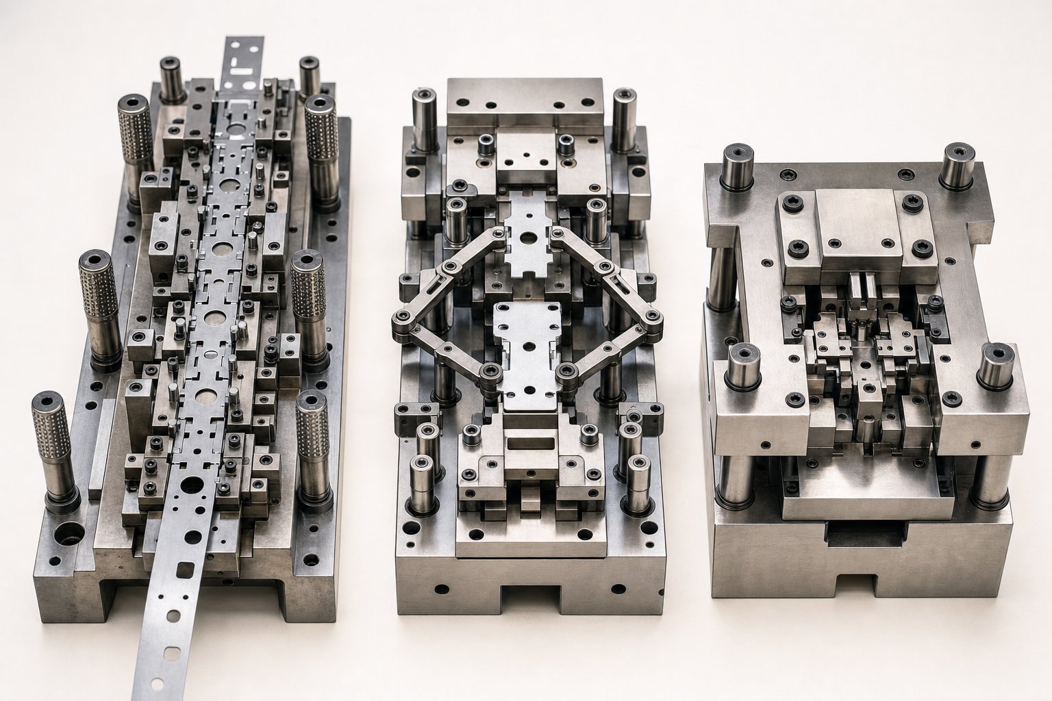
Types of Stamping Dies and How to Choose the Right One
Choosing the wrong die type is one of the most expensive mistakes in metal stamping. It locks you into a cost structure, a cycle rate, and a set of geometric limitations that follow the project for its entire production life. The challenge is that the four major types of stamping dies-progressive, transfer, compound, and combination-overlap enough to create real confusion, yet differ enough that picking incorrectly can double your tooling spend or slash your throughput.
So how do you decide? You match the die process to three variables: part geometry, annual volume, and tolerance requirements. Get those three right, and every downstream decision-material grade, maintenance schedule, press selection-falls into place more naturally.
Progressive Dies vs. Transfer Dies vs. Compound Dies
Each of the major types of dies operates on a fundamentally different principle, and that principle dictates what it can and cannot do efficiently.
Progressive dies feed a continuous metal strip through a series of stations, each performing a different operation-piercing, notching, bending, forming-until the finished part is cut free at the final station. The strip acts as its own conveyor, which eliminates part handling between operations and enables stroke rates that routinely exceed 200 hits per minute for small parts. This makes progressive tooling the go-to choice for high-volume runs of small to mid-size components like electrical terminals, brackets, and clips.
Transfer dies take a different approach. Individual blanks are separated from the strip early and then mechanically transferred from station to station by a dedicated transport system-typically finger mechanisms or walking beams. This is essential for parts that are too large, too deep-drawn, or too geometrically complex to remain attached to a carrier strip. Transfer stamping is common in appliance housings, automotive body panels, and structural components where three-dimensional forming depth makes strip-based feeding impractical.
Compound dies perform multiple cutting operations-blanking and piercing, for example-in a single press stroke. Because every feature is produced simultaneously, alignment between operations is nearly perfect. The tradeoff is speed: compound dies typically run slower than progressive tooling and are best suited for flat or near-flat parts where dimensional precision matters more than cycle rate. Washers, gaskets, and flat electrical contacts are classic compound-die applications.
Combination dies blend cutting and forming operations into one stroke-think blanking and bending happening simultaneously. They occupy a niche between compound and progressive tooling, offering moderate complexity at moderate volume with less tooling investment than a full progressive setup.
| Die Type | Operating Principle | Best-Fit Part Complexity | Ideal Volume Range | Relative Cost | Cycle Speed |
|---|---|---|---|---|---|
| Progressive | Strip advances through multiple stations; each station performs one operation | Small to mid-size parts with multiple features (bends, holes, forms) | 100,000+ parts/year | High | Fast (200-1,500+ SPM) |
| Transfer | Individual blanks mechanically moved between separate stations | Large, deep-drawn, or 3D-complex parts | 25,000-500,000+ parts/year | High to very high | Moderate (15-80 SPM) |
| Compound | Multiple cutting operations in a single stroke on one station | Flat or near-flat parts needing tight feature-to-feature accuracy | 10,000-250,000 parts/year | Moderate | Moderate (40-200 SPM) |
| Combination | Cutting and forming operations combined in one stroke | Moderately complex parts with both cut and formed features | 10,000-150,000 parts/year | Moderate | Moderate (30-150 SPM) |
Matching Die Type to Production Volume and Part Geometry
Volume thresholds are where theory meets budgeting reality. A single-station die might cost a fraction of a progressive setup, but its per-part cost stays flat regardless of volume. A progressive die, by contrast, demands a steep upfront investment that only pays off once production volume is high enough to amortize the tooling across enough parts. In practice, that crossover point typically sits somewhere between 50,000 and 100,000 annual parts-though part complexity and cycle time push that number up or down.
When does transfer stamping make more sense than progressive? The deciding factor is usually part geometry, not volume alone. If the part requires deep draws, large panel areas, or forming operations that would distort or break a carrier strip, transfer tooling becomes the only viable path. You will also see transfer dies specified when finished parts need to be rotated or repositioned between stations-something a progressive strip simply cannot accommodate.
For lower volumes or prototype runs, compound or combination metal stamping dies often represent the smartest investment. They keep tooling costs manageable while still delivering the dimensional consistency that hand-fed single-station setups struggle to maintain.
Understanding Class A, B, and C Tooling Classifications
Beyond die type, tooling class determines how long your stamping dies will last-and how much you should expect to spend maintaining them. The classification system ties directly to expected die life measured in total hits:
- Class A tooling: Built for the long haul. These dies use premium tool steels, carbide inserts at high-wear stations, and hardened components throughout. Expected die life often exceeds 1,000,000 hits, making Class A the standard for automotive production and other high-volume programs where uninterrupted uptime is critical.
- Class B tooling: A practical middle ground. Constructed with quality tool steels but fewer premium inserts, Class B dies typically deliver 250,000 to 1,000,000 hits. They suit mid-volume production where tooling cost needs to stay proportional to total order value.
- Class C tooling: Designed for short runs, prototypes, or bridge production. Materials and construction are simplified to minimize upfront cost, with expected die life under 250,000 hits. Class C is the right call when you need parts fast and the total lifetime quantity does not justify a heavier investment.
Selecting the right class is not about choosing the "best" option-it is about matching tooling investment to production reality. Over-specifying a Class A die for a 50,000-part lifetime run wastes capital. Under-specifying Class C tooling for a million-part program creates a cycle of premature wear, regrinding, and eventual rebuild that costs far more in the long run.
Each of these die types and classifications, though, is only as good as the individual components inside the tool. The punch, die block, stripper, and guide system each play a distinct mechanical role-and when any one of them starts to wear, the effects ripple through every part that comes off the press.
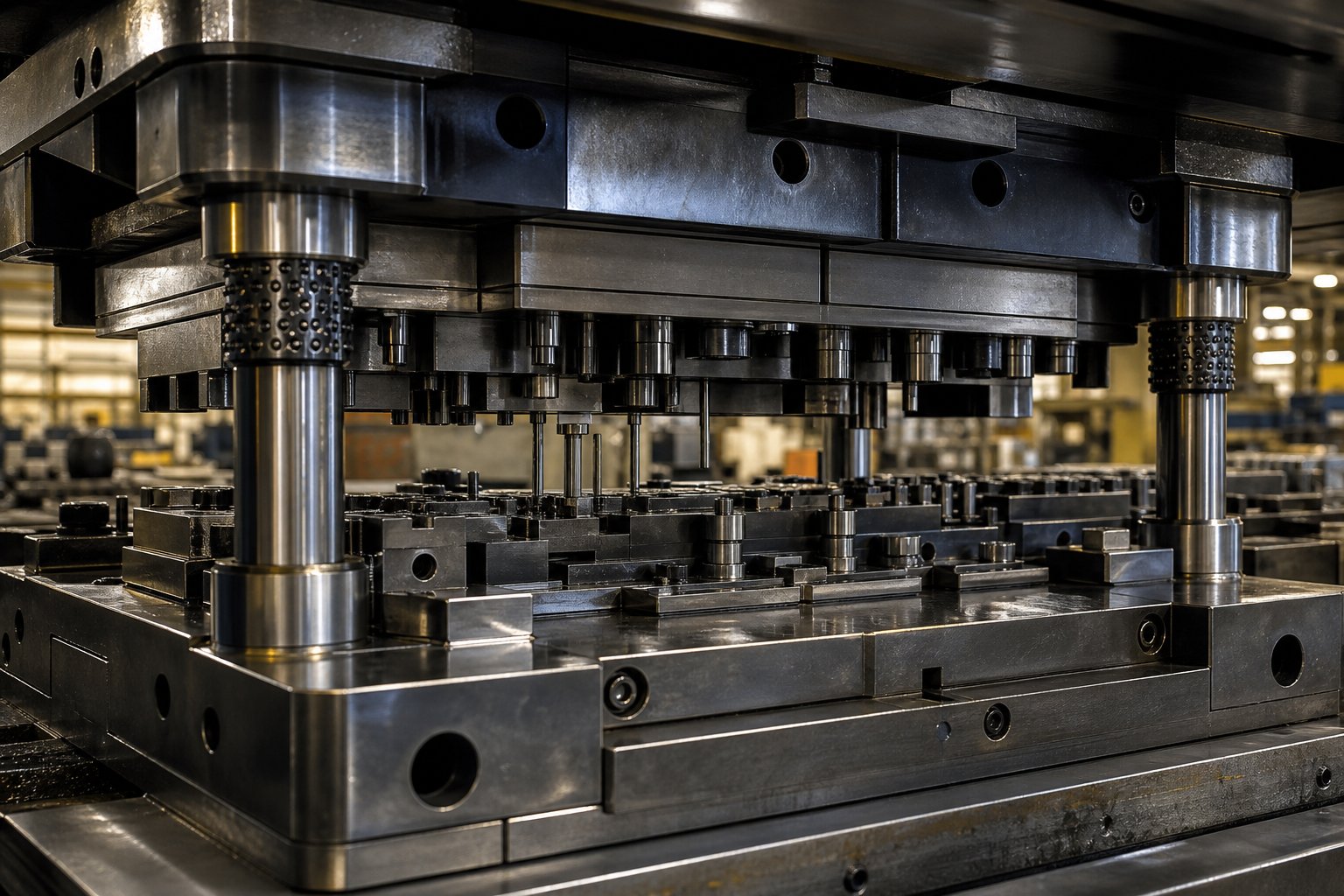
Critical Components Inside a Stamping Die Explained
A stamping die looks like a solid block of steel from the outside, but crack it open and you will find a carefully orchestrated assembly of individual components-each one engineered to perform a specific mechanical function during every press stroke. Understanding these stamping die components is not just academic. It is the difference between diagnosing a problem in minutes and spending hours chasing symptoms while scrap piles up at the end of the line.
Here is a quick functional overview of the core metal stamping components before we dig into how they actually work together:
- Punch: Delivers cutting or forming force by driving into the workpiece material.
- Die block: Provides the mating cavity or cutting edge that shapes or shears the material against the punch.
- Stripper plate: Holds the strip flat against the die surface and strips it off the punch during the return stroke.
- Guide pins and bushings: Maintain precise alignment between the upper and lower die halves throughout every stroke.
- Pilots: Register the strip to an exact position at each station, ensuring every feature lands where it should.
- Backing plates: Distribute punch loads across the die shoe to prevent localized damage and deformation.
Each of these parts has a clearly defined job. The real complexity-and the real source of quality problems-lies in how they interact under load, at speed, stroke after stroke.
How Punch, Die Block, and Stripper Plate Work Together
Imagine a single cutting stroke in slow motion. The press ram descends, bringing the upper die shoe downward. The stripper plate, loaded by springs, contacts the sheet metal strip first and presses it firmly against the lower die surface. This is critical-if the strip is not held flat and secure before the punch contacts the material, the cut will distort, the part will shift, and burrs will form on the wrong side of the edge.
A fraction of a second later, the punch penetrates the strip. In a punching stamping operation, the punch shears through the material by driving it into the die block opening below. The clearance between the punch and die block-typically expressed as a percentage of material thickness-determines the quality of the cut edge. Too tight, and the tool wears prematurely. Too loose, and you get excessive burring and rollover. For mild steel, clearances often fall in the range of 5-10% of material thickness per side, though harder materials like stainless steel demand tighter values.
On the return stroke, the spring-loaded stripper plate performs its second function: it holds the strip down while the punch withdraws. Without it, the material would cling to the punch body-especially during piercing, where the metal collapses tightly around the punch shank. The stripper literally strips the material free, allowing the strip to advance to the next station cleanly.
The die block, meanwhile, is not just a passive opening. Its cutting edges must be ground to precise geometry and hardness to produce clean shear surfaces. In forming stations, the die block serves as the cavity that defines the final shape of the metal stamped part, making its surface finish and dimensional accuracy just as important as the punch geometry above it.
Guide Systems, Pilots, and Alignment Precision
Punches and die blocks can be perfect on their own, yet still produce bad parts if alignment drifts even a few thousandths of an inch. That is the job of the guide system-and it is arguably the most underappreciated element in the entire tool.
Guide pins and bushings are the primary alignment mechanism. Hardened steel pins mounted on one die half slide into precision-bored bushings on the opposite half, constraining the upper and lower shoes to travel on a single, repeatable path. In high-speed progressive dies running at hundreds of strokes per minute, the guide system absorbs lateral forces and thermal growth while keeping alignment within microns. Ball-bearing guide assemblies are common in precision applications because they reduce friction and resist wear better than plain bushings.
Pilots handle a different alignment challenge: strip registration. As the metal strip advances from station to station in a progressive die, pilots-small, tapered pins mounted on the upper die-enter pre-pierced holes in the strip and pull it into exact position before any cutting or forming occurs. The taper allows the strip to self-center, correcting minor feed errors before the press reaches bottom dead center. Without accurate piloting, hole-to-hole spacing, bend locations, and feature positions drift from station to station, and the cumulative error can push stamped metal parts out of tolerance well before any cutting edge shows visible wear.
Backing plates play a quieter but essential structural role. Positioned between the punch retainers and the die shoe, these hardened plates spread the concentrated force of each punch impact across a wider area. Skip the backing plate, and individual punches will gradually peen the die shoe surface-creating small indentations that shift punch position over time and quietly degrade part accuracy.
Recognizing Component Wear Before It Affects Part Quality
Every component in a stamping die is a wear item. The question is never whether it will wear, but how quickly you can detect that wear before it shows up in your parts.
Punch wear is the most visible. A sharp cutting punch produces a clean shear zone with a narrow burr. As the cutting edge dulls, burr height increases, the shear band narrows, and cutting force rises-sometimes noticeably enough for press operators to hear the difference. The decision between regrinding and full replacement depends on how much material has already been removed from the punch length. Most punches can be reground several times before they reach a minimum length threshold, below which the punch no longer engages the die block deeply enough to complete a clean cut.
Die block edge wear follows a similar pattern but is harder to see without removing the die from the press. Experienced toolmakers look for secondary indicators: increasing burr on the part, slug sticking in the die opening, or a gradual shift in blank dimensions that signals the cutting profile has grown slightly from edge erosion.
Guide pin and bushing wear manifests differently-and more insidiously. Rather than a sudden defect, you will notice a slow dimensional drift across multiple part features. Hole positions shift slightly, bend lines wander, and feature-to-feature dimensions start trending toward the edge of the tolerance band. If your CMM data shows a progressive trend rather than random scatter, worn guide components are a prime suspect.
Pilot wear or damage creates strip misregistration that looks like random variation but actually follows the feed cycle. Parts may alternate between good and marginal as the strip slightly over- or under-advances at specific stations. Checking pilot diameters and taper condition during scheduled maintenance catches this before scrap rates spike.
The core takeaway is straightforward: component precision and final part tolerance are directly linked. A stamping die does not gradually decline in vague, hard-to-trace ways. Each component wears in a characteristic pattern that produces a specific, identifiable signature in the finished part. Learning to read those signatures-through dimensional trending, visual inspection, and force monitoring-is what separates reactive firefighting from proactive die maintenance.
Of course, how fast these components wear depends heavily on what they are made from. The choice of tool steel grade, hardness level, and surface treatment for each component is one of the least discussed-and most consequential-decisions in the entire tooling process.
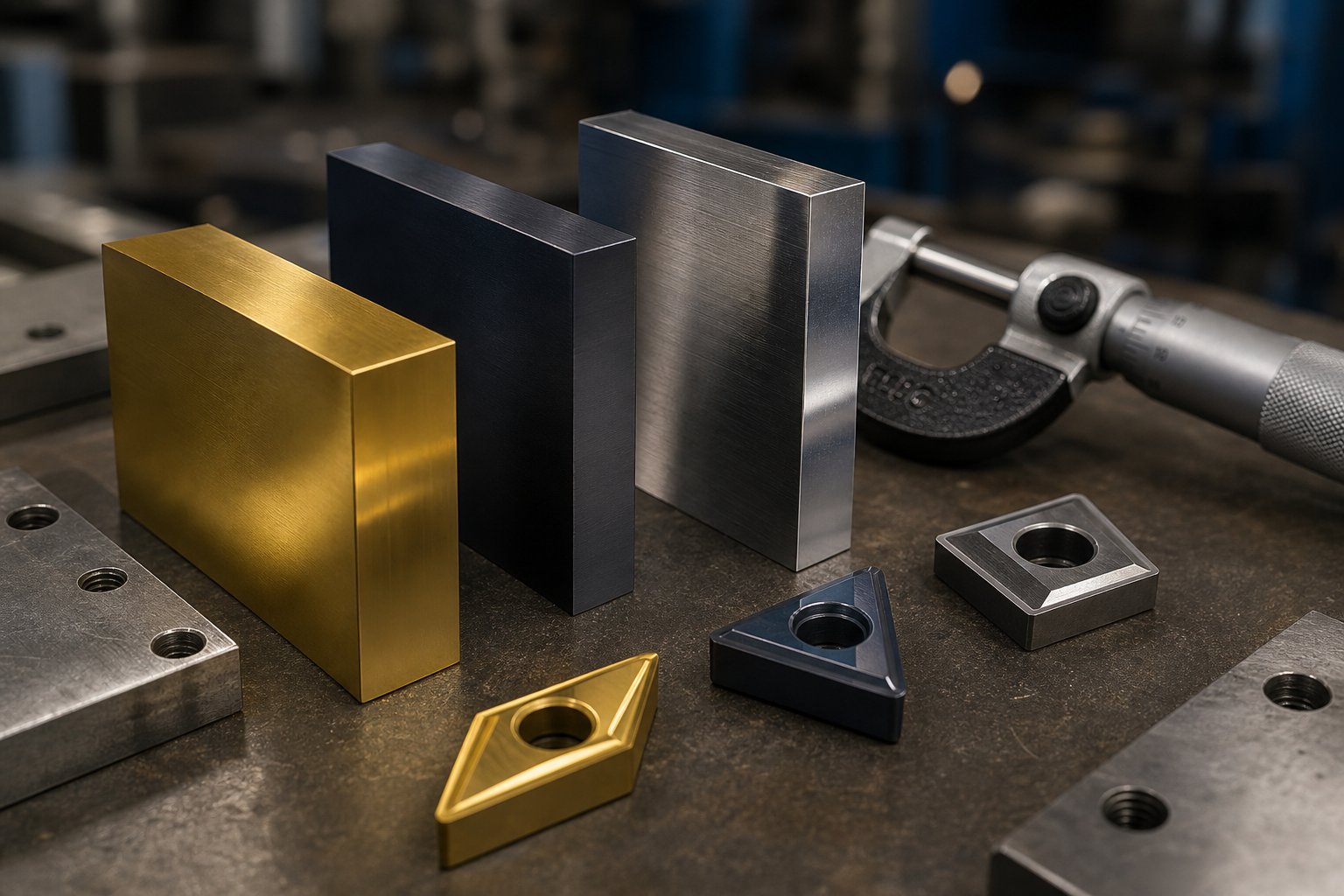
Stamping Die Material Selection and Surface Treatment Guide
The tool steel inside your stamping die determines how many parts you can run before regrinding, how tight your tolerances hold over long production campaigns, and whether your die fails gracefully or catastrophically. Yet material selection is one of the most overlooked decisions in the tooling process-often left to default choices or supplier preferences rather than deliberate engineering analysis.
Different stamping die steel grades sit at different points on a hardness-versus-toughness spectrum, and picking the wrong spot on that spectrum for your application is a fast track to premature tool failure. Here is how the most common grades compare and when each one earns its place in a die build.
Tool Steel Grades for Stamping Dies and Their Performance Tradeoffs
Five tool steel grades cover the vast majority of steel stamping dies in production today. Each belongs to a different metallurgical family, and those family traits dictate performance:
- D2 (high-carbon, high-chromium): The workhorse for long-run blanking and piercing. D2's high chromium content forms hard carbide particles that deliver exceptional abrasion resistance. After hardening and tempering, D2 reaches 62-64 HRC-hard enough to hold a sharp cutting edge across hundreds of thousands of hits. The tradeoff is brittleness under impact; D2 is not the right choice for heavy forming or operations involving shock loads.
- A2 (air-hardening): With 5% chromium and excellent dimensional stability during heat treatment, A2 achieves 63-65 HRC while offering better toughness than D2. It is commonly used for blanking punches, forming punches, and die trimming applications where moderate wear resistance meets moderate impact resistance. A2 is a strong all-around choice for mid-volume stamping die steel builds.
- S7 (shock-resistant): When your die stations involve heavy drawing, deep forming, or repeated mechanical shock, S7 steps in. It hardens to 60-62 HRC but prioritizes impact toughness over abrasion resistance. Think of S7 as the grade that bends before it breaks-ideal for components like draw punches and forming inserts that absorb significant dynamic loads every stroke.
- M2 (high-speed steel): Designed to retain hardness at elevated temperatures, M2 reaches approximately 62-64 HRC and excels in high-stroke-rate applications where friction-generated heat would soften conventional cold-work steels. You will see M2 in cutting punches running at 600+ strokes per minute, where thermal stability directly translates to edge life.
- O1 (oil-hardening): The most economical option, O1 is relatively easy to machine and achieves 57-62 HRC after tempering. It offers a reasonable balance of toughness and wear resistance for short-run production, prototype tooling, and applications where the total hit count does not justify premium steel grades.
The underlying tradeoff is always the same: harder steels resist abrasive wear longer but are more prone to chipping or cracking under impact. Tougher steels absorb shock better but dull faster. Experienced toolmakers mix grades within a single die-using D2 or carbide at high-wear cutting stations and S7 at forming stations where impact resistance matters more than edge retention.
Speaking of carbide, tungsten carbide inserts deserve their own mention. For the highest-wear stations in progressive dies-especially those running abrasive materials like stamped steel with high silicon content or stainless alloys-carbide inserts can outlast even D2 by a factor of five to ten. They are significantly more expensive and more brittle, so they are typically reserved for specific stations rather than used throughout the entire die.
Heat Treatment and Surface Coatings That Extend Die Life
Choosing the right steel grade is only half the equation. How that steel is heat-treated and what coatings are applied to its working surfaces can double or even multiply die life dramatically.
Heat treatment establishes the baseline hardness and toughness of each component. Through-hardening-heating the entire part above its critical temperature and quenching-is standard for cold-work steels like D2 and A2. Case-hardening, by contrast, creates a hard outer shell while maintaining a tough core, which is useful for components that need surface wear resistance but must absorb impact without fracturing. Vacuum heat treatment is strongly recommended regardless of the method; as industry experts note, oxidation caused by non-vacuum processes inhibits coating adhesion and can compromise surface integrity before the die ever runs its first part.
Surface coatings add a secondary layer of protection that dramatically reduces friction and adhesive wear. The most common options include:
- Titanium nitride (TiN): A PVD coating with a hardness around 2,400 HV. TiN provides good general-purpose protection against abrasive and adhesive wear and is widely used on cutting punches. Its gold color makes coating coverage easy to verify visually.
- Titanium carbonitride (TiCN): A step up from TiN at approximately 3,200 HV, TiCN is applied as a multilayer coating and is well-suited for closely toleranced stamping applications where both hardness and dimensional control matter.
- Chromium nitride (CrN): At 1,800 HV it is softer than TiN, but its lower internal stress allows thicker coatings. CrN works well for forming operations where a low coefficient of friction matters more than extreme hardness.
- Nitriding: A thermochemical diffusion process rather than a deposited coating. Nitriding hardens the surface layer of the steel itself, typically to 65-70 HRC equivalent, without adding a discrete coating layer. This makes it useful for large die components where coating thickness tolerances are a concern.
- Chrome plating: An older but still relevant option for improving release properties on draw dies and reducing material pickup during forming operations.
The performance gap between coated and uncoated tooling is not marginal-it can be transformative. One documented case involving a compound punch running 1074 spring steel showed production jumping from 10,000 parts uncoated to 100,000 parts with an AlTiN coating, and up to 250,000 parts when a dry lubricant film was added on top of the AlTiN layer. Those numbers illustrate why coating selection deserves the same engineering attention as base steel grade selection.
One important caveat: not every coating process works with every steel. CVD coatings, deposited at roughly 1,900 degrees F, anneal the tool substrate during application. Steels like A2 and S7 should not be CVD-coated for applications involving impact loads, because the high process temperature degrades their microstructure and reduces impact strength. PVD processes, operating below 900 degrees F, avoid this issue entirely-making PVD the safer default for most stamping tooling unless specific application demands justify CVD or TRD alternatives.
Matching Die Material to Workpiece Material
Here is a reality that trips up a lot of first-time tooling buyers: the material you are stamping dictates the material your die needs to be made from. A die built for carbon steel stamping will not survive a long run of stainless steel without significant modifications, and tooling designed for steel sheet stamping may be over-engineered-and over-priced-for an aluminum stamping process.
Why? Harder workpiece materials generate higher cutting and forming forces, accelerate abrasive wear on die surfaces, and require tighter punch-to-die clearances to achieve clean edges. Softer materials like aluminum and copper produce less tool wear but introduce different challenges-galling, material pickup, and a tendency to tear rather than shear cleanly if clearances are not reduced accordingly.
| Workpiece Material | Recommended Die Steel Grades | Clearance Guideline (% of Thickness per Side) | Relative Expected Tool Life |
|---|---|---|---|
| Mild / Low-Carbon Steel | D2, A2; carbide inserts for high-volume | 5-10% | Baseline (1x) |
| Stainless Steel (300 series) | D2, M2, or carbide; TRD/PVD coatings strongly recommended | 3-6% | 0.4x - 0.6x baseline |
| High-Strength Steel (HSLA, AHSS) | Carbide, D2 with TiCN or AlTiN coating | 4-8% | 0.3x - 0.5x baseline |
| Aluminum Alloys | A2, D2; CrN or DLC coatings to prevent galling | 3-5% | 1.5x - 2.5x baseline |
| Copper / Brass Alloys | A2, O1 for short runs; D2 for longer campaigns | 3-6% | 1.5x - 2x baseline |
Notice the pattern: stainless and high-strength steels slash expected tool life by half or more compared to mild carbon steel stamping, while softer nonferrous materials extend it significantly. This is precisely why tooling quotes vary so much depending on the workpiece material specified on the part drawing. A die quoted for aluminum may use A2 steel with a CrN coating. The same part geometry in 304 stainless might require D2 with carbide inserts and TRD vanadium carbide coating-doubling or tripling the tooling investment but delivering the hit count needed to justify the build.
Clearance adjustments matter just as much. Stainless steel's work-hardening tendency means that excessive clearance does not just create poor edge quality-it accelerates punch wear as the material resists shearing and instead deforms around the cutting edge. Aluminum, on the other hand, demands tighter clearances to avoid the tearing and excessive burring that result from the material's ductility and tendency to flow rather than fracture cleanly.
Getting the die material, heat treatment, coating, and clearance aligned to your specific workpiece material is what separates tooling that lasts from tooling that limps through a production run. But even a perfectly specified die still needs to be designed correctly-and that is where modern simulation and strip layout optimization have fundamentally changed how toolmakers turn a part drawing into a production-ready tool.
Stamping Die Design, Simulation, and Strip Layout Optimization
Perfect material selection and surface treatment mean nothing if the die geometry itself is flawed. A punch made from premium D2 with a TiCN coating will still produce wrinkled, cracked, or out-of-spec parts if the draw bead placement is wrong, the blank holder pressure is miscalculated, or the progression layout wastes 30% of the strip in scrap. That is why stamping die design has shifted so heavily toward digital simulation over the past two decades-catching these problems in software is orders of magnitude cheaper than discovering them during tryout on the press floor.
How Stamping Simulation Reduces Tryout Iterations and Cost
Computer-Aided Engineering (CAE) simulation lets engineers run the entire stamping process virtually-from blank positioning through final part geometry-before a single block of tool steel gets machined. The software models material flow step by step, predicting exactly where problems will appear.
What does simulation actually catch? The critical failure modes that would otherwise surface only during physical tryout:
- Thinning and tearing: The simulation maps material thickness across the entire part, flagging zones where the sheet metal stretches beyond safe limits. Engineers adjust draw radii, add draw beads, or modify blank shape to redistribute material flow before cutting steel.
- Wrinkling: Insufficient blank holder pressure or improper material flow paths cause compression wrinkles in flanges and sidewalls. Simulation identifies these zones and allows iterative adjustment of blank holder forces and bead geometry.
- Springback: After forming forces release, the part rebounds elastically-sometimes enough to push dimensions out of tolerance. Advanced FEA methods account for material anisotropy, the Bauschinger effect, and residual stresses to predict springback magnitude, enabling engineers to apply compensation strategies like over-bending or modified tool geometry before the die is built.
- Force analysis: Calculating total tonnage requirements ensures the die is matched to the right press and that tooling components are sized to handle actual forming loads without premature failure.
The practical payoff is significant. Traditional metal stamping design workflows often required three to five-or more-physical tryout iterations to achieve acceptable parts. Each iteration means disassembling the die, machining corrections, reassembling, and running again. Simulation-driven stamping design compresses that cycle dramatically, often cutting tryout iterations in half and slashing weeks from the development timeline.
Strip Layout Optimization for Maximum Material Utilization
In progressive die design, the strip layout is where cost engineering happens. Every millimeter of wasted material between parts, every oversized carrier bridge, and every suboptimal nesting angle translates into tonnage of scrap metal over a production run of millions of strokes. Traditional die designs routinely produce scrap rates of 25% to 40%, while optimized layouts can push that figure below 15%.
Engineers control scrap through several interconnected decisions in the stamping die design phase:
- Nesting strategies: Positioning parts as closely as possible-or interlocking them based on geometry-directly maximizes material utilization from the coil. Even minor adjustments to a part's orientation relative to the strip axis can yield 10% to 20% savings in raw material cost.
- Pitch and bandwidth control: The progression distance (pitch) and strip width must be calculated to sub-millimeter accuracy. Unnecessary gaps between stations waste material on every single stroke.
- Carrier bridge design: The bridges connecting each part to the strip need to be narrow enough to minimize scrap yet wide enough to maintain structural integrity during feeding. Get this wrong and the strip buckles or tears mid-run.
- Common-cut techniques: In dies producing multiple parts per stroke, shared cutting lines between adjacent blanks can eliminate inter-part scrap entirely.
Strip layout is not a cosmetic exercise-it is one of the most powerful levers engineers have for reducing per-part cost. A 10% improvement in material utilization on a million-part annual run of 1mm stainless steel adds up to thousands of dollars in savings, all captured before the first production hit.
From Feasibility Study to CNC-Machined Die Components
Metal stamping die design follows a structured workflow that transforms a part drawing into a production-ready tool. Each stage builds on the previous one, and skipping steps-or rushing through them-is where costly mistakes originate.
- Part feasibility assessment: Engineers evaluate the part geometry, material, tolerances, and volume requirements to determine whether stamping is viable, which die type is appropriate, and where potential forming challenges exist.
- 2D strip layout: The progression sequence, station assignments, and material utilization strategy are mapped in a flat layout, defining what happens at each die station and how the strip moves through the tool.
- 3D die modeling: The full die assembly-punches, die blocks, strippers, guide systems, and all supporting hardware-is designed in CAD with precise fits, clearances, and fastener locations.
- Simulation validation: CAE software runs the forming process virtually, verifying material flow, checking for thinning and wrinkling, predicting springback, and confirming tonnage requirements. The 3D model is refined iteratively until simulation results meet acceptance criteria.
- CNC machining of die components: Validated designs move to precision wire EDM, CNC milling, and grinding operations to produce each component to specification.
- Assembly and trial runs: The completed die is assembled, installed in a tryout press, and run through progressively refined iterations until sample parts meet dimensional and quality targets.
This end-to-end process demands tight coordination between design engineers, simulation analysts, CNC machinists, and tryout technicians. Full-service toolmakers who keep every stage under one roof-feasibility through final inspection-eliminate the handoff delays and miscommunication that plague multi-vendor workflows. YICHEN, for example, executes this complete workflow internally, from initial CAE simulation and die design through precision CNC machining, trial runs, and part inspection, giving manufacturers a single point of accountability from concept to production-ready tooling.
A well-designed, simulation-validated die dramatically reduces surprises at tryout. But it does not eliminate them entirely. Material variability, press deflection, and real-world friction conditions still introduce issues that only surface when steel hits steel-which is exactly why understanding the most common failure modes, their root causes, and their corrective actions is essential before any die enters full production.
Stamping Die Troubleshooting and Tryout Validation
Simulation catches a lot, but it cannot replicate every variable on the press floor. Material batch inconsistencies, press deflection under load, lubricant film breakdown at temperature, thermal expansion during long runs-these real-world factors introduce defects that only reveal themselves when the die is running at speed. The difference between a shop that fixes problems in hours and one that burns through shifts chasing symptoms comes down to a single skill: diagnosing the root cause accurately the first time.
Every defect in the metal stamping process leaves a signature. Burrs tell you something different than galling marks. A cracked flange points to a different root cause than a wrinkled draw wall. Learning to read these signatures turns reactive firefighting into systematic troubleshooting-and protects both your tooling investment and your production schedule.
Common Stamping Die Defects and Their Root Causes
Seven failure modes account for the vast majority of die stamping quality problems. Each one has identifiable symptoms, a short list of likely root causes, and specific corrective actions that address the actual problem rather than masking the symptom. Here is the complete reference:
| Defect | Symptoms | Root Causes | Corrective Actions |
|---|---|---|---|
| Burring | Raised, sharp edges on blanked or pierced features; increasing burr height over time; rough cut-edge feel | Worn or collapsed cutting edges; excessive punch-to-die clearance; poor finish on die cutting wall | Regrind or replace cutting edges; reduce clearance by wire-cutting new inserts; polish die cutting wall; verify clearance is 5-10% of material thickness per side for mild steel |
| Galling | Material pickup on punch or die surfaces; scoring or scratching on formed part surfaces; progressive worsening with each hit | Insufficient or incorrect lubrication; incompatible die/workpiece material pairing (e.g., stainless on uncoated tool steel); surface roughness too high on die forming surfaces | Apply appropriate stamping lubricant or upgrade to EP-rated fluid; apply anti-galling coating (TiN, CrN, or DLC) to forming surfaces; polish die surfaces; switch to a more compatible tool steel grade |
| Slug pulling | Slugs (punched-out scrap pieces) found on top of the strip or embedded in subsequent parts; intermittent piercing defects | Vacuum effect between punch face and slug; insufficient die entry depth; magnetized punch or die components; excessive oil on strip surface | Add vacuum-relief grooves or ejector pins to punch face; increase die entry depth; demagnetize tooling regularly; verify slug chute clearance and taper to ensure clean slug ejection |
| Punch breakage | Sudden fracture of punch body or tip; abnormal press sound or force spike; missing features on stamped parts | Misalignment between punch and die opening; press tonnage exceeding punch capacity; workpiece material harder than specified; punch hardness too high (brittle); insufficient stripping force | Re-align upper and lower die halves; verify material certifications match die design assumptions; reduce punch hardness or switch to tougher grade (e.g., S7); check and replace fatigued stripping springs; inspect guide pins and bushings for wear |
| Cracking at bend lines | Visible fractures or micro-cracks along outer radius of bends; splits at flanged edges | Bend radius too tight for material thickness and grade; bend line oriented parallel to material grain direction; material springback causing secondary stress; work-hardened material from prior operations | Increase bend radius to minimum recommended for material; orient bends across grain direction when possible; anneal material before forming if work-hardening is the issue; adjust forming punch R-angle |
| Wrinkling (draw operations) | Compression wrinkles or buckles in flanges, sidewalls, or drawn features; uneven material distribution | Insufficient blank holder pressure; improper draw bead design or placement; blank size too large for cavity; uneven material flow due to lubrication inconsistency | Increase blank holder force; add or adjust draw beads to control material flow; reduce blank dimensions; ensure uniform lubricant application; verify press cushion pressure consistency |
| Dimensional drift | Progressive, directional deviation in part dimensions over a production run; features trending toward tolerance limits rather than scattering randomly | Guide pin and bushing wear allowing upper/lower die misalignment; thermal expansion of die components during long runs; pilot pin wear causing strip misregistration | Replace worn guide pins and bushings; implement scheduled cooling breaks during extended runs or add die cooling channels; inspect and replace worn pilot pins; verify dimensional trends with in-process SPC checks |
Notice a pattern in that table? Many of these defects share overlapping root causes. Clearance selection alone influences burring, slug pulling, punch wear rate, and even material distortion during the stamping process. An unreasonable clearance-whether too tight or too loose-triggers a cascade of problems that can mask each other, making accurate diagnosis harder the longer the root cause goes unaddressed.
Corrective Actions for Burring, Galling, and Slug Pulling
These three defects deserve special attention because they are by far the most frequent issues in precision die stamping, and each one is often misdiagnosed as the others.
Burring is the easiest to identify but the trickiest to correct permanently. A quick regrind restores the cutting edge, but if the underlying cause is incorrect clearance, the burr returns within thousands of hits. The general guideline for total die clearance is roughly 20% to 25% of material thickness, but this varies by workpiece material and desired edge quality. Before regrinding, always verify that the clearance is correct for the material being run-not just the material that was originally specified. Material substitutions at the coil level are more common than most shops realize, and a shift from low-carbon to medium-carbon steel can push a previously adequate clearance into the "too tight" range, accelerating edge breakdown.
Galling looks superficially like die wear, but its mechanism is entirely different. Where abrasive wear slowly erodes the die surface, galling is an adhesive failure-microscopic welds form between the workpiece and die surface under pressure, tearing material from one surface and depositing it on the other. It is especially aggressive when stamping stainless steel or aluminum against uncoated tool steel. The corrective path is not regrinding but rather surface treatment: apply a PVD coating like TiN or CrN, polish forming surfaces to reduce friction initiation points, and upgrade lubrication to a film that maintains separation under the specific pressures and temperatures your die generates.
Slug pulling is the most intermittent and frustrating of the three. A slug gets pulled back onto the strip surface by the vacuum created as the punch retracts from the die opening. It may happen once every hundred strokes or once every thousand-just often enough to cause downstream defects or damage the die itself when a slug gets caught between the punch and die block on the next stroke. Solutions include grinding small cross-hatch grooves into the punch face to break the vacuum seal, adding spring-loaded ejector pins, increasing the die entry depth so the slug seats more firmly in the opening, and-critically-demagnetizing the punch and die components regularly. Residual magnetism from grinding operations is one of the most overlooked contributors to slug pulling problems.
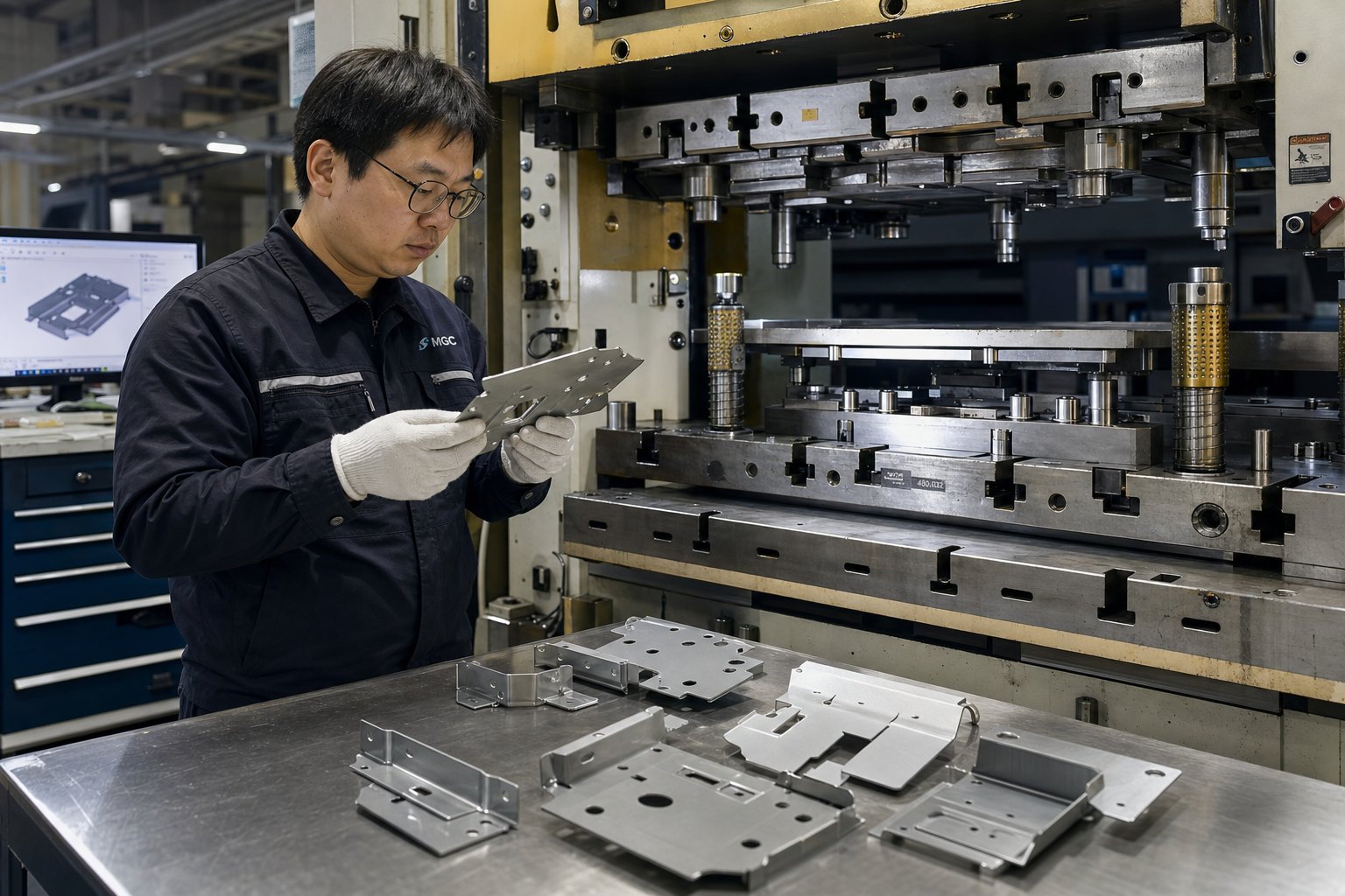
Die Tryout and Part Validation Process
Every stamping die-no matter how thoroughly simulated-goes through a physical tryout process before it is approved for production. Tryout is where the virtual model meets real-world physics, and it is one of the most skill-intensive phases of the entire tooling lifecycle.
Here is what actually happens during tryout on a die stamping press:
- Initial setup and slow-speed cycling: The die is installed in a tryout press and run at very low speed-often single-stroke mode-to verify mechanical clearance, strip feeding, and basic part formation without risking tooling damage.
- Progressive speed increases: Stroke rate is gradually increased toward production speed while technicians monitor for abnormal noise, force spikes, strip feeding issues, and part quality changes that emerge only at higher cycling rates.
- Sample collection and measurement: Parts are pulled at regular intervals and measured against the part drawing using coordinate measuring machines (CMMs), optical comparators, go/no-go gauges, and functional check fixtures. Dimensions are checked against GD&T callouts-not just nominal values but also tolerance bands, true position, and profile specifications.
- Iterative adjustment: Based on measurement data, toolmakers make targeted corrections: adjusting forming radii, shimming die stations, modifying clearances, or reworking specific punches. Each adjustment is followed by another sample run and measurement cycle.
- Production-rate validation: Once parts consistently meet specifications at target stroke rate, a sustained run produces a statistically meaningful sample lot-often 300 to 500 consecutive parts-for Cpk analysis and customer submission.
How many iterations should you realistically expect? For a moderately complex progressive die, plan on two to four tryout rounds as a baseline. Simple blanking dies may validate in one or two iterations. Complex multi-station progressive or transfer tools with deep draws, tight tolerances, or advanced high-strength steels can require five or more rounds before all stations produce conforming parts simultaneously.
A successful die acceptance typically requires three things: all critical dimensions within specified tolerances across a sustained sample lot, surface finish and edge quality meeting workmanship standards, and consistent strip feeding and slug ejection at production speed without operator intervention. Until all three criteria are met simultaneously, the die is not production-ready-regardless of how close individual measurements appear.
Tryout reveals what no simulation can fully predict: the real cost of running a die over time. Every adjustment, every regrind, every spring replacement adds up-and understanding those costs holistically is what separates a smart tooling investment from one that quietly bleeds margin across a multi-year production program.
Stamping Die Tooling Costs and Economic Decision Framework
Every regrind, every spring swap, every tryout iteration from the previous section carries a price tag-and those costs do not exist in isolation. They stack on top of the initial tooling investment, the raw material consumed per hit, and the press time required per part. The real question most engineers and purchasing managers wrestle with is not "how much does the die cost?" but rather "at what point does this investment actually start paying for itself?" Answering that requires a clear-eyed look at what drives stamping die tooling costs, how those costs amortize across production volume, and when alternative manufacturing methods make more economic sense.
What Drives Stamping Die Tooling Costs
Tooling quotes for sheet metal stamping projects can range from $5,000 for simple blanking dies to $100,000 or more for complex progressive dies with multiple forming stations. That enormous spread is not arbitrary. Six primary factors pull the price in different directions:
- Part complexity and number of features: Every hole, bend, embossment, and contour adds a station or operation to the die. A flat washer with one blanking operation is a fundamentally different tooling challenge than a multi-bend automotive bracket with twelve pierced features. More features mean more stations, more precision-ground components, and more engineering hours.
- Die type: As covered earlier, progressive dies cost significantly more than single-station or compound dies because they pack multiple operations into one tool. Transfer dies push costs even higher due to the mechanical transport systems required to move parts between stations.
- Number of stations: In progressive tooling, each station adds cutting punches, forming inserts, strippers, and pilots-all of which must be machined, hardened, and aligned. A six-station die does not cost twice as much as a three-station die, but the relationship is closer to linear than most buyers expect.
- Tool steel grade and surface treatment: A die built with O1 steel and no coating is far cheaper than one using D2 with carbide inserts and TiCN-coated punches. But as discussed in the material selection section, cheaper steel often means shorter die life and higher per-part cost over the production run.
- Tolerance requirements: Tighter tolerances demand finer machining, more precise grinding, and more tryout iterations. Flat features can hold ±0.005 inches or tighter with well-built tooling, but formed features-bends, flanges, drawn walls-require additional engineering effort and often more complex die geometry to control springback and material flow within spec.
- Expected production volume: Volume does not change the die price directly, but it determines what class of tooling you need. A 50,000-piece lifetime run can justify Class C tooling with simpler steels. A five-million-piece automotive program demands Class A construction with premium materials throughout-and the cost difference is substantial.
Most projects in metal stamping manufacturing land in the $15,000 to $50,000 range for moderate complexity parts. Understanding which of these six factors is driving your specific quote gives you leverage-not to negotiate blindly, but to make informed tradeoffs between tooling investment, die life, and part cost.
Per-Part Cost Amortization and Break-Even Thinking
Here is where the economics of stamping manufacturing get interesting. A $40,000 progressive die sounds expensive until you spread that cost across a million parts-suddenly you are looking at four cents per piece for the tooling component alone. Run only 10,000 parts through that same die, and tooling adds $4.00 to every single unit. The math is simple, but its implications are enormous.
Think of it this way: the die is a fixed cost. Press time, material, and labor are variable costs. As volume increases, the fixed tooling cost per piece drops rapidly while the variable costs stay essentially flat. At some crossover point, the total per-part cost of stamped parts undercuts alternative methods that carry no upfront tooling burden but higher per-piece processing costs.
Where does that crossover typically occur? The answer depends on part geometry, material, and which alternative you are comparing against. But practical benchmarks from the industry offer useful guideposts:
- For parts currently produced by laser cutting, stamping typically becomes more cost-effective somewhere above 3,000 to 10,000 units, depending on complexity. Below that range, laser cutting's zero-tooling advantage wins.
- For CNC-machined metal parts stamping replaces, the crossover can occur at even lower volumes if the part geometry is well-suited to forming-since machining carries high per-piece cycle times that stamping eliminates.
- For simple geometries in industrial metal stamping applications, volumes above 10,000 parts per year begin shifting the economics firmly in stamping's favor, especially once blanket order pricing and material efficiency from optimized strip layouts are factored in.
The critical mistake buyers make is evaluating tooling cost in isolation rather than calculating total annual cost-tooling amortization plus per-piece variable cost multiplied by volume. A $5,000 single-station die producing parts at $0.80 each may look cheaper than a $35,000 progressive die producing parts at $0.25 each-until you run the annual volume math and realize the progressive die saves $50,000 per year in production cost.
Stamping Dies vs. Alternative Manufacturing Methods
Stamping is not always the right answer. For low volumes, rapid design iterations, or part geometries that involve extensive three-dimensional machining, other methods may deliver better total economics. The decision framework below helps sort out when stamping die tooling earns its keep versus when alternatives deserve serious consideration:
- Choose stamping when: Annual volumes exceed 10,000-50,000 parts; the part is predominantly formed from flat sheet stock; dimensional consistency across high volumes is critical; per-part cost pressure is the primary driver; and the design is stable enough to justify a fixed tooling investment.
- Consider laser cutting when: Volumes are under 3,000 units; the design is still evolving and may change between production batches; parts are flat or require only simple post-cut bending; and eliminating $15,000 or more in upfront tooling outweighs a higher per-piece processing cost.
- Consider CNC machining when: Parts require tight machined features-threads, precision bores, complex 3D surfaces-that stamping cannot form; volumes are low enough that per-piece machining cost is competitive; or material thickness exceeds practical stamping limits.
- Consider hydroforming when: Parts demand deep, complex three-dimensional shapes with smooth contours that would require multiple draw operations in a conventional die; volumes are moderate; and material utilization is better served by tube or sheet hydroforming geometry.
None of these alternatives are universally cheaper or better. Each occupies a volume-and-geometry sweet spot. The value of metal stamping manufacturing lies specifically in its ability to produce geometrically consistent parts at the lowest per-piece cost once volumes justify the tooling-a threshold that shifts depending on every factor discussed above.
Total cost of ownership extends well beyond the initial purchase order, though. Preventive maintenance-scheduled regrinding at defined hit-count intervals, periodic spring replacement as stripping force degrades, lubrication system upkeep, and eventual die refurbishment-represents an ongoing cost that directly affects long-term economics. A well-maintained Class A die delivering 1,500,000 hits over its lifetime spreads its total cost of ownership across a vastly larger denominator than a neglected die that requires a full rebuild at 400,000 hits. The maintenance investment is real, but the cost of skipping it is always higher.
Understanding these economics puts you in a stronger position at the quoting table. But knowing what to ask, what documents to prepare, and how to evaluate the toolmaker sitting across from you is an entirely different skill set-one that separates buyers who get reliable tooling from those who spend the next two years managing quality escapes and change orders.
How to Source and Evaluate Stamping Die Tooling Suppliers
You understand the economics. You know what die type fits your production volume, which tool steels match your workpiece material, and roughly where your tooling investment should land. The next challenge is entirely different: finding a toolmaker who can actually deliver on those specifications without burying you in change orders, missed timelines, and parts that barely pass inspection on a good day.
Sourcing a metal stamping die is not like ordering a commodity part from a catalog. Every die is custom-engineered, and the quality of that engineering is invisible until the tool is built, installed, and cycling at speed. That asymmetry-where the buyer cannot verify quality until the money is largely spent-makes the front-end process critically important. What you include in the RFQ package, how you evaluate responses, and what questions you ask during supplier visits will determine whether you end up with a production-ready tool or a six-figure headache.
What to Include in Your Stamping Die Tooling RFQ Package
A vague RFQ produces vague quotes-and vague quotes produce surprises. The more precisely you define the project upfront, the tighter the alignment between what you expect and what the toolmaker delivers. Here is the sourcing workflow, step by step:
- Prepare part drawings with GD&T and material callouts. Include a fully dimensioned drawing with geometric dimensioning and tolerancing, material grade, thickness, and any special conditions like temper or surface finish on the incoming coil. As industry case studies consistently show, ambiguous or overtight tolerances on non-critical features are one of the top drivers of unnecessary tooling cost. Identify which dimensions are functionally critical and which can tolerate wider bands-your toolmaker needs this distinction to design efficiently.
- Define annual volume requirements and ramp schedule. Specify not just the total lifetime quantity but also the year-one volume, peak annual demand, and any planned ramp-up or ramp-down. This directly affects tooling class selection-a toolmaker quoting Class A construction for a 20,000-part program is over-engineering the job.
- Specify tolerance and surface finish requirements. Call out critical-to-quality (CTQ) dimensions separately from general tolerances. If specific surfaces must meet Ra values for downstream coating or plating, state those explicitly. Assumptions here cost weeks during tryout.
- Request feasibility feedback before committing to die type. A capable stamping tool and die supplier will push back constructively at this stage-flagging geometry that is difficult to form, suggesting design modifications that reduce tooling complexity, or recommending a different die type than what you assumed. If a supplier simply says "yes" to everything, that is not responsiveness. It is a red flag.
- Evaluate supplier capabilities across design, machining, tryout, and inspection. Request specifics: What CAD/CAM platforms do they use? Do they run simulation in-house? What is the tonnage range of their tryout presses? What metrology equipment is available for part validation?
- Review sample parts from tryout against specifications. Demand first-article inspection reports with full CMM data tied to your GD&T callouts. Visual approval alone is not sufficient-dimensional data must support conformance across the entire tolerance map.
- Confirm die acceptance criteria and maintenance documentation. Before the first chip is cut, agree in writing on what constitutes a successful die acceptance: how many consecutive conforming parts, at what stroke rate, measured against which dimensions. Also request a maintenance manual that documents regrind intervals, spare parts lists, and recommended lubrication schedules.
Skipping any of these steps does not save time. It shifts the problem downstream-into tryout delays, specification disputes, and parts that almost meet print but never quite get there consistently.
Evaluating Tooling Suppliers Beyond Price
Price matters, obviously. But the lowest-cost quote for a metal stamping die frequently becomes the most expensive project once you factor in extended tryout, rework, and production downtime. Evaluating a metal tool and die supplier requires looking past the quoted number and into the infrastructure, engineering depth, and process discipline behind it.
Five capabilities separate serious toolmakers from shops that are simply quoting to win the order:
- In-house design and simulation capability: Suppliers who design progressive dies internally-and validate them with CAE simulation before machining-react faster to problems, iterate more efficiently during tryout, and maintain tighter control over the entire build. Outsourced design creates communication gaps and finger-pointing when quality issues arise.
- Precision machining equipment: Wire EDM, jig grinding, CNC milling with sub-micron positioning, and surface grinding capacity are baseline requirements for any shop building production-grade tooling. Ask about machine age and maintenance schedules-precision equipment that is not calibrated regularly produces components that drift out of spec.
- On-site tryout presses: A supplier without in-house tryout capability is shipping you an untested die. You want to see tryout presses that match or closely replicate the tonnage, bed size, and stroke rate of your production press. Mismatched tryout conditions mask problems that surface immediately when the die moves to your facility.
- Metrology and inspection capacity: CMM equipment, optical measurement systems, and calibrated gauging are non-negotiable. Ask whether inspection is integrated into the tryout workflow or performed only at the end. Continuous measurement during tryout catches drift earlier and reduces total iterations.
- Post-delivery support and willingness to modify: Dies rarely run problem-free for their entire life without some modification. A supplier who treats die delivery as the end of their involvement is not a partner-they are a vendor. Look for toolmakers who maintain records on your die, stock critical spare components, and commit to supporting modifications when your part design evolves or production conditions change.
For automotive stamping die programs and other high-stakes applications, these criteria are not optional-they are the minimum threshold for serious consideration. A metal stamping dies company overview that does not address each of these capabilities should prompt deeper questions, not assumptions.
Full-service suppliers who handle every stage-from feasibility assessment through CAE simulation, precision machining, trial runs, and final inspection under one roof-eliminate the coordination risk that plagues multi-vendor tooling programs and give buyers a single point of accountability from first concept to production handoff.
YICHEN exemplifies this integrated model, covering feasibility analysis, CAE-driven die design, CNC machining, in-house tryout, and dimensional inspection within a single operation. For manufacturers and sourcing managers ready to move from research to an RFQ-ready conversation, their end-to-end capability structure directly addresses the evaluation criteria outlined above-reducing handoff risk and consolidating accountability where it matters most.
From RFQ to Die Acceptance and Production Handoff
The sourcing process does not end when you select a supplier. It continues through design reviews, simulation sign-offs, tryout attendance, and formal die acceptance-and how you manage those milestones determines whether the transition from tooling development to production runs smoothly or stumbles.
A few practical guidelines for the handoff phase:
- Attend tryout in person when possible. Watching your die run on the tryout press gives you information that no report can capture-strip behavior, slug ejection consistency, noise patterns, and the toolmaker's troubleshooting process in real time. It also builds the working relationship you will rely on when modifications are needed down the road.
- Insist on a complete die book. This should include the final die design drawings, bill of materials with steel grades and heat treatment records for every component, spare parts inventory list, maintenance schedule with regrind intervals, and full first-article inspection data. A die without documentation is a die you cannot maintain effectively.
- Define the production handoff criteria explicitly. Agree upfront on how many consecutive conforming parts at production stroke rate constitute a successful acceptance run. Industry norms range from 300 to 500 parts for automation tool & die applications, but complex programs may require larger sample sizes for Cpk validation.
- Plan for engineering change orders (ECOs). Parts evolve. Your customer may revise geometry, adjust tolerances, or change materials after the die is built. Discuss ECO procedures and pricing structures before you need them-when the relationship is collaborative rather than adversarial.
Sourcing stamping die tooling is ultimately a risk management exercise. Every step in the process-from the completeness of your RFQ package to the rigor of your supplier evaluation to the discipline of your acceptance criteria-either reduces or compounds the risk of production problems downstream. The buyers who invest the time upfront to get these details right are the same ones running smooth production lines twelve months later, while their peers are still chasing dimensional issues and negotiating rework charges on tooling that was never properly specified or validated in the first place.
Frequently Asked Questions About Stamping Die Tooling
1. How much does stamping die tooling typically cost?
Stamping die tooling costs range widely based on part complexity, die type, tool steel grade, and tolerance requirements. Simple blanking dies may start around $5,000, while complex progressive dies with multiple forming stations can exceed $100,000. Most moderate-complexity projects fall between $15,000 and $50,000. The key is evaluating total cost of ownership rather than upfront price alone-factoring in die life, maintenance, regrinding intervals, and per-part amortization across your expected production volume. A full-service partner like YICHEN can help you right-size the tooling investment by assessing feasibility, running CAE simulations, and recommending the optimal die class before any steel is cut.
2. What is the difference between progressive dies, transfer dies, and compound dies?
Progressive dies feed a continuous metal strip through multiple stations, each performing a different operation, making them ideal for high-volume small-to-mid-size parts at speeds exceeding 200 strokes per minute. Transfer dies mechanically move individual blanks between separate stations, suited for large or deep-drawn parts that cannot stay on a carrier strip. Compound dies perform multiple cutting operations in a single stroke for superior feature-to-feature accuracy on flat parts but run at slower cycle rates. Choosing the right type depends on matching part geometry, annual volume, and tolerance needs to each die's strengths.
3. What causes burrs on stamped metal parts and how do you fix them?
Burring on stamped parts is most commonly caused by worn or collapsed cutting edges on the punch or die block, or by excessive punch-to-die clearance. As edges dull, burr height increases and the shear band narrows. The corrective approach starts with verifying that clearance matches the workpiece material-typically 5-10% of material thickness per side for mild steel, tighter for stainless. Regrinding restores the cutting edge, but if clearance is the root cause, new inserts with correct dimensions are necessary. Regularly monitoring burr height during production runs catches the problem before scrap rates spike.
4. How do you choose the right tool steel for a stamping die?
Tool steel selection depends on the workpiece material, production volume, and the type of operation each die station performs. D2 steel offers excellent wear resistance for long-run blanking of mild steel. A2 provides a balanced mix of toughness and hardness for mid-volume work. S7 handles heavy forming and shock loads. M2 retains hardness at high temperatures for fast stroke rates, and O1 suits short-run or prototype tooling. Many production dies use multiple grades-harder steels at cutting stations and tougher grades at forming stations-along with surface coatings like TiN or TiCN to extend die life significantly.
5. When does investing in stamping die tooling make more financial sense than laser cutting or CNC machining?
Stamping die tooling generally becomes more cost-effective than laser cutting above 3,000 to 10,000 parts and more economical than CNC machining at even lower volumes for sheet-formed geometries. The crossover point depends on part complexity, material cost, and tolerance requirements. Stamping carries a high fixed tooling cost that amortizes rapidly as volume grows, while alternatives have lower upfront costs but higher per-piece processing expenses. For annual volumes exceeding 10,000-50,000 parts with stable designs, stamping nearly always delivers the lowest total per-part cost. Consulting a full-service toolmaker like YICHEN for a feasibility assessment helps pinpoint the exact break-even for your specific project.


