

Progressive Die Stamping Machine Decoded: Coil In, Precision Out
What a Progressive Die Stamping Machine Actually Does
Imagine a flat coil of metal entering one end of a machine and emerging at the other as a fully formed, precision part-no manual transfers, no secondary setups. That is progressive die stamping in action.
What Is a Progressive Die Stamping Machine
So what is a progressive die? At its core, it is a multi-station tool that performs sequential cutting and forming operations on a metal strip as it advances through a press. The machine built around that tool is what turns concept into continuous production.
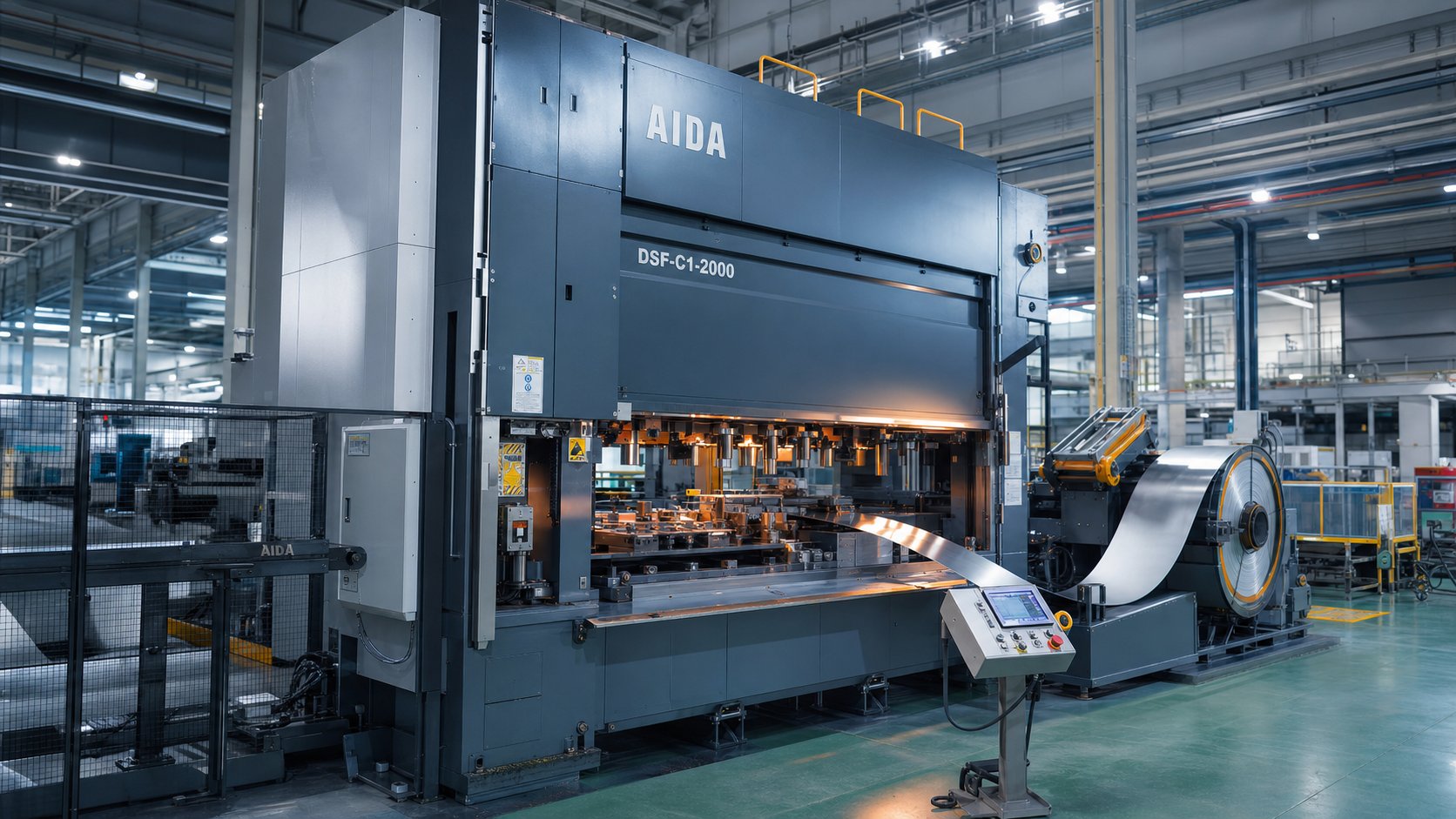
A progressive die stamping machine is an integrated manufacturing system that combines a mechanical or servo press, a multi-station progressive die set, and an automated coil-feeding line to transform flat metal strip into finished parts through continuous, sequential press strokes.
Each stroke of the press advances the strip by a fixed distance-called the feed pitch-while every station performs a distinct operation: piercing, bending, forming, or cutting off. The part remains attached to a carrier strip until the final station separates it as a completed component. This coil-fed, continuous cycle is what gives a progressive stamping machine its speed and repeatability, often producing hundreds of parts per minute with minimal operator intervention.
Why the Machine-Centric Perspective Matters
Most resources focus on progressive stamping as a service or a process description. This article takes a different angle-treating the die stamping machine itself as the primary subject. Why? Because production engineers evaluating capital equipment need to understand how frame rigidity, drive type, and feed precision interact with die performance. Procurement teams comparing sourcing options benefit from knowing which machine specifications influence part quality and total cost of ownership.
Whether you are specifying a new press line or qualifying a supplier's floor capability, the machine is the variable that determines what is achievable in tolerance, speed, and die life. The sections ahead break down each subsystem-from the press frame to the scrap chute-so you can connect equipment choices directly to part outcomes.
Core Components Inside the Machine
A progressive die stamping machine is not a single device-it is a system of subsystems, each performing a specific job that feeds into the next. Strip a machine down to its essentials and you find a press frame providing structural backbone, a die set executing the metalworking, and a coil line delivering raw material with metronomic precision. Understanding how these elements interact helps you predict part quality before the first hit lands.
Press Frame Types and Structural Rigidity
The frame is the skeleton that resists every ounce of forming force. Three common architectures dominate progressive die applications:
- Gap-frame (C-frame) – Offers three-sided access and a compact footprint, making it cost-effective for lighter-tonnage work. The tradeoff is angular deflection under load; because one side is open, the frame flexes slightly with each stroke, which can affect tight-tolerance features.
- Straight-side – Vertical columns on both sides eliminate angular deflection, delivering superior die life and dimensional consistency. This is the go-to choice for progressive dies running at high volumes or demanding close tolerances.
- Tie-rod – Uses pre-stressed tie rods to clamp crown, columns, and bed together. The result is a rigid, vibration-dampened structure suited to heavy-tonnage applications where even micro-level deflection degrades part accuracy.
Why does rigidity matter so much? Every thousandth of an inch the frame deflects translates directly into dimensional variation on your stamped part. A straight-side or tie-rod press keeps tooling punches aligned throughout the stroke, preserving clearances that determine burr height, hole quality, and formed-feature accuracy.
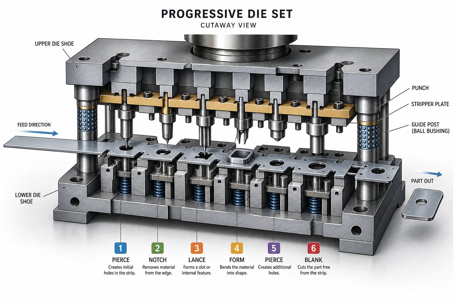
Die Set Layout and Station Sequencing
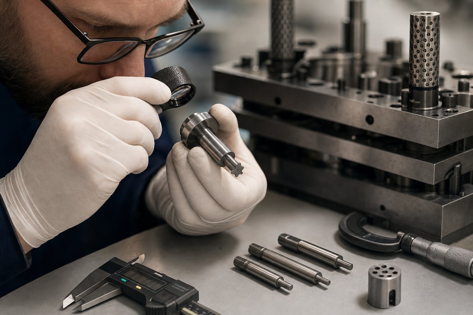
Inside the press sits the stamping die-a precision-machined assembly of upper and lower shoes, guide posts, punches, die buttons, pilots, strippers, and springs. Progressive dies arrange these elements across multiple stations, each dedicated to a specific operation:
- Piercing – Metal punching tools create holes, slots, or pilot features in the strip.
- Blanking – Removes larger sections of material to define part perimeter geometry.
- Forming and bending – Shapes the flat blank into three-dimensional features.
- Coining – Applies high compressive force for tight dimensional control on critical surfaces.
- Cutoff – Separates the finished part from the carrier strip.
Station sequencing follows a deliberate logic: datum features are punched early for positional accuracy, forming operations come after piercing to avoid distortion, and cutoff is always last. The spacing between stations-equal to the feed pitch-determines how far the strip advances per stroke. Well-designed progressive die tooling balances station count against strip stability, ensuring every operation has room to perform without compromising the carrier.
Feeding, Guiding, and Scrap Systems
Precision stamping dies are only as accurate as the material delivery system feeding them. A typical coil line includes three integrated functions:
- Uncoiler – Supports and pays off the coil at a controlled tension.
- Straightener (leveler) – Passes the strip through adjustable rollers that remove coil-set curvature, delivering flat stock to the die.
- Servo or roll feeder – Advances the strip a precise distance each cycle, then holds it stationary during the press stroke.
Once the strip enters the die, pilot pins engage pre-punched holes to register its exact lateral and longitudinal position at every station. Strip guidance rails keep the material centered while lifters raise it above the die surface between strokes, preventing drag marks and ensuring smooth progression.
Scrap is an inevitable byproduct. Slugs from piercing fall through die openings into chutes below the bolster, while skeleton strip exits the back of the press onto a scrap conveyor or chopper. Reliable scrap removal prevents slug pulling-a condition where a slug rides back up with the punch and damages the next part or the die itself.
| Component | Primary Function | Impact on Part Quality |
|---|---|---|
| Press frame | Resists forming forces, maintains alignment | Controls deflection; directly affects dimensional accuracy and die life |
| Die set (stamping dies) | Performs sequential cutting, forming, and separation | Determines feature geometry, tolerances, and surface finish |
| Coil feeder and straightener | Delivers flat strip at precise feed pitch | Ensures consistent progression; prevents misfeeds and positional errors |
| Pilot system | Registers strip position at each station | Maintains station-to-station alignment within microns |
| Strip guidance rails | Centers strip laterally through the die | Prevents skew that causes uneven blanking or forming |
| Scrap removal (chutes and choppers) | Ejects slugs and skeleton strip | Prevents slug pulling, die crashes, and surface defects |
When every subsystem works in concert-frame absorbing load without deflection, feeder delivering strip on pitch, pilots locking position, and scrap clearing cleanly-the result is a unified system capable of producing thousands of identical parts per hour. The next variable in the equation is motion itself: how the press converts stored energy into the controlled slide movement that drives each station through its forming cycle.
How the Progressive Stamping Process Operates
You know what sits inside the machine. The real question is: how does a stamping press work when every subsystem fires together in a continuous cycle? The answer lives in the progressive die stamping process itself-a choreographed sequence where a flat coil becomes a finished part one station at a time, without ever leaving the strip until the final cut.
Step-by-Step Strip Progression
Picture a coil of metal loaded onto the uncoiler. The straightener removes curvature, and the servo feeder advances the strip into the die by a fixed distance-the progression pitch. That pitch equals the center-to-center spacing of the stations and determines part flow through the entire tool. Every stroke of the press repeats this feed-and-form cycle.
Here is the progressive stamping process broken into its core stages:
- Coil loading and strip feeding – The feeder advances flat stock into the die opening. Initial pilot holes are punched in an early station to establish registration.
- Pilot pin engagement – As the upper die descends, precision pilot pins enter the pre-punched holes, locking the strip into exact lateral and longitudinal position before any cutting force is applied.
- Piercing and lancing – Punches die cut metal to create holes, slots, and relief features that prepare the blank for subsequent forming.
- Forming and drawing – Stations bend, coin, or draw material into three-dimensional shapes. The carrier strip flexes at engineered attachment points to accommodate vertical movement without losing pitch accuracy.
- Trimming – Excess material is sheared away to refine the part perimeter to final geometry.
- Cutoff and ejection – The last station severs the completed part from the carrier. Finished progressive die stampings drop into a chute or conveyor below the press, ready for packaging or secondary processing.
Strip layout design governs this entire sequence. Engineers determine how parts nest on the strip, where bridges maintain structural integrity, and what order operations follow to avoid distortion. A well-optimized layout targets over 75% material utilization while keeping the carrier robust enough to feed reliably at speed.
What High-Speed Stamping Demands from the Machine
Standard progressive die applications run comfortably between 100 and 400 strokes per minute. Push into high speed progressive die stamping territory, and presses can exceed 1,000 strokes per minute. At those rates, every millisecond of slide dwell, feed motion, and pilot engagement is compressed.
What changes at speed? Three things tighten simultaneously:
- Machine rigidity – Frame deflection that is negligible at 200 SPM becomes cumulative at 1,000-plus. Straight-side or tie-rod presses are essential to maintain die alignment under rapid cyclic loading.
- Lubrication precision – Higher speeds generate more heat and friction. Micro-spray or drip systems must deliver lubricant to exact contact zones without pooling or starving adjacent stations.
- Feed accuracy – The servo feeder must accelerate, position, and decelerate the strip within a fraction of the press cycle. Even a 0.05 mm feed error compounds across stations, causing misregistration and scrap.
High-speed capability is not just about a faster motor. It is the combined result of press dynamics, feed response, die clearances, and scrap evacuation all operating within tighter timing windows. The drive system behind that slide motion-mechanical, servo, or hydraulic-shapes what speeds and forming profiles are achievable.
Press Types That Power Progressive Die Operations
Every progressive stamping press converts stored energy into the controlled slide motion that drives punches through metal. But how that energy reaches the slide-and how it behaves during the critical working portion of the stroke-varies dramatically depending on the drive system. The choice between mechanical, servo, and hydraulic directly influences production speed, part quality, die longevity, and the forming complexity you can achieve.
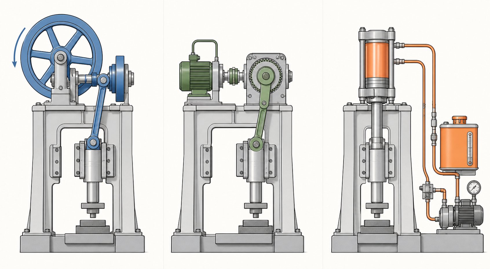
Mechanical Presses and Link Motion Drives
The workhorse of high-volume progressive die stamping is the mechanical press. A flywheel stores rotational energy, and a crankshaft or eccentric gear converts that energy into reciprocating slide motion. The result is a fixed stroke curve-fast at the top, slower near bottom dead center-delivering consistent cycle times that suit repetitive production.
Mechanical presses excel at speed. Short cycle times and low energy consumption per stroke make them ideal for blanking, shallow forming, and piercing operations where full tonnage is only needed briefly at the bottom of the stroke. The tradeoff? Limited flexibility. The stroke profile is determined by geometry, not software, so you get the same motion every cycle regardless of what the part demands.
This is where a link motion press changes the equation. Instead of a simple crank, link motion drives use a multi-link mechanism that reshapes the slide velocity curve. During the working portion of the stroke, slide velocity decreases by up to 40%, while speed increases through the non-working portion to maintain high production rates. Imagine a press that slows down exactly when metal is being formed, then sprints back to the top for the next hit.
The practical benefits for progressive die operations are significant:
- Reduced die impact – Lower approach velocity means less shock on tooling at engagement, extending punch and die button life.
- Less spring-back – Longer dwell under pressure improves metal plasticity, producing formed features closer to net shape without re-striking.
- Higher effective SPM – Progressive die link motion drives can increase operating speeds by at least 25% compared to standard crank motion at equivalent part quality.
- Lower noise and vibration – Reduced snap-through forces translate to a quieter, smoother-running die stamping press.
Dynamic balancing complements link motion by counteracting the inertial forces generated by the reciprocating slide mass. At high speeds, an unbalanced press transmits vibration into the foundation, the die, and ultimately the part. Counterbalance systems-either mechanical weights or pneumatic cylinders-neutralize these forces, keeping the press stable and reducing fatigue on both the frame and tooling.
Servo Presses for Variable Stroke Control
What if you could program the slide to move differently on every job-or even at different points within a single stroke? That is what a servo progressive die press delivers. A high-torque servo motor replaces the flywheel and clutch, giving full control over slide position, velocity, and acceleration throughout the cycle.
Servo presses bring several capabilities that conventional mechanical drives cannot match:
- Programmable stroke profiles – Slow the slide for deep draws, dwell at bottom dead center for coining, or pulse through a forming sequence. You design the motion curve to fit the part, not the other way around.
- Variable speed within a single cycle – Approach quickly, form slowly, return at maximum velocity. This flexibility supports complex multi-station forming without compromising throughput.
- Energy efficiency – The motor only draws power when performing work, and regenerative braking recovers energy during deceleration.
- Reduced die wear – Controlling approach velocity at the moment of punch engagement reduces impact loading, a benefit comparable to the advantages of link motion but infinitely adjustable via software.
The emerging role of servo technology in progressive stamping centers on jobs that combine multiple forming types-piercing plus deep drawing plus coining-in a single die. A fixed stroke curve forces compromises across stations. A servo press eliminates those compromises by tailoring motion to each operation's ideal forming velocity.
Choosing Press Tonnage and Bed Size
Selecting the right tonnage for a progressive stamping press is not as simple as matching the press rating to the thickest material you plan to run. Tonnage demand is cumulative across every active station in the die. You need to account for:
- Material thickness and tensile strength – Thicker or harder materials require proportionally more cutting and forming force per station.
- Number of active stations – A 20-station die with simultaneous piercing, forming, and coining loads can peak well above what any single station demands alone.
- Forming forces – Drawing and coining generate higher tonnage than piercing. Complex bends with tight radii concentrate force on smaller die areas.
A common guideline is to size the press at 60–70% of rated capacity for the calculated peak load. This margin protects the frame, bearings, and drive from overload while giving headroom for material variation and die sharpening cycles that gradually increase cutting force.
Bed size matters equally. The die must fit within the bolster area with enough clearance for scrap chutes, strip support, and quick die change clamping. If you are running a wide strip for multi-out layouts, a larger left-to-right bed dimension becomes mandatory. Matching tonnage and bed size together ensures the press can physically accommodate and mechanically support the die throughout its service life.
| Criteria | Mechanical Press | Servo Press | Hydraulic Press |
|---|---|---|---|
| Speed (strokes per minute) | High to very high | Adjustable (low to high) | Low to moderate |
| Force consistency through stroke | Peak force near BDC only | Programmable force curve | Full tonnage at any point |
| Stroke profile flexibility | Fixed (improved with link motion) | Fully programmable | Adjustable but slower |
| Energy efficiency | High (flywheel storage) | Very high (regenerative) | Lower (continuous pump) |
| Die life impact | Good (excellent with link motion) | Excellent (controlled engagement) | Good (low-speed approach) |
| Typical progressive die applications | High-speed blanking, piercing, shallow forming | Complex multi-form dies, mixed operations | Deep drawing, heavy-gauge forming |
Hydraulic presses deserve mention for completeness. They deliver full tonnage at any point in the stroke-useful for deep drawing or operations requiring sustained force-but their slower cycle times limit throughput in high-volume progressive applications. You will find them more often powering transfer dies or standalone forming operations than running multi-station progressive tools at production speed.
The drive system defines what a progressive die press can do, but material is what it does it to. Different metals and alloys bring their own demands in forming force, feed behavior, and lubrication strategy-factors that circle back to press selection in ways that are easy to overlook.
Material Selection for Progressive Die Stamping
A press can deliver perfect stroke dynamics and a die can feature flawless station geometry, yet the wrong material choice will still produce scrap. Progressive metal stamping puts unique demands on the coil stock passing through it-the strip must feed cleanly, form without cracking, and shear with predictable burr characteristics across hundreds of strokes per minute. Choosing the right metal is not just a design decision; it directly influences which machine settings, tooling clearances, and lubrication strategies will succeed.
Compatible Metals and Alloy Families
Progressive die metal stamping accommodates a broad range of ferrous and nonferrous materials. Each alloy family brings a distinct balance of strength, formability, and cost that shapes how the die and press must be configured.
- Low-carbon steel (C1008–C1026) – The most widely processed material in steel progressive stamping. High ductility, low cost, and predictable shear behavior make it the default choice for brackets, housings, and structural components. Zinc or nickel plating can add corrosion resistance post-stamping.
- Stainless steel (300 and 400 series) – Offers corrosion resistance and strength at the expense of higher forming forces and more aggressive die wear. Austenitic grades like 304 work-harden quickly, demanding robust press tonnage and carefully controlled punch-to-die clearances.
- Copper and beryllium copper – Copper progressive stamping dominates electrical connector and terminal production thanks to excellent conductivity, corrosion resistance, and ductility. Beryllium copper adds spring properties and fatigue resistance for contact applications requiring high cycle life.
- Brass (C260–C360) – Combines good formability with thermal and electrical conductivity. Its relatively soft nature reduces die wear, making it suitable for decorative hardware, lock components, and high-speed progressive runs.
- Aluminum (1100, 3003, 5052, 6061) – Delivers a high strength-to-weight ratio with excellent formability in softer tempers. Aluminum stamping tools require wider punch-to-die clearances compared to steel because the material tends to gall and build up on tooling surfaces without proper lubrication.
The best material is rarely the strongest one-it is the one whose mechanical behavior aligns with the part geometry, production volume, and available press capability.
Thickness Ranges and Coil Specifications
Progressive stamping materials are supplied as coil stock in standardized gauge thicknesses. Typical processing ranges span from approximately 0.004 in. (0.1 mm) for micro-precision electronic terminals up to 0.250 in. (6.35 mm) for heavy structural brackets. The sweet spot for most progressive applications falls between 0.015 in. and 0.125 in. (roughly 28 gauge to 11 gauge).
Coil widths commonly range from under 1 in. for single-out narrow-strip dies to over 24 in. for wide multi-out layouts. Wider strips require presses with larger bed dimensions and feeders capable of handling heavier coil weights without introducing strip camber or edge wave.
Sticking to industry-standard gauge thicknesses keeps cost down because these sizes are commonly stocked by service centers. Custom thicknesses or specialty alloys often require mill-minimum orders-sometimes truckload quantities-which can strain budgets on lower-volume programs.
How Material Properties Influence Machine Settings
Three mechanical properties drive the interaction between progressive stamping materials and the press: tensile strength, ductility (elongation percentage), and hardness. Each one shapes how you configure the equipment.
Tensile strength determines cutting and forming force requirements. A strip of 304 stainless at 85 ksi ultimate tensile strength demands roughly twice the piercing tonnage of low-carbon steel at 45 ksi for identical hole geometry. That difference compounds across every active station, pushing total tonnage requirements higher and often dictating a larger press.
Ductility governs how aggressively the die can form material without fracture. High-elongation metals like copper (over 40% elongation) tolerate tight bend radii and deep draws. Lower-ductility alloys such as spring steel or hard-temper stainless require gentler forming angles, more stations to distribute strain, and sometimes servo press profiles that slow the slide during the working stroke.
Hardness correlates with die wear rate. Harder materials abrade punch and die surfaces faster, shortening sharpening intervals. Carbon steel progressive stamping on softer grades (Rockwell B 55–70) produces long die runs with minimal maintenance, while stainless or high-strength alloys may cut die life in half if tooling steels and coatings are not upgraded accordingly.
Lubrication strategy also shifts with material type. Stainless steels and aluminum both require heavier-duty lubricants-chlorinated or synthetic films-to prevent galling and built-up edge on punches. Standard petroleum-based oils work well for mild steel and brass. At high speeds, lubrication delivery switches from flood systems to precision micro-spray applicators that target specific punch faces and forming stations without contaminating adjacent operations.
Press speed adjustments follow similar logic. Softer, more ductile materials tolerate higher stroke rates because they shear cleanly and generate less heat. Harder alloys benefit from reduced speed or link-motion drives that slow the slide at engagement, lowering impact shock and extending tool life.
| Material Type | Typical Thickness Range | Key Processing Considerations |
|---|---|---|
| Low-carbon steel | 0.015 in. – 0.250 in. | Low forming force, high ductility, standard lubrication. Widest range of press compatibility. |
| Stainless steel (austenitic) | 0.010 in. – 0.125 in. | High tonnage demand, rapid work-hardening, anti-galling lubricants required. Tighter punch-to-die clearances. |
| Copper / Beryllium copper | 0.004 in. – 0.080 in. | Excellent formability, soft material reduces die wear. Thin gauges common for electrical contacts. |
| Brass | 0.008 in. – 0.125 in. | Good ductility, moderate strength. Compatible with high-speed stamping; minimal lubricant needed. |
| Aluminum | 0.010 in. – 0.190 in. | Wider die clearances needed, galling tendency. Aluminum stamping tools benefit from coated or polished punch surfaces. |
Material selection is never an isolated decision-it feeds forward into tonnage calculations, die steel selection, maintenance intervals, and even the comparison between progressive and alternative stamping methods. When the material pushes die complexity or press capacity to their limits, it may be time to ask whether a progressive approach is still the most cost-effective path.
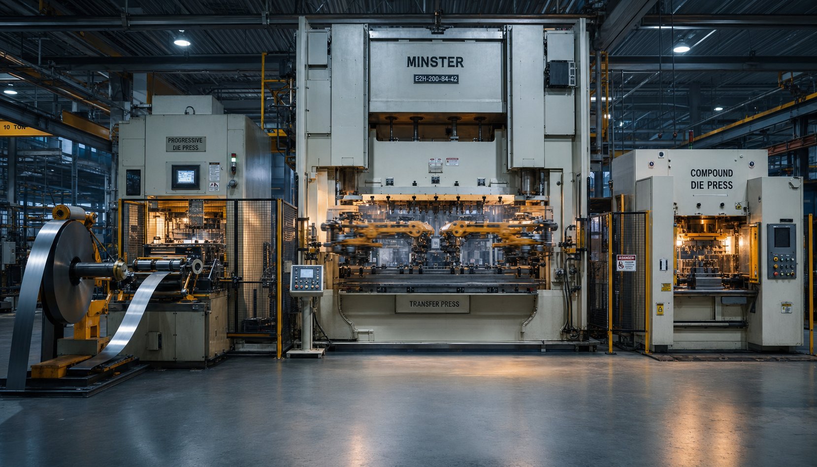
Comparing Progressive Dies to Alternative Stamping Methods
A progressive die is a powerful tool, but it is not the only one in the metalworking toolbox. When part geometry gets too large, volumes run too low, or forming depth exceeds what a carrier strip can handle, alternative methods often deliver better economics or better parts. Knowing where progressive die and stamping operations excel-and where they do not-prevents expensive mismatches between process and product.
Progressive vs Transfer vs Compound Stamping
Three stamping methods dominate precision metal part production. Each uses a fundamentally different approach to move material through operations, and that difference determines which jobs they handle best.
Progressive die stamping keeps the workpiece attached to a carrier strip throughout the entire sequence. The strip advances station to station inside a single die set, with the finished part separated only at the final cutoff. This continuous-feed approach supports extremely high speeds-often 100 to over 1,000 strokes per minute-and delivers the lowest per-piece cost at volume because setup time is minimal and labor involvement is near zero once the press is running.
Transfer die stamping separates the blank from the strip early in the process. Mechanical fingers or transfer arms then move the individual workpiece between independent die stations. Because the part is free-standing, transfer dies can punch as deep as the raw material allows without being constrained by carrier strip geometry. This makes transfer stamping the preferred method for large parts, deep-drawn shells, and components requiring operations on multiple faces.
Compound die stamping performs multiple cutting operations-blanking and piercing, for example-in a single press stroke. The result is a flat, dimensionally precise part with excellent concentricity between features. Compound dies are simpler and less expensive to build than progressive tooling, but they handle only flat geometry and produce one part per stroke without forming capability.
Multi-slide forming deserves mention as a fourth option. Multi-slide machines use cams and sliding tools approaching the strip from multiple directions simultaneously, making them ideal for small parts with complex bends in multiple planes-clips, springs, wire forms, and connectors that would require excessive stations in a conventional progressive die.
| Criteria | Progressive Die Stamping | Transfer Die Stamping | Compound Die Stamping |
|---|---|---|---|
| Ideal annual volume | 50,000 to millions | 10,000 to 500,000+ | 5,000 to 200,000 |
| Part complexity | Moderate (limited draw depth) | High (deep draws, large parts) | Low (flat parts only) |
| Typical tooling cost | $15,000 – $60,000+ | $100,000 – $500,000+ | $5,000 – $20,000 |
| Per-piece cost at scale | Lowest | Moderate | Low to moderate |
| Production speed | Very high (100–1,000+ SPM) | Moderate (15–60 SPM) | Moderate to high |
| Part size range | Small to medium | Medium to large | Small to medium (flat) |
| Setup and changeover | Low (single die, automated feed) | Higher (multiple stations, transfer calibration) | Low |
Understanding these types of stamping dies in relation to your specific part requirements eliminates guesswork. A bracket that fits in your palm and ships in quantities of 500,000 annually? Progressive is almost certainly the answer. A deep-drawn automotive cup that exceeds strip-width limitations? Transfer takes over.
When Progressive Die Stamping Is Not the Right Fit
Sounds like progressive stamping wins on speed and cost every time? Not quite. Several scenarios push projects toward alternative methods:
- Part size exceeds strip capacity – Progressive dies are limited by coil width and press bed dimensions. Parts wider than roughly 24 inches or requiring large flat area often cannot be nested efficiently on a strip, making transfer die stamping or tandem line dies more practical.
- Deep draw depth surpasses carrier strip limits – When draw ratios require the material to move vertically beyond what the carrier strip can tolerate without buckling or tearing, the part needs to be free-standing. Transfer presses handle this naturally.
- Volume is too low to amortize tooling – A progressive die averaging $15,000 to $60,000 only makes sense when production quantities spread that investment thin enough to compete with simpler methods. Below certain thresholds, laser cutting, press brake forming, or compound die stamping costs less per part.
- Part geometry demands multi-face operations – Progressive tooling works in one axis of press motion. If the part requires side-piercing, threading, knurling, or operations from multiple directions simultaneously, transfer or multi-slide methods offer more geometric freedom.
- Tight flatness on complex blanks – Compound dies produce flatter parts than progressive dies because the part is formed in a single stroke without being dragged through multiple stations. For washers, shims, or lamination stacks where flatness is the critical spec, compound tooling wins.
Recognizing these boundaries early saves engineering time and avoids forcing a progressive solution where the process will fight the geometry.
Cost Structure and Volume Break-Even Logic
The economics of long run progressive stamping follow a simple but powerful curve: high fixed cost up front, vanishingly low variable cost per hit. Understanding where the break-even point falls determines whether progressive tooling is a smart investment or an expensive over-commitment.
Consider a concrete example. A mid-complexity progressive die might cost $30,000 to design and build. Once running, it produces parts at $0.50 each. The same part made with laser cutting and press brake forming might cost $5.00 per piece with no tooling investment. The math is straightforward:
- At 1,000 parts annually, the progressive die adds $30 per part in amortized tooling cost-far exceeding the laser-cut alternative.
- At 10,000 parts, tooling amortization drops to $3.00 per part, bringing total progressive cost to $3.50 versus $5.00 for alternatives. Break-even is approaching.
- At 20,000 parts, the progressive route costs $2.00 per part total ($1.50 amortized tooling plus $0.50 run cost), saving roughly $60,000 annually compared to piece-part methods.
- Beyond 50,000 parts, amortization becomes negligible and the progressive die delivers its lowest cost-per-piece advantage-often a 10:1 ratio over non-tooled methods.
For most progressive applications, the break-even threshold lands between 10,000 and 20,000 parts annually. Below that range, simpler tooling or non-tooled fabrication methods keep costs lower. Above it, progressive stamping pulls away decisively on unit economics.
Transfer dies follow a different curve. Their higher tooling cost ($100,000+) pushes the break-even further out, but they handle parts that progressive dies physically cannot produce. Compound dies occupy the budget-friendly end-lower tooling investment, faster build time, but limited to flat geometry and moderate speeds.
The decision framework boils down to three questions:
- Can the part geometry physically run in a progressive die without exceeding size or depth limitations?
- Does the annual volume justify the tooling investment at a competitive per-piece cost?
- Does the production timeline support the lead time required to design, build, and validate the die?
If all three answers are yes, progressive die and stamping operations will almost always deliver the best combination of speed, repeatability, and total cost. If any answer is no, the alternatives deserve serious evaluation.
The method comparison clarifies which approach fits a given production profile-but within progressive stamping itself, the range of applications is remarkably broad. The same fundamental process that stamps a copper micro-terminal for a smartphone connector also produces a steel structural bracket for an automotive chassis, with machine specs and precision standards shifting dramatically between sectors.
Industry Applications and Precision Standards
A copper terminal thinner than a credit card and a steel structural bracket you could stand on both come off progressive dies. The difference is not just material-it is the entire machine specification behind each part. Tonnage, press type, stroke speed, and quality monitoring all shift depending on which industry the finished component serves.
Automotive and Electronics Applications
Automotive components progressive stamping accounts for a massive share of the global progressive die market. Think brackets securing wiring harnesses, structural reinforcements inside door assemblies, connectors linking ECU modules, and fuel system components requiring consistent sealing surfaces. These parts demand high tonnage presses-often 200 to 600 tons-because material gauges tend to be heavier (0.040 in. to 0.125 in. mild steel or high-strength low-alloy grades) and die stations are numerous.
Die life expectations in automotive are equally aggressive. Production runs reaching millions of hits per year mean the press must hold alignment stroke after stroke without cumulative frame fatigue degrading part dimensions. Straight-side presses with link motion drives dominate here because they combine the rigidity needed for heavy blanking with reduced shock loading that extends tooling life across long campaigns.
Electronics applications flip the equation. Instead of high tonnage, the priority shifts to micro-precision and speed. Terminals, shielding cans, battery contacts, and connector housings are stamped from thin-gauge copper, phosphor bronze, or stainless strip-often below 0.020 in.-at speeds exceeding 800 strokes per minute. Machine rigidity still matters, but the critical variable becomes feed accuracy. A positioning error of 0.05 mm on a terminal with 0.3 mm pitch spacing produces scrap. Servo feeders with closed-loop encoders and presses with minimal slide-to-bolster clearance keep progressive precision metal stampings within the ±0.001 in. (±0.025 mm) tolerances these parts require.
Medical and Aerospace Precision Requirements
Medical progressive stamping raises the bar further. Surgical instrument components, implantable device housings, and diagnostic equipment parts must meet tolerances as tight as ±0.0002 inches while being stamped from biocompatible alloys like 316L stainless steel, titanium, or cobalt-chromium. The machine implications are significant: servo presses with programmable dwell at bottom dead center allow controlled coining and forming that minimizes springback on hard-to-form medical alloys. Surface finish requirements-often Ra 16 micro-inches or better-demand polished die components and precisely maintained punch-to-die clearances.
Aerospace shares this obsession with dimensional consistency. Structural clips, shielding panels, and connector components for avionics carry tolerances of ±0.0005 inches alongside strict material traceability. Press tonnage monitoring must log force data per stroke so that any anomaly triggering an out-of-spec condition is traceable to a specific part.
HVAC and construction applications, by contrast, prioritize volume and durability over extreme precision. Heat exchanger fins, mounting brackets, and ductwork connectors typically hold ±0.005 in. tolerances-more relaxed, but still reliant on consistent press operation over multi-million-piece runs.
- Automotive – Brackets, connectors, structural reinforcements, fuel system parts. Typical tolerance: ±0.001 in. to ±0.002 in. High tonnage, long die life, link motion drives preferred.
- Electronics – Terminals, shielding cans, battery contacts, connector housings. Typical tolerance: ±0.001 in. Thin gauge, high speed (800+ SPM), servo feed precision critical.
- Medical devices – Surgical instrument parts, implantable housings, diagnostic components. Typical tolerance: ±0.0002 in. to ±0.0005 in. Biocompatible alloys, servo press dwell, polished tooling.
- Aerospace – Structural clips, avionics connectors, shielding panels. Typical tolerance: ±0.0005 in. Full tonnage traceability, material certification required.
- HVAC / Construction – Heat exchanger fins, mounting hardware, ductwork brackets. Typical tolerance: ±0.005 in. High volume, moderate tonnage, standard mechanical presses.
Quality Control and In-Die Sensing
Precision die stamping at these tolerance levels only works if the machine can detect problems before they become defective shipments. Modern progressive stamping integrates quality systems directly into the press and die, creating a closed feedback loop.
In-die sensors continuously monitor force, displacement, and material presence at critical stations. If a piercing punch encounters resistance outside the expected range-indicating a dull cutting edge or a misfeed-the sensor signals the press control to stop immediately rather than produce hundreds of bad parts before an operator notices.
Automated optical inspection adds another layer. High-speed CCD vision systems operating at up to 1,000 frames per second measure critical dimensions on every part as it exits the die, with measurement resolution down to 0.01 mm. Parts falling outside tolerance are automatically diverted before reaching the packaging line.
Tonnage monitors on the press itself track peak force per stroke and trend it over time. A gradual upward drift signals die wear or material variation long before tolerances are breached, giving maintenance teams early warning to schedule sharpening. Together, these systems transform a progressive die stamping machine from a production tool into a self-policing manufacturing cell-one that refuses to ship what it cannot verify.
Keeping that verification system healthy, and the die performing within spec over millions of cycles, depends on a disciplined maintenance strategy that most operations underestimate.
Maintenance Practices That Extend Die Life
A progressive stamping tool running at 400 strokes per minute accumulates over a million hits in a single production week. Every one of those hits generates cutting force, friction, and heat that gradually degrade punch edges, forming surfaces, and guide components. Without a systematic maintenance program, die life shortens unpredictably, part quality drifts, and unplanned downtime eats into production schedules.
Preventive Maintenance Schedules and Die Sharpening
Effective progressive tooling maintenance is not reactive-it follows a rhythm tied to stroke count rather than calendar dates. The goal, as stamping experts emphasize, is consistency: identify every area of the tool that degrades over time, document how to service it, and execute identically every cycle.
Die sharpening intervals depend on three primary factors:
- Material abrasiveness – Stainless steel and high-strength low-alloy grades wear punch edges far faster than soft copper or mild steel. A die running 304 stainless may require sharpening every 50,000 to 100,000 hits, while the same geometry in C1010 steel can push 250,000 or more between services.
- Stroke count accumulation – Most shops track hits per service interval and trend actual sharpening needs against targets. Consistent intervals-not reactive responses to quality escapes-produce predictable die life.
- Lubrication quality – Inadequate or inconsistent lubricant delivery accelerates edge wear, increases heat buildup, and promotes galling on forming surfaces. Micro-spray systems applying the correct film weight at each station can extend sharpening intervals by 30% or more compared to flood lubrication that misses critical contact zones.
A structured maintenance checklist keeps every service consistent regardless of which technician performs the work:
- Inspect all cutting edges under magnification; sharpen when burr height exceeds the acceptable threshold for the application (typically 10% of material thickness).
- Check pilot pin diameter and length-worn pilots cause strip misregistration that compounds across stations.
- Inspect form punches and die inserts for measurable wear; replace or polish per documented procedure.
- Verify spring forces on strippers, stage tooling lifters, and pressure pads; replace weakened springs before they affect strip control.
- Confirm timing on all inserts and check die shut height against the baseline measurement.
- Clean scrap chutes and inspect for slug buildup that could cause slug pulling on subsequent runs.
- Document sharpening stock removed, total die height change, and component replacements for the service history log.
The discipline behind this checklist is more important than the checklist itself. As one veteran die maintenance manager puts it: quality workmanship is defined as consistency. If a service tech grinds a different amount off the cutting section each time, hits per service will swing unpredictably-making continuous improvement impossible.
Quick Die Change and SMED Principles
Every minute a press sits idle during a die change is a minute it produces zero parts. In high-mix progressive stamping environments where multiple part numbers share the same press, changeover time directly impacts throughput and delivery performance. This is where SMED-Single-Minute Exchange of Dies-transforms the equation.
Developed by industrial engineer Shigeo Shingo, the SMED methodology targets reducing any changeover to under 10 minutes by separating setup tasks into two categories:
- Internal elements – Steps that can only happen while the press is stopped (bolting the die into the bolster, connecting sensors, verifying shut height).
- External elements – Steps that can be completed while the press is still running the previous job (staging the next die on a rolling cart, pre-connecting air and electrical lines, loading the coil onto the uncoiler).
The principle is simple: convert as many internal steps to external as possible, then streamline whatever internal tasks remain. In practice, progressive stamping operations implement SMED through quick die change (QDC) systems that include hydraulic or pneumatic die clamps, standardized bolster plates with T-slot or ball-lock patterns, powered die transfer carts, and preset shut-height memory in the press controller.
A well-executed QDC system can reduce a changeover from 45 minutes down to under 8-freeing the press to run smaller lot sizes economically and respond faster to shifting production schedules. The combination of SMED principles with stage tooling preparation-where the incoming die, coil, and feeder settings are fully assembled offline-eliminates the scramble that typically accompanies job changes.
Extending Die Life Through Machine Optimization
Die life is not just a function of tool steel quality and maintenance frequency. The press itself plays an equal role. A misaligned press or one running without proper tonnage monitoring can destroy a well-built die in a fraction of its expected service life.
Press alignment matters at the micron level. Parallelism between the slide face and the bolster surface must stay within 0.001 inches per foot of bed width. If the slide cocks under load, it creates uneven force distribution across the die-overloading one side while underloading the other. The result is accelerated wear on punches, uneven burr patterns, and premature die failure on the high-load side.
Tonnage monitoring provides early warning before damage occurs. A properly configured monitor learns the normal peak force for each die and sets high- and low-limit setpoints within a tight window-typically ±15 to 20% of the expected peak. If tonnage trends upward over successive runs, it signals that cutting edges are dulling and sharpening is due. A sudden spike flags a slug buildup, double-part condition, or misfeed that would otherwise crash the die. The monitor must be wired into the press stop circuit and set to job-specific limits-not left at full press capacity where it provides no meaningful protection.
Stamping die lifters and nitrogen springs serve a less obvious but equally critical role in preserving die life. Lifters raise the strip above the die surface between strokes, allowing it to advance freely without dragging across form details or cutting edges. Without adequate lift, the strip scrapes across sharp edges and deposits material on polished surfaces-degrading both strip quality and tooling finish.
Nitrogen gas springs are preferred over mechanical coil springs in many progressive tooling applications because they deliver consistent force throughout their stroke without fatigue-related force loss over time. They also provide the high initial force needed to positively strip material off punches, preventing slug pulling. As a progressive stamping tool accumulates millions of hits, nitrogen springs maintain their rated pressure while coil springs gradually weaken-making nitrogen the more reliable choice for critical stripping and lifting functions in demanding production environments.
Taken together-structured sharpening schedules, rapid changeovers, precise press alignment, active tonnage control, and properly specified lifter systems-these practices determine whether a die delivers 500,000 hits or 5 million before requiring major refurbishment. The investment in maintenance discipline pays back through predictable quality, fewer unplanned stops, and a cost-per-hit that keeps progressive stamping competitive against alternative methods at high volume.
Selecting the Right Machine and Die Partner
Maintenance keeps a die running. But before a single hit lands, two decisions shape the entire program: which press to put the die in, and which progressive die manufacturers to trust with the tooling. Get either wrong and you spend the next five years compensating for a mismatch between capability and requirement.
Matching Machine Specs to Part Requirements
Choosing a progressive die stamping machine starts with the part itself-not with what is available on the floor. Four variables drive the specification:
- Press tonnage capacity – Sum all cutting, forming, and stripping forces across every active station, then apply a 1.2 to 1.3 safety factor above the calculated total. Running too close to rated capacity accelerates frame fatigue and shortens bearing life.
- Bed dimensions – The bolster must accommodate the full die length with clearance for scrap chutes, strip support, and quick-change clamping hardware. Multi-station progressive stamping dies can be surprisingly long; measure the die base footprint before evaluating press options.
- Stroke rate capability – Match the press speed range to your annual volume targets. A part requiring 2 million pieces per year at 90% uptime needs a press capable of sustaining the calculated SPM without exceeding material feed or lubrication limits.
- Drive type and stroke profile – Complex forming across multiple stations favors servo or link motion drives. Simple blanking and piercing at high speed runs efficiently on a standard mechanical crank. The part geometry tells you which drive earns its premium.
Material type adds another filter. A progressive stamping press running stainless steel needs more tonnage headroom and heavier-duty lubrication systems than one dedicated to copper terminals. Similarly, tight-tolerance medical parts may justify a servo press investment that a bracket program would never recoup.
What to Evaluate in a Progressive Die Supplier
The press is half the equation. The progressive stamping die itself determines whether precision targets are achievable and repeatable over millions of cycles. When evaluating progressive tool and die partners offering progressive die stamping services, look beyond price per station and examine engineering depth.
- Multi-station design capability with tight repeatability – Suppliers like YICHEN support production engineers and procurement teams sourcing progressive stamping dies for high-volume metal parts, providing efficient multi-station forming and scalable mass production capacity that translates directly into consistent part-to-part quality.
- Progressive stamping die design expertise – The supplier should demonstrate CAD/CAE simulation proficiency, including FEA-based springback prediction and strip layout optimization. Ask to see examples of how they resolved forming challenges on geometries comparable to yours.
- Tool steel selection knowledge – Different stations face different wear profiles. A capable supplier selects the right combination of high-speed steels, powder metallurgy grades, or carbide inserts based on the material you are stamping-not a one-size-fits-all approach.
- In-house tryout resources – Manufacturers with dedicated tryout presses can validate the die under realistic conditions, measure sample parts on a CMM, and iterate adjustments before the tool ships to your production floor. This in-house trial and validation capability eliminates weeks of troubleshooting after delivery.
- After-sales technical support – Progressive dies require ongoing service. Evaluate whether the supplier offers maintenance guidance, regrind support, and rapid replacement of wear components like punches, pilots, and inserts.
- Scalability – Your volumes may grow. A supplier structured to scale from initial production to expanded capacity-without redesigning from scratch-saves significant time and cost as demand increases.
Vetting progressive die metal stamping services providers on these criteria separates partners who engineer solutions from those who simply quote tool blocks.
Scaling from Prototype to Mass Production
Few programs launch at full volume on day one. The path typically moves from prototype validation through pilot runs to sustained mass production-and your die partner should support each stage without forcing a complete tooling restart at every transition.
During early validation, soft tooling or single-station prototype dies confirm part geometry and material behavior at low cost. Once the design stabilizes, progressive stamping dies built from hardened tool steels take over for pilot production-a controlled run of 5,000 to 50,000 parts that validates process capability, dimensional stability, and die durability under realistic conditions.
The transition to mass production adds a final demand: the die must sustain millions of hits without degradation that pushes parts outside tolerance. This is where the progressive stamping die design philosophy matters most. Modular construction with replaceable inserts, robust guidance systems, and properly rated nitrogen springs allow targeted maintenance that keeps the die producing without full teardowns.
Choosing both the machine and the die source as a coordinated decision-rather than in isolation-ensures the press capability matches the die's forming demands, the bed fits the die's footprint, and the supplier's engineering support covers the full lifecycle from first sample through sustained high-volume output.
Frequently Asked Questions About Progressive Die Stamping Machines
1. How fast can a progressive die stamping machine run?
Standard progressive die stamping machines operate between 100 and 400 strokes per minute for typical production work. High-speed applications can exceed 1,000 strokes per minute, but achieving those rates requires a combination of rigid straight-side or tie-rod press frames, precision servo feeders with closed-loop positioning, carefully designed die clearances for clean shearing, and micro-spray lubrication systems that target specific contact zones. The maximum achievable speed depends on material type, strip width, number of active stations, and the press drive system selected.
2. What is the difference between progressive die stamping and transfer die stamping?
Progressive die stamping keeps the workpiece attached to a carrier strip throughout the entire forming sequence, advancing it station to station inside a single die set at speeds up to 1,000+ SPM. Transfer die stamping separates the blank from the strip early, then moves individual workpieces between independent stations using mechanical fingers or transfer arms at lower speeds of 15 to 60 SPM. Progressive dies excel at small-to-medium high-volume parts, while transfer dies handle larger parts, deep-drawn shells, and components requiring operations from multiple directions that carrier strips cannot accommodate.
3. What materials can be processed on a progressive die stamping machine?
Progressive die stamping machines process a broad range of metals including low-carbon steel, stainless steel (300 and 400 series), copper and beryllium copper, brass, and aluminum alloys. Coil thickness typically ranges from 0.004 inches for micro-precision electronic terminals up to 0.250 inches for heavy structural brackets. Each material requires specific machine settings-stainless steel demands higher press tonnage and anti-galling lubricants, while aluminum needs wider punch-to-die clearances and coated tooling surfaces to prevent material buildup.
4. How do you determine the right press tonnage for a progressive die?
Press tonnage selection requires summing all cutting, forming, and stripping forces across every active station in the die, then applying a 1.2 to 1.3 safety factor above the calculated total. Key variables include material thickness and tensile strength, number of simultaneous operations, and forming complexity such as deep draws or coining. A common guideline is to size the press at 60 to 70 percent of its rated capacity for the calculated peak load, providing headroom for material variation and the gradual increase in cutting force as punch edges dull between sharpening cycles.
5. How often does a progressive die need maintenance or sharpening?
Sharpening intervals vary based on the material being stamped. Dies running softer metals like C1010 mild steel or copper may last 250,000 or more hits between services, while dies processing 304 stainless steel typically require sharpening every 50,000 to 100,000 hits due to higher material abrasiveness. Effective maintenance programs track stroke counts rather than calendar dates, inspect cutting edges under magnification when burr height exceeds 10 percent of material thickness, and verify pilot pin dimensions, spring forces, and die shut height at each service interval. Suppliers like YICHEN can provide guidance on maintenance schedules tailored to specific die configurations and production materials.


