



What a Stamping Die Mould Actually Does in Metal Forming
Imagine a tool so precise it can produce thousands of identical metal parts per hour, each one matching the last down to fractions of a millimeter. That is exactly what a stamping die mould delivers on a production floor. Yet many engineers and sourcing professionals still confuse it with plastic injection tooling or general-purpose die molds. The distinction matters because it drives every decision about design, material, and cost.
What Is a Stamping Die Mould
A stamping die mould is a specialized precision die tool that cuts, bends, or forms flat sheet metal into a finished shape by applying controlled force inside a mechanical or hydraulic press. It pairs an upper punch assembly with a lower die block so that each press stroke transforms raw strip or blank material into a repeatable part profile.
In practice, the system works as a single unit: the press provides tonnage, the metal die provides geometry, and the sheet metal supplies the raw material. Every cycle produces one or more identical piece parts through cold-forming operations - no melting, no casting, no curing. Metal stamping dies can cycle at speeds exceeding 4,000 strokes per hour, making them essential wherever repeatability, speed, and low per-part cost converge.
That combination of throughput and consistency is why high-volume manufacturers rely on die molding for everything from automotive brackets to electrical connectors. Tooling investment is a one-time cost that amortizes across millions of cycles, driving piece prices down to fractions of a cent for material and labor once the die is paid off.
How Stamping Dies Differ From Injection Molds
The confusion between stamping dies and injection molds is understandable - both are precision tools built to mass-produce parts. The core difference lies in material state and process mechanics. A stamping die shapes solid sheet metal through mechanical pressure at room temperature. An injection mold, by contrast, receives molten polymer forced into a sealed cavity where it cools and solidifies. The structures are entirely different: injection molds require cooling channels, gate systems, and ejection mechanisms, while stamping die molds rely on punch-and-die clearance, strippers, and guide systems to control metal flow.
Remembering this simple rule clears up the overlap: if the raw material stays solid throughout the process, you are in die molding territory. If it melts first, you are dealing with injection or die-casting molds.
This article walks through the complete lifecycle of a stamping die - types, components, design workflow, material selection, fabrication, maintenance, and supplier evaluation - so you can move from concept to a validated metal die with confidence.
Stamping Die Types and When to Use Each One
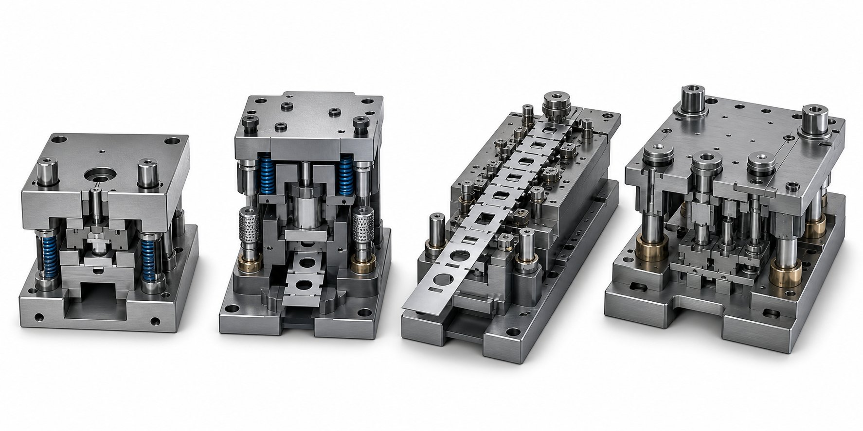
Selecting the wrong die type for a production run is one of the most expensive mistakes a tooling engineer can make. A die that is over-engineered wastes capital; one that is under-engineered bottlenecks throughput or produces scrap. Four primary configurations cover the vast majority of sheet metal stamping applications: single-station, compound, progressive, and transfer. Each operates on a different principle of how work is organized within the press stroke, and each fits a specific window of part complexity, volume, and budget.
Single-Station and Compound Dies
A single-station die performs exactly one operation per press stroke - a single cut, a single bend, or a single draw. Think of it as a dedicated punching die that does one job and does it well. You load a blank or strip, the press cycles, and you get one feature added to the part. Need three features? You run the part through three separate dies on three separate setups.
This simplicity is actually an advantage in the right context. Single-station dies are inexpensive to design and build, easy to troubleshoot, and fast to set up. They excel in low-volume production, prototyping, or situations where part geometry is straightforward enough that one operation completes the part - a simple blanking die cutting circular discs from strip stock, for instance.
Compound dies raise the capability by performing multiple cutting operations in a single stroke. A typical compound die might blank the outer profile and pierce internal holes simultaneously, producing a finished flat part in one hit. The punch press dies in a compound setup share a common shut height, so every feature aligns perfectly relative to the others without the tolerance stack-up that comes from multiple setups.
Where do compound dies shine? Washers, gaskets, lamination stacks for electric motors, and any flat precision part where positional accuracy between features is critical. Because all cuts happen in one stroke, the risk of misalignment between operations is minimized, and scrap rates stay low. The trade-off is that compound dies handle cutting and limited coining well but are not designed for complex bending or deep drawing.
Progressive and Transfer Dies
When part complexity or volume climbs, progressive dies become the workhorse. A progressive die contains multiple stations arranged in sequence along the direction of strip feed. The coil stock advances through the die one pitch length per stroke, and each station performs a different operation - piercing, notching, forming, or trimming - until the finished part is cut free at the final station.
How do engineers determine station count and sequencing? It starts with the part geometry. Every feature that cannot be produced simultaneously with another (due to force conflicts, material flow interference, or geometric access) requires its own station. A simple bracket might need five or six stations. A complex electrical connector with multiple bend angles, lances, and coined features might require 15 or more. Researchers have proposed scoring systems that weigh station number, moment balancing, strip stability, and feed height to evaluate and rank competing strip layouts before committing to a final design.
Progressive dies deliver exceptional speed - often running at hundreds of strokes per minute - with consistent quality across millions of parts. They are the default choice in automotive, electronics, and appliance manufacturing wherever annual volumes justify the tooling investment. The forming die stations within a progressive tool can include bending, drawing, and embossing alongside cutting operations, making these tools remarkably versatile.
Transfer dies solve a different problem. Some parts are too large, too deep-drawn, or too geometrically complex to remain attached to a carrier strip. In a transfer die system, individual blanks or partially formed shells are mechanically transferred from one station to the next by a press and die automation mechanism - typically finger transfers or tri-axis servo units. Each station is essentially an independent die performing one operation, but the automated handling links them into a continuous production flow.
Transfer dies are common in automotive body panels, structural brackets, and appliance housings where part size exceeds what strip stock can practically carry. They offer more flexibility in part orientation between stations, and they accommodate deeper draws and more radical shape changes than a progressive setup allows. The trade-off is a slower cycle rate and higher operational complexity.
| Die Type | Operations per Stroke | Ideal Part Complexity | Typical Production Volume | Relative Tooling Cost |
|---|---|---|---|---|
| Single-Station | 1 | Simple (one feature) | Low to medium | Low |
| Compound | Multiple cutting ops | Flat parts, tight positional tolerances | Medium to high | Moderate |
| Progressive | One per station, multiple stations per stroke | Moderate to high (multi-feature, bendable) | High to very high | High |
| Transfer | One per station, part moved between stations | High (large, deep-drawn, complex 3D) | Medium to high | High to very high |
Matching die type to application is ultimately a balance of part geometry, annual volume, and budget. A simple forming die for a low-volume bracket does not need progressive tooling. Conversely, an electrical connector produced at 50 million units per year cannot be economically stamped on a single-station setup. Forming dies and transfer systems each occupy a niche defined by what the part demands and what the production economics support.
Understanding which configuration fits your project is the first strategic decision. The next layer of complexity lives inside the die itself - the individual components that make all of this precision possible.
Key Components and Die Set Configurations Explained
Every stamping die type discussed above - from a simple blanking tool to a 20-station progressive - is built from the same family of core press die components. Think of a die assembly the way you would think of a building: the foundation keeps everything aligned, the structural elements carry load, and the functional elements do the actual work. Knowing what each part does helps you specify tooling correctly and troubleshoot faster when something drifts out of tolerance.
Core Components of a Die Assembly
A stamping die splits into two halves. The upper half mounts to the press ram; the lower half bolts to the press bed. Between them, the sheet metal is shaped with every stroke. Here is how the main stamping die components break down by function:
- Die shoes (upper and lower plates) - The rigid steel or aluminum plates that form the foundation of the entire die assembly. All other components mount to these plates, and their flatness and parallelism determine overall tool accuracy.
- Punch holder (retainer) - A hardened plate or block secured to the upper die shoe that locates and retains individual punches in their correct positions.
- Punches - The cutting or forming tools that press into the sheet metal. Nose shapes range from round and oblong to fully custom profiles, depending on the feature being produced.
- Strippers - Spring-loaded plates that hold the strip flat against the die plate during the cut and then push it off the punches as the ram retracts. Without strippers, the material would lift with the punch and jam the tool.
- Die plate and die blocks - The lower working surface containing apertures (buttons) that provide the opposing cutting edge for each punch. Die blocks are hardened inserts pressed or bolted into the die plate for easy replacement when edges wear.
- Guide pins and bushings - Precision-ground posts and sleeves that align the upper and lower halves to within tenths of a thousandth of an inch on every stroke. Ball-bearing guide pins have become industry standard for their ease of separation and consistent preload characteristics.
- Back-up plates - Hardened plates placed behind punches or die blocks to distribute impact force and prevent the softer die shoe from deforming over millions of cycles.
- Springs (mechanical or nitrogen gas) - Provide the controlled force that drives strippers, pressure pads, and blank holders through their working range.
Each of these parts works as a system. A worn guide bushing throws punch-to-die alignment off, which increases burr height, which accelerates die block wear - a cascade that starts with one neglected component.
Die Set Configurations and Selection Criteria
The die set - meaning the die shoes plus their guide pin arrangement - is the structural backbone you select before designing any working components. Four standard layouts cover most applications:
| Configuration | Guide Pin Placement | Best Application | Key Advantage |
|---|---|---|---|
| Back-post | Two posts at the rear of the die set | Progressive dies with front or side strip feeding | Unobstructed operator access from three sides |
| Center-post | Two posts centered on opposite sides | Symmetrical blanking and moderate-load operations | Balanced guidance with good access from front and rear |
| Diagonal-post | Two posts at opposite diagonal corners | Off-center loading or asymmetric part geometry | Resists moment loads that would twist a back-post set |
| Four-post | Four posts, one at each corner | Heavy blanking, large die plates, high tonnage | Maximum rigidity and resistance to deflection |
How do you choose? Start with feed direction and operator access - back-post die sets dominate progressive tooling precisely because the strip enters from the side or front without interference. If your application generates high side loads or the part geometry places cutting forces off-center, a diagonal-post layout counteracts the twisting moment that would wear a two-post set unevenly. Four-post die sets are the default for large, heavy blanking operations where any deflection in the die plate would translate directly into inconsistent cut quality.
Standard die set dimensions are cataloged by suppliers in increments that correspond to common press bed sizes and shut heights. When specifying a die set, you need to confirm that the combined stack height of the closed die assembly - shoes, plates, and tooling - fits within the press shut height, and that the footprint clears the bolster area with room for clamps. Getting this wrong means the die physically will not run in the intended press, an expensive oversight that is entirely avoidable at the design stage.
With the structural foundation and functional components mapped out, the real engineering challenge begins: designing the working geometry that turns flat strip into a finished part.
The Stamping Die Design Process From Concept to CAD
A die assembly is only as good as the engineering behind it. You can select the perfect die type, source premium tool steels, and hire expert machinists - but if the design logic is flawed, the tool will fight you through every tryout cycle. The design phase is where stamping tool and die engineers translate a 2D part drawing into a fully validated 3D tooling concept, and it follows a disciplined sequence that balances forming physics, material behavior, and production economics.
From Part Geometry to Strip Layout
Every custom metal stamping die project starts with the finished part geometry. Engineers study the 3D model or drawing, identify each feature - holes, bends, draws, embosses - and determine which operations are needed and in what order they must occur. A deep-drawn cup, for example, cannot be pierced before drawing because the hole would distort during forming. Sequencing mistakes like this are expensive to fix once steel is cut.
For progressive tooling, this forming sequence translates directly into a strip layout - a map showing how raw coil stock moves through the die station by station. The layout defines strip width, pitch (the distance between successive parts), carrier type, and scrap locations. Material utilization is a major cost driver here. A strip layout that wastes 40% of incoming coil stock might be redesigned with a different nesting angle, narrower carriers, or staggered part orientation to push utilization above 70%.
Die clearance - the gap between punch and die cutting edges - is another critical calculation at this stage. It is expressed as a percentage of material thickness and varies by material type. Mild steel typically requires 5-10% clearance per side, while aluminum may need 8-12%, and stainless steel often demands tighter values around 3-5% to control burr formation. Get clearance wrong and you will see excessive burrs, premature edge wear, or slug pulling from the first stroke.
CAD-CAM Workflow and CAE Simulation
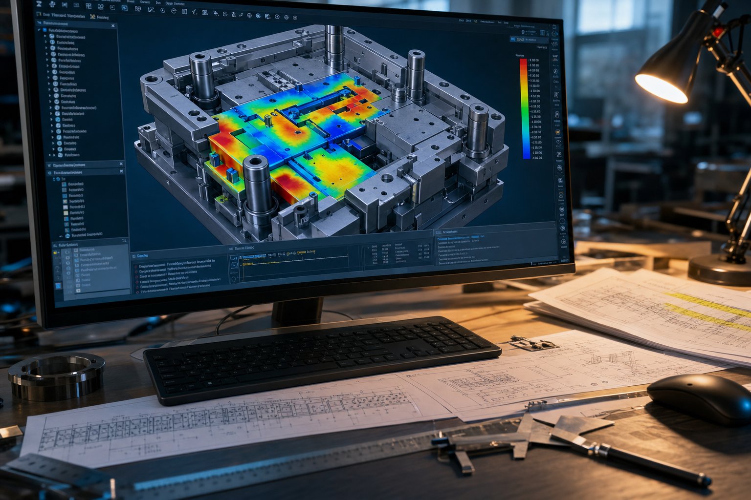
With the process layout defined on paper, engineers build the full die and tooling assembly in 3D CAD - modeling every punch profile, die block aperture, stripper plate, and guide component. This digital twin becomes the master reference for all downstream machining programs and inspection data.
Here is where modern custom die development diverges sharply from traditional methods. Rather than committing immediately to fabrication, engineers feed the CAD geometry into CAE (Computer-Aided Engineering) simulation software. Using finite element analysis, the software models how sheet metal will behave under forming forces - predicting springback deformation, thinning risk, wrinkling tendencies, and strain distribution across the part surface. Forming Limit Diagrams (FLDs) highlight red zones where cracking is likely and blue zones where compression may cause wrinkles.
Simulation results drive iterative design changes before any physical tooling exists. An engineer might adjust a draw radius, modify blank holder pressure, add a draw bead, or reshape the blank contour - all digitally. Manufacturers that integrate CAE early in the workflow typically reduce tryout iterations by 30-50%, cutting weeks off project timelines and thousands off modification budgets.
Press tonnage estimation also happens during this phase. Engineers calculate the force required for each operation - blanking tonnage based on shear length, material thickness, and shear strength; forming tonnage based on bend length and material properties - then sum them with a safety factor to select the correct press. Undersizing the press risks stalling mid-stroke; oversizing wastes capital and floor space. Precision die and stamping outcomes depend heavily on this match between calculated load and available machine capacity.
The complete tool die design workflow follows a predictable sequence from initial concept to production release:
- Feasibility study - evaluate part geometry, material formability, and preliminary process concept.
- Process and strip layout - define forming sequence, station assignments, pitch, and carrier design.
- Die clearance and tonnage calculations - establish critical parameters for cutting and forming.
- 3D CAD die design - model all working components, die sets, and auxiliary systems.
- CAE forming simulation - validate material flow, predict defects, and iterate geometry.
- Design review and optimization - incorporate simulation feedback, finalize tolerances, confirm press fit.
- CAM programming - generate tool paths for CNC milling, wire EDM, and grinding operations.
- Final design release - issue approved drawings and data packages for fabrication.
Each stage feeds the next, and skipping steps - particularly simulation - almost always costs more in rework than it saves in schedule. The die tooling development process is fundamentally front-loaded: invest engineering hours early to avoid expensive surprises on the shop floor later.
Of course, even the most refined CAD model is only a digital promise. Turning that promise into hardened steel tooling that produces conforming parts requires a fabrication process with its own set of precision demands.
Material Selection and Heat Treatment for Die Longevity
A perfectly designed die that is built from the wrong steel will fail early - cracking under impact, galling against the workpiece, or wearing past tolerance in a fraction of its expected life. Material selection is the link between the digital design and real-world durability, yet it rarely gets the attention it deserves during project planning. The steel grade you choose for punches, die blocks, and form die inserts directly determines how many parts you can run between sharpening cycles, how resistant the tool is to chipping, and ultimately how much each stamped part costs.
Tool Steel Grades for Die Components
Steel stamping dies rely on a handful of proven tool steel families, each optimized for a different balance of hardness, toughness, and wear resistance. These three properties exist in tension: push hardness higher and you gain wear resistance but lose toughness (resistance to cracking). Here is how the most common grades stack up.
D2 is the default cold-work steel for blanking and cutting operations. Its high carbon (1.4-1.6%) and chromium (11-13%) content delivers exceptional abrasive wear resistance at a working hardness of 54-61 HRC. D2 is widely used in sheet metal dies where the primary failure mode is gradual edge wear rather than sudden impact. The trade-off is lower toughness - D2 punches can chip or fracture if subjected to severe shock loads.
A2 offers a middle ground. With moderate chromium (4.75-5.5%) and slightly less carbon than D2, it achieves 57-62 HRC while maintaining better toughness. A2 is a common choice for trimming dies, long punches, and precision tools where both wear life and resistance to chipping matter.
S7 sits at the opposite end of the spectrum from D2. This shock-resistant grade reaches only 48-58 HRC but delivers outstanding impact resistance. You will find S7 in metal forming dies that perform heavy bending, coining, or cold forming - anywhere the die absorbs repeated high-energy blows that would crack a harder grade.
M2 is a high-speed steel containing tungsten and molybdenum, capable of maintaining hardness at elevated temperatures. It suits punching operations where frictional heat builds up at high stroke rates, and it is often specified for small-diameter piercing punches in progressive tooling.
Carbide inserts (typically tungsten carbide) deliver hardness values above 85 HRA - far beyond any tool steel - and are used for wear-critical stations in high-volume progressive dies. A sheet metal die running abrasive materials like stainless steel or high-strength dual-phase grades may use carbide-tipped punches to push tool life from hundreds of thousands into millions of hits.
Cr12MoV deserves mention as the dominant die steel in Asian die shops. Functionally equivalent to D2 (same alloy family, similar chromium content), Cr12MoV is widely specified in China and Southeast Asia for blanking and trimming applications. Its broad availability and lower cost in Asian supply chains make it the go-to choice for export tooling destined for mid- to high-volume production.
| Grade | Hardness Range (HRC) | Primary Use in Die | Relative Cost Tier |
|---|---|---|---|
| D2 | 54 - 61 | Blanking punches, trim steels, cutting edges | Moderate |
| A2 | 57 - 62 | Trim dies, long punches, precision tools | Moderate |
| S7 | 48 - 58 | Bending, cold forming, shock-loaded stations | Moderate |
| M2 | 60 - 65 | High-speed piercing punches, small-diameter tools | Moderate-High |
| Cr12MoV | 58 - 62 | Blanking and trimming (Asian die shops) | Low-Moderate |
| Tungsten Carbide | 85+ HRA | Wear-critical inserts, high-volume stations | High |
Heat Treatment and Surface Engineering
Raw tool steel is only a starting point. Without proper heat treatment, even D2 or M2 cannot deliver their rated performance. The core sequence - hardening, tempering, and optional cryogenic treatment - transforms the steel's microstructure into the high-hardness, stress-relieved condition required for production service.
Hardening involves heating the steel into its austenite region and quenching (air-hardening for D2, A2, and S7) to form martensite. Tempering follows immediately: one or more heating cycles at moderate temperatures relieve internal stresses and adjust the hardness-toughness balance. Higher-alloy grades like D2 and M2 require multiple tempering cycles because significant retained austenite remains after the first temper. Skipping the second temper leaves brittle, untempered martensite in the microstructure - a common root cause of early die cracking.
Cryogenic treatment adds another dimension. By slowly cooling hardened steel to temperatures below -150 degrees C and holding for an extended period, retained austenite converts more completely to martensite while fine secondary carbides precipitate uniformly through the matrix. The result is improved wear resistance and dimensional stability. Research published in the Journal of Materials Processing Technology confirms that deep cryogenic treatment enhances the mechanical properties of tool steels beyond what standard cold treatment achieves, with the most significant improvement occurring when treatment is applied between quenching and tempering.
Surface engineering extends die life further still, particularly for punches working against abrasive or high-strength sheet metal. The most common approaches include:
- Nitriding (gas or plasma ion) - diffuses nitrogen into the tool surface, creating a hard case without the distortion risk of high-temperature processes. Ion nitriding is faster and produces a thinner brittle white layer than gas nitriding.
- PVD coatings (TiN, TiCN, TiAlN, CrN) - physical vapor deposition applies thin, extremely hard films at relatively low temperatures (below 500 degrees C), preserving substrate hardness. PVD-coated cutting steels show dramatically reduced galling and more uniform cut edges compared to uncoated tools, even after hundreds of thousands of strokes.
- TD (Thermal Diffusion / Toyota Diffusion) process - a CVD-family treatment that forms vanadium carbide or chromium carbide layers at the surface. The resulting coating is metallurgically bonded and extremely hard (3200-3800 HV), making it effective for punches in high-abrasion stamping applications. The trade-off is a processing temperature around 1000 degrees C, which may soften the substrate and require rehardening.
A practical rule emerges from these options: always harden and temper the substrate first, then apply the surface treatment. Coating over a soft substrate invites plastic deformation beneath the coating layer, leading to cracking and premature failure. Studies on automotive stamping tooling show that combining ion nitriding with a PVD coating on properly hardened D2 produced more than 1.2 million parts before requiring service - compared to just 50,000 parts for chrome-plated tooling on the same application.
The upfront cost of premium steel grades and advanced coatings is real, but it pales against the accumulated cost of unplanned downtime, frequent sharpening, and scrapped parts from worn tooling. Selecting the right material and treatment combination is an investment in process stability - and it only pays off if the fabrication process that follows converts that material into accurate, well-finished tooling geometry.
Die Fabrication From CNC Machining to Trial Runs
Premium tool steel, optimized heat treatment, and a simulation-validated CAD model all converge at one point: the die manufacturing floor. This is where digital geometry becomes hardened tooling capable of producing conforming parts at speed. Each machine in the fabrication sequence addresses a specific class of geometry or tolerance requirement, and understanding their roles explains why machining dies is both an art and a precision science.
Machining and EDM in Die Fabrication
CNC milling handles the bulk of material removal. A 3-axis machining center roughs and semi-finishes die shoes, back-up plates, and simple punch profiles - anything with straightforward pocket or contour geometry. When surfaces become sculptured or access angles tighten, the work moves to 5-axis mills that can approach complex form die surfaces from virtually any direction without reclamping. Five-axis capability is especially valuable for progressive die blocks where multiple station profiles must maintain tight positional relationships across the full length of the plate.
Sounds simple so far? Here is where it gets more demanding. Many die features - tight-tolerance apertures, intricate punch profiles, and sharp internal corners - cannot be reached by a rotating cutter at all. That is where EDM (electrical discharge machining) takes over.
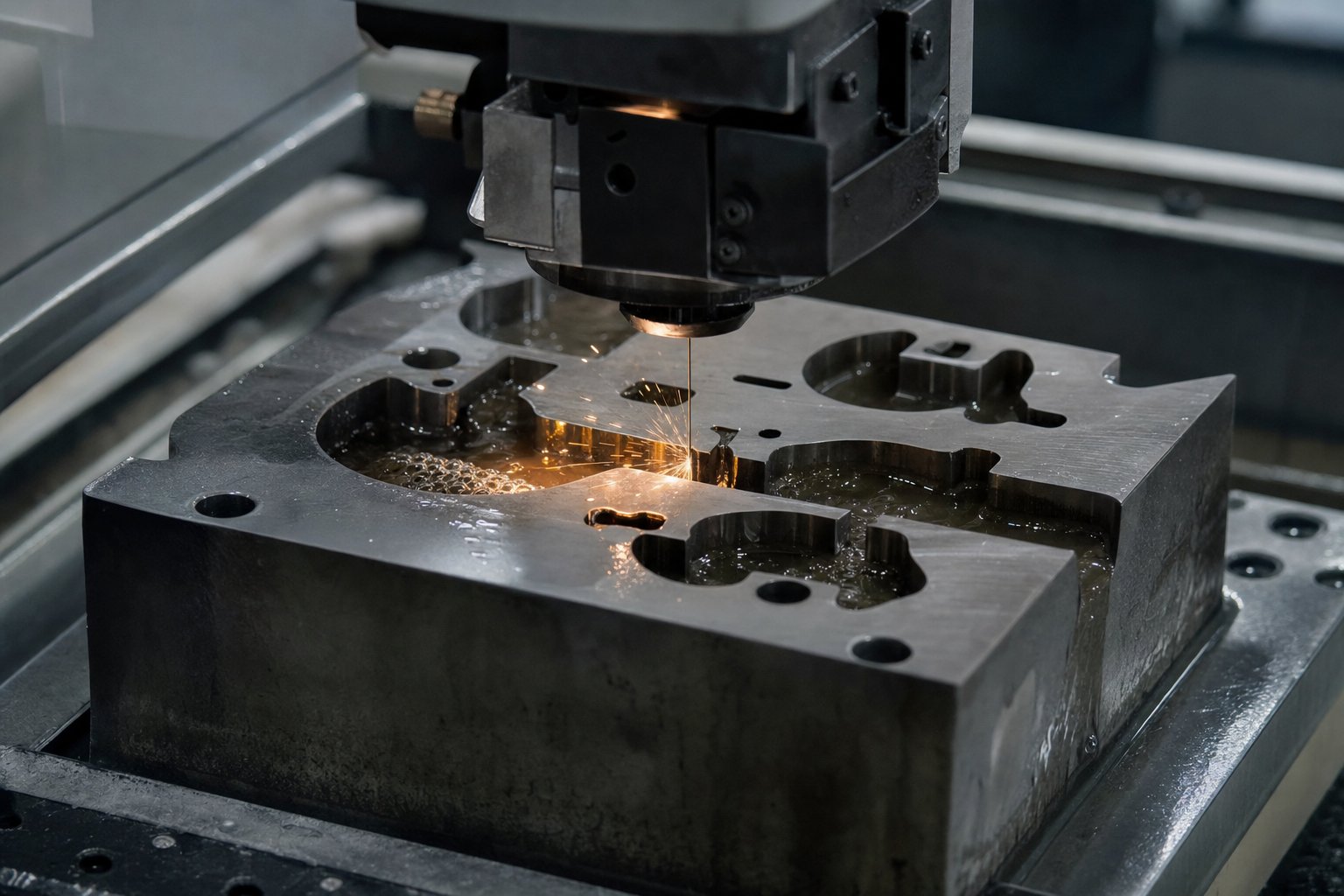
Wire EDM uses a thin brass or zinc-coated wire electrode to cut 2D profiles and angled contours through fully hardened die blocks. Sparks discharge along the wire, eroding material without mechanical force or heat distortion. The process is ideal for die maker tools like blanking apertures, complex punch cross-sections, and tight-clearance die buttons - features where surface finish and dimensional accuracy must hold within microns. Modern 5-axis wire EDM centers can even produce tapered or variable-angle cuts by offsetting the upper and lower wire guides independently.
Sinker EDM (also called ram or cavity EDM) addresses 3D cavity features. A pre-machined copper or graphite electrode is plunged into the workpiece, and spark erosion transfers the electrode's complex shape into the die steel. This technique is indispensable for die tools that require relief pockets, emboss cavities, or coined lettering - geometry where no rotating cutter could maintain the required detail. Because EDM imposes virtually no mechanical stress on the workpiece, thin sections and fine features survive intact without distortion, a critical advantage when machining dies from pre-hardened tool steels like D2 or carbide inserts.
After milling and EDM, surface grinding delivers the flatness that die assemblies demand. Punch faces, die plates, back-up plates, and die shoes are ground to within 0.005 mm flatness so the upper and lower halves mate without rocking or uneven pressure distribution. Jig grinding takes this precision further for critical bore locations - guide pin holes, dowel positions, and die button pockets - where positional accuracy drives punch-to-die alignment across the entire tool.
Coordinate measurement machines (CMMs) verify these critical dimensions at multiple stages during fabrication, not only at the end. A machine die block might be checked after rough milling, rechecked after heat treatment (to quantify any distortion), and verified again after finish grinding. This in-process approach catches drift before it propagates into assemblies that are expensive to rework.
Die Tryout and Validation
A fully assembled die is not production-ready until it proves itself on a tryout press. The tryout phase bridges the gap between theoretical design and real-world performance - and even the best-simulated manufacturing die almost always requires some adjustment during initial trials.
Imagine loading the completed tool into a dedicated tryout press, feeding the first strip of material, and cycling the press for the initial hit. That first part off the die tells a story: are the dimensions within GD&T callouts? Is the trim edge clean or burred? Does the formed geometry spring back beyond tolerance? Tryout technicians read these clues and translate them into corrective actions - spotting high points with bluing compound, shimming form sections, adjusting nitrogen spring preloads, or re-grinding cutting edges for tighter clearance.
This iterative loop - stamp, measure, adjust, re-stamp - continues until parts consistently meet print specifications. For complex progressive tooling, the process may run through multiple rounds over several days. Each iteration narrows the gap between actual and nominal dimensions.
Final validation relies on formal inspection protocols. CMM-based inspection captures dimensional data for every critical feature against the GD&T scheme. Optical or laser scanning generates full-surface deviation maps that reveal areas of springback or thinning invisible to point-based measurement. Statistical Process Capability (SPC) data from a short production run - typically 30 to 50 consecutive parts - confirms that the die produces stable, repeatable output with Cpk values meeting customer requirements (often 1.33 or higher for critical characteristics).
Only after this evidence package is complete does the die receive production release sign-off. The full fabrication-to-validation sequence follows a disciplined path:
- CNC rough machining of die shoes, plates, and blocks from pre-hardened or annealed blanks.
- Heat treatment (if machined in annealed state) followed by stress relief and dimensional verification.
- CNC finish milling of form surfaces, pockets, and profiles.
- Wire EDM of cutting apertures, complex contours, and tight-tolerance features.
- Sinker EDM for 3D cavity details, emboss forms, and coined features.
- Surface grinding of mating faces, punch tips, and die plates to final flatness.
- Jig grinding and bore finishing for guide pin holes and critical locating features.
- CMM inspection and dimensional verification of all critical features against design intent.
- Die assembly - fitting punches, strippers, springs, guides, and fasteners into the die set.
- Initial tryout on a dedicated press with sample material to produce first-off parts.
- Measurement, spotting, and iterative adjustment until parts meet GD&T requirements.
- SPC validation run and final sign-off with documented inspection data package.
Each step in this sequence depends on the quality of the one before it. A die block ground out of flat will never produce consistent parts regardless of how many tryout iterations you attempt. That is why die manufacturing demands both the right equipment and the discipline to verify at every transition point - not just at the end.
A signed-off die is ready for production, but production is where the real endurance test begins. Millions of press cycles subject every component to cumulative wear, fatigue, and the occasional unexpected overload - challenges that only a structured maintenance program can manage.
Die Maintenance and Troubleshooting Stamping Defects
A die that passes tryout validation with flying colors can still become a production liability within weeks if no one manages its wear. Every press stroke applies tonnage to hardened cutting edges, compresses springs, and cycles guide components through their travel. Multiply that by hundreds of strokes per minute, and you begin to see why even the best metal punches and dies degrade over time. The difference between a shop that runs smoothly and one that fights constant quality fires comes down to one thing: whether the team practices true preventive maintenance or just repairs what breaks.
Preventive Maintenance and Lifespan Management
There is a meaningful distinction between die maintenance and die repair. As MetalForming Magazine frames it, repair is the act of restoring something broken back to working condition - firefighting. Maintenance is the process of preserving functionality before failure occurs. Shops that blur these two activities often find their "maintenance" team spending 80% of its time chasing emergency breakdowns, never getting ahead of the curve.
A structured preventive maintenance (PM) program revolves around several recurring tasks, each tied to measurable intervals:
- Sharpening cutting sections - Die punch edges and die buttons wear progressively with each stroke, producing gradually increasing burr height on stamped parts. Scheduling sharpening based on measured burr height (typically before it exceeds 10% of material thickness) keeps cut quality consistent. When grinding, use an appropriate wheel that breaks down freely rather than loading up and burning the tool steel. Flood coolant prevents heat buildup that can soften or crack hardened sections like D2 or M2, as The Fabricator notes.
- Spring replacement cycles - Mechanical springs fatigue and lose force over time, while nitrogen gas springs can leak pressure. Replace springs before they reach their rated cycle life rather than waiting for breakage. A spring that fractures mid-run can damage surrounding die components and produce a cascade of scrap parts.
- Lubrication - Guide pins, cam surfaces, wear plates, and lifter rails all require periodic lubrication. Dry surfaces gall and score, eventually degrading alignment precision. Follow the die builder's lubrication map and verify coverage during every PM cycle.
- Wear measurement - Use calibrated pins, bore gauges, or CMM spot checks to quantify wear on critical surfaces. Guide bushing clearance, die button bore diameter, and form steel radii all drift over time. Documenting these measurements creates a wear-rate profile that predicts when components will exceed tolerance.
How do you know when to perform each task? Stroke counters mounted on the press or integrated into the die provide the answer. Every time the ram cycles, the counter increments. Pair that count with a die maintenance log - a running record of what was done, what was measured, and what was replaced - and you shift from guessing to data-based scheduling. This approach mirrors what industry professionals call predictive maintenance (PdM), where real performance data determines when intervention should happen rather than relying on fixed calendar intervals alone.
One practical caution: avoid both over-maintenance and under-maintenance. Sharpening punches and dies every 100,000 strokes by rote - even when burr height is still acceptable - wastes material and shortens total tool life. Conversely, stretching intervals too far risks catastrophic failures that turn a simple sharpening job into an expensive die repair. The maintenance log resolves this tension by showing actual wear rates for each specific tool running each specific material.
Troubleshooting Common Stamping Defects
Even with solid PM practices, defects occasionally appear. The key is diagnosing root causes quickly rather than chasing symptoms. When you see a quality issue on a stamped part, it usually traces back to one of four common failure modes in the sheet metal punch and die system. Here is a breakdown of each, along with corrective actions:
| Defect | Root Cause | Corrective Action | Prevention Strategy |
|---|---|---|---|
| Burrs (raised sharp edges on cut perimeter) | Insufficient punch-to-die clearance, dull cutting edges, or misalignment between punch and button | Sharpen or replace worn die punches and buttons; verify and correct clearance per material spec (typically 5-10% of thickness per side for mild steel) | Track burr height at regular intervals; sharpen on schedule before limits are reached; maintain guide pin fit to prevent alignment drift |
| Springback (part returns toward original shape after forming) | Under-compensation in die geometry; high-strength material with large elastic recovery; insufficient bottoming or coining force | Overbend the form section to compensate; add restrike stations; increase tonnage or add coining at bend apex | Use CAE simulation to predict springback and build compensation into the die design; validate with first-off measurement and adjust before production release |
| Wrinkling (waves or buckles in drawn or formed areas) | Insufficient blank holder pressure; inadequate draw bead restraint; excess unsupported material in compression zones | Increase blank holder force; add or modify draw beads; adjust blank size to reduce excess material flow | Optimize blank holder pressure and draw bead geometry during die design using forming simulation; monitor nitrogen spring pressure during production |
| Galling (material transfer from workpiece to tool surface, causing scoring) | Poor lubrication, coating failure on die surface, high friction between tool and workpiece (common with stainless steel and aluminum) | Re-polish affected tool surfaces; restore or reapply PVD coating; improve lubricant type or application coverage | Specify PVD-coated or TD-treated punches for galling-prone materials; verify lubricant delivery system function at every die setup; keep sheet metal punch dies clean of debris and buildup |
Notice the pattern: most defects trace to either wear (burrs, galling) or design compensation issues (springback, wrinkling). Wear-related defects respond to maintenance actions - sharpening, recoating, lubrication. Compensation-related defects often require engineering changes to the die geometry itself.
When a press die punch shows galling damage, for example, simply polishing the surface provides a temporary fix. The lasting solution involves upgrading the surface treatment or switching to a material-lubricant combination that prevents adhesive transfer in the first place. Troubleshooting is most effective when it addresses root causes rather than symptoms.
Refurbishment economics also deserve attention. A worn die does not always need to be replaced. Re-grinding cutting edges, re-coating form steels, replacing worn guide bushings, and resurfacing die shoes can restore a tool to near-original performance at a fraction of new-build cost - typically 15-30% of replacement value. The decision point is straightforward: if the die structure (shoes, plates, mounting geometry) remains sound and the required modifications are limited to wear surfaces, refurbishment makes financial sense. If core geometry has shifted, plates are cracked, or the part design has changed significantly, building new tooling is the more reliable path.
Keeping punches and dies in production-ready condition is ultimately a cost management strategy. Every hour of unplanned downtime, every batch of scrapped parts, and every emergency repair carries hidden expenses - expedited shipping, idle operators, and missed delivery windows - that far exceed the cost of disciplined scheduled maintenance. The shops that internalize this reality build maintenance into their production planning from day one, not as an afterthought when defects reach the customer.
Knowing how to maintain a die is one half of the equation. The other half is ensuring you specified and sourced the right tool in the first place - a process that begins well before any purchase order is issued.

How to Specify and Source a Custom Stamping Die
Understanding die types, materials, and maintenance is valuable - but none of it matters if you cannot translate that knowledge into a clear specification that gets the right tool built. The gap between "I know what a progressive die is" and "I have a validated die running production parts" is bridged by two practical steps: preparing an RFQ that gives stamping die manufacturers exactly what they need to quote accurately, and evaluating suppliers against criteria that predict long-term success rather than just lowest initial price.
How to Prepare an Effective Stamping Die RFQ
Imagine sending a die shop a part drawing with no material callout, no volume forecast, and tolerances copied from an unrelated project. What comes back? A quote full of assumptions - or worse, a competitive-looking number based on the cheapest interpretation of your vague requirements. Either way, you are comparing apples to guesswork when multiple bids land on your desk.
A well-structured RFQ for custom metal stamping dies eliminates this ambiguity. It gives every quoting supplier the same technical baseline so their responses reflect real capability differences rather than different interpretations of incomplete information. Drawing from established RFQ best practices, the core principle applies equally to stamping tooling: if the technical package is incomplete, the supplier has to guess, and those guesses affect price, lead time, and whether the quoted approach actually suits your part.
What should engineers and sourcing managers include? Here is the essential package for a stamping die RFQ:
- Part drawing with full GD&T - Include both a 3D CAD model (STEP format preferred) and a 2D PDF drawing with tolerances, datum references, and critical-to-function features clearly identified. The 3D model lets the die shop evaluate formability; the 2D drawing defines dimensional intent.
- Material specification - State the exact alloy, temper, thickness, and any applicable standard. "1.0 mm stainless steel" is not specific enough. "SUS304, 2B finish, 1.0 mm +/-0.05 mm per ASTM A240" eliminates guesswork about grade and condition.
- Annual volume forecast - Provide expected quantities in tiers: initial pilot run, first-year volume, and steady-state annual demand. Volume drives the die type recommendation (compound vs. progressive), material grade selection for die components, and whether carbide inserts are justified.
- Target die life - Express this in total strokes before major refurbishment. A die expected to produce 500,000 parts total requires very different construction than one targeting 10 million. This single number influences tool steel grade, surface treatment, and the overall cost tier of the project.
- Quality requirements - Specify inspection expectations (CMM dimensional report, SPC capability study, first-article inspection protocol), applicable quality system standards (ISO 9001, IATF 16949), and acceptance criteria for critical dimensions (Cpk targets).
- Secondary operations - If parts require tapping, welding, plating, or heat treatment after stamping, include these in the RFQ scope. Suppliers who manage secondary processes in-house can offer better lead times and tighter process control than those who subcontract every additional step.
Part complexity is the single biggest driver of die type selection and cost. A flat bracket with three holes might need only a compound die costing a few thousand dollars. A multi-bend connector with formed tabs, coined features, and tight positional tolerances could require a 12-station progressive tool at 10 to 20 times that investment. When your RFQ clearly communicates geometric complexity, volume, and life expectancy, capable die manufacturing companies can recommend the right approach rather than defaulting to what they assume you can afford.
One practical tip: send the identical file set, same revision level, and same assumptions to every supplier on your bid list. As manufacturing RFQ research confirms, inconsistent packages mean price differences reflect different assumptions rather than real differences in capability - making meaningful quote comparisons impossible.
Evaluating Stamping Die Suppliers
Price is easy to compare. Capability is harder - and far more predictive of whether you will get a working die on schedule or spend months in painful tryout loops chasing problems that better engineering would have prevented. The best stamping dies manufacturer candidates distinguish themselves not by being cheapest, but by demonstrating end-to-end process control from feasibility through validated production parts.
When evaluating a die shop, look for these capability checkpoints:
- In-house CAE simulation - Can the supplier run forming simulations (springback prediction, thinning analysis, wrinkle maps) before cutting steel? Shops with this capability catch design issues digitally, reducing physical tryout iterations and compressing timelines.
- Machining equipment range - A capable die manufacturer needs CNC milling (3-axis through 5-axis), wire EDM, sinker EDM, surface grinding, and jig grinding. If any of these are outsourced, lead times extend and accountability fragments.
- Tryout press availability - Does the supplier own dedicated tryout presses matching the tonnage range of your production press? In-house tryout means faster iteration cycles and direct feedback between the engineers who designed the die and the technicians running it.
- Inspection capacity - Look for CMM equipment, optical or laser scanning for surface deviation mapping, and the ability to produce formal dimensional reports and SPC data that satisfy your quality system requirements.
- Post-delivery support - Dies need maintenance, spare parts, and occasional engineering changes throughout their production life. Suppliers who offer ongoing technical support, spare component inventories, and modification services are partners - not just vendors.
- Design for Manufacturability (DFM) feedback - The best die manufacturers do not simply build what you draw. They review your part geometry and suggest modifications that improve formability, reduce tooling complexity, or extend die life. This feedback loop, according to industry selection guides, can save significant cost and time before tooling design even begins.
- Quality certifications - ISO 9001 is the baseline. If your parts serve automotive applications, IATF 16949 certification signals a supplier with process discipline capable of meeting OEM expectations.
How do you assess these factors without visiting every shop? Start by requesting a capability overview with your RFQ response. Ask for equipment lists, example inspection reports from similar projects, and references from customers in your industry. A supplier confident in their process will share this openly.
As a concrete example, YICHEN illustrates what a full-service workflow looks like in practice - covering feasibility analysis, CAE-driven die design, precision CNC and EDM machining, in-house tryout with dedicated presses, and CMM inspection with documented validation packages. For engineers researching metal stamping dies for sale or sourcing managers building a custom metal punch die program, this type of integrated supplier eliminates the coordination burden of managing separate design houses, die shops, and inspection labs.
A final thought on supplier evaluation: the cheapest quote often reflects what has been left out, not what has been optimized. A die manufacturer who includes simulation, iterative tryout, and SPC validation in their price is accounting for the real cost of delivering a working tool. One who quotes only machining hours may look attractive on paper but will generate change orders once the die hits the press and parts do not conform. Evaluate total project cost - including timeline risk, rework probability, and ongoing support - rather than line-item tooling price alone.
The quality of your RFQ determines the quality of the quotes you receive. Invest the engineering time upfront to build a complete technical package, and you will spend far less time later arbitrating misunderstandings between what you needed and what the supplier assumed.
With a well-prepared specification and a capable supplier identified, the remaining question is strategic: how do you match die investment level to your production stage and long-term volume trajectory?
Choosing the Right Stamping Die Strategy for Your Project
You have the knowledge - die types, materials, design workflow, fabrication methods, maintenance practices, and supplier evaluation criteria. The question now is practical: given your specific part, your volume forecast, and your production timeline, what level of tooling investment actually makes sense? The answer depends on where you sit in the product lifecycle and how aggressively per-part cost needs to drop.
Matching Die Strategy to Production Goals
Four variables converge to determine the right stamping die set for any project: annual volume, part complexity, material type, and dimensional tolerance. Change any one of these, and the optimal die strategy shifts. A simple bracket stamped from mild steel at 500 pieces per year does not justify a progressive tool, regardless of how attractive the cycle time looks on paper. Conversely, a multi-feature connector destined for 5 million annual units cannot be produced economically on single-station tooling - the labor and handling costs per part would overwhelm any savings on tooling.
The cost-per-part perspective ties everything together. A progressive die with carbide inserts might cost $40,000 to $80,000 upfront, but running on a die stamping machine at 200 strokes per minute, it produces parts for fractions of a cent each in material and press time. That same part made on a compound die at lower speed - with manual loading and more handling - might carry a unit cost five to ten times higher. Over a multi-year production run, the higher tooling investment pays for itself many times over through reduced piece price and consistent quality.
Material choice amplifies this effect. Sheet metal stamping dies running abrasive high-strength steel or stainless need harder tool steels and surface coatings to maintain edge life. The added upfront cost of carbide inserts or TD-treated punches extends sharpening intervals from 50,000 hits to 500,000 or more - which means less downtime, fewer maintenance cycles, and more revenue-generating press hours across the die's lifespan. Tolerance requirements also matter: tighter specs demand more rigid press die set configurations (four-post die sets), finer machining, and longer tryout phases, all of which add cost but reduce scrap and rework downstream.
Moving From Research to Action
Where does your project sit right now? Here is a concise decision framework matched to production stage:
- Prototype stage - Part design is not finalized. Consider soft tooling (aluminum or mild steel dies rated for 1,000-5,000 hits) or skip stamping entirely in favor of laser cutting and CNC bending. The goal is design validation, not production efficiency. Committing to hardened metal stamping die sets at this point risks expensive rework when geometry changes.
- Pilot production (1,000-50,000 parts) - Design is stable but volumes do not yet justify progressive tooling. Single-station or compound dies built from standard tool steels (D2, A2) deliver good part quality at moderate tooling cost. These tools also serve as insurance: if the product does not reach projected volumes, your capital exposure stays manageable.
- High-volume production (100,000+ annually) - Progressive dies with carbide inserts, PVD-coated punches, and four-post die sets running on a dedicated die stamping press become the clear economic winner. The tooling cost is significant, but per-piece costs drop dramatically as the initial investment amortizes across large production runs. At this stage, integrated CAE simulation, thorough tryout, and SPC validation are not optional luxuries - they are cost-reduction tools that prevent expensive mid-production corrections.
A hydraulic press die setup serving heavy-gauge structural parts follows the same logic but at higher tonnage thresholds, where press capacity and die rigidity become the dominant selection criteria rather than cycle speed alone.
The engineering rigor you invest before cutting steel - simulation, strip layout optimization, material selection, and supplier qualification - determines whether your stamping die delivers predictable cost-per-part economics or becomes a recurring source of downtime, scrap, and missed deliveries across its entire production life.
If you are still evaluating concepts, revisit the design and simulation guidance earlier in this article. If your part drawing is finalized, your volumes are defined, and you are ready to move from research into production, the next step is a complete RFQ package sent to a qualified supplier who can manage the full workflow - feasibility assessment, die design with forming simulation, precision fabrication, and validated trial parts. Manufacturers at this stage can explore YICHEN's custom stamping die solutions for end-to-end support that bridges the gap between an approved part design and first good production parts, giving sourcing managers and tooling engineers a practical starting point for supplier engagement.
Stamping Die Mould FAQs
1. What is the difference between a stamping die and an injection mold?
A stamping die shapes solid sheet metal at room temperature using mechanical force from a press, while an injection mold receives molten polymer into a sealed cavity where it cools and solidifies. Stamping dies use punch-and-die clearance, strippers, and guide systems, whereas injection molds require cooling channels, gate systems, and ejection mechanisms. The simple rule: if the raw material stays solid throughout the process, it is stamping die territory.
2. How long does a stamping die mould last before it needs replacement?
Die life varies widely based on tool steel grade, surface treatment, material being stamped, and maintenance discipline. A standard D2 steel die running mild steel may produce 500,000 to 1 million parts before major refurbishment. Progressive dies with carbide inserts and PVD coatings can exceed 5 million strokes. Factors like scheduled sharpening, spring replacement, and lubrication directly extend or shorten usable lifespan. Stroke counters and maintenance logs help predict optimal service intervals.
3. What information should I include in a stamping die RFQ?
An effective RFQ package includes a 3D CAD model (STEP format) with a 2D GD&T drawing, exact material specification with alloy and temper, annual volume forecast in tiers, target die life in total strokes, quality requirements such as Cpk targets, and any secondary operations needed. Sending identical file sets to all bidding suppliers ensures quotes reflect real capability differences. Suppliers like YICHEN (yichen-group.com/stamping-die/) use this complete package to provide accurate feasibility assessments and tooling recommendations.
4. How do I choose between a progressive die and a transfer die?
Progressive dies are ideal when parts can remain attached to a carrier strip throughout forming, typically suited for small to medium parts with moderate complexity at very high volumes (millions per year). Transfer dies are better for large parts, deep draws, or complex 3D geometries that cannot stay on a strip. Transfer systems offer more flexibility in part orientation between stations but run at slower cycle rates. The decision ultimately depends on part size, draw depth, and whether strip-based feeding is geometrically feasible.
5. What causes burrs on stamped parts and how do you fix them?
Burrs form when punch-to-die clearance is insufficient, cutting edges become dull, or alignment drifts between punch and die button. The corrective action involves sharpening or replacing worn punches and buttons, then verifying clearance matches the material specification (typically 5-10% of thickness per side for mild steel). Prevention relies on tracking burr height at regular intervals using stroke counters, scheduling sharpening before limits are reached, and maintaining guide pin fit to prevent progressive alignment drift.


