


What Pneumatic Die Roll Out Racks Are and Why They Matter
Imagine storing a 5,000-pound stamping die on a standard pallet rack. You can get it up there with a forklift, sure. But what happens when you need it back down in a hurry during a die changeover? You're waiting for equipment, blocking aisles, and burning production minutes that add up fast.
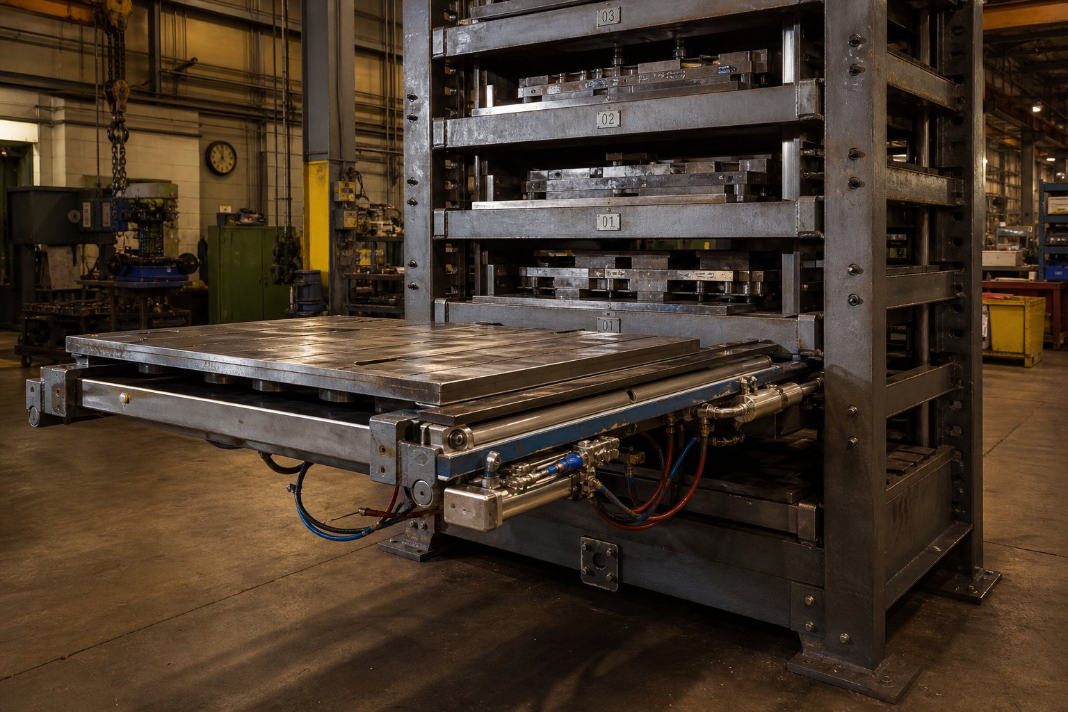
A pneumatic stamping die roll out rack solves this problem with a simple concept: individual shelves that slide outward on rails, assisted by compressed air cylinders, so operators can access heavy dies from the front without overhead cranes or forklift maneuvering. Each shelf works like a heavy-duty drawer. Air pressure does the hard work of extending shelves loaded with thousands of pounds, bringing the die to the operator rather than forcing the operator to reach into deep, fixed storage.
What Is a Pneumatic Stamping Die Roll Out Rack
At its core, this is a multi-level steel rack where each shelf rolls out independently on precision guide rails. Pneumatic cylinders, powered by the shop's existing compressed air supply, provide the force needed to extend shelves carrying dies that often weigh between 2,000 and 20,000 pounds. Once the shelf is fully extended, a crane or hoist lifts the die straight up for transport to the press. The rack itself eliminates the need for deep-reach forklift access and keeps floor space compact by stacking dies vertically.
Why Standard Storage Falls Short for Heavy Dies
Static shelving and conventional pallet racks create a fundamental accessibility problem for stamping operations. Fixed shelves force operators to work blind, reaching into rack bays with forklifts at awkward angles. Floor stacking wastes space and creates handling hazards. Crane-dependent static racks require overhead bridge cranes that many facilities either lack or share across multiple work cells.
Standard pallet racks and custom welded shelving store heavy dies adequately but fail at the point of retrieval. Without a way to bring the load to the operator, every die access event becomes a multi-step production delay involving equipment positioning, aisle clearing, and increased handling risk.
Roll-out die shelving closes that gap. As Cisco-Eagle notes, process storage where dies are frequently accessed demands dynamic rack options like roll-out systems that let operators store more tooling near their workstations and retrieve it with controlled, repeatable motions. The pneumatic version takes that concept further by eliminating the physical strain of pushing multi-ton shelves manually.
This article is not a product pitch. It is a technical guide designed to help tooling managers, plant engineers, and purchasing teams evaluate pneumatic roll out rack systems with clarity, starting with how the pneumatic mechanism actually works.
How Pneumatic Assist Mechanisms Work Inside Roll Out Racks
You know the shelf extends. You know compressed air powers it. But what actually happens between the moment an operator flips a valve and the moment a 6,000-pound loaded shelf glides outward? The engineering behind pneumatic assistance in die roll out racks is straightforward once you break it into its core principles: pressure, force multiplication, and controlled linear motion.
Air Cylinder Operation and Force Multiplication
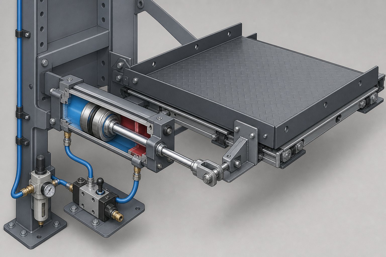
A pneumatic cylinder converts compressed air energy into linear motion. When air enters one side of the cylinder, it creates a pressure differential across the piston face, pushing the piston rod outward. That rod connects to the roll out shelf through a mechanical linkage, translating air pressure into the horizontal force needed to extend a loaded drawer.
Most pneumatic stamping die roll out rack systems use double-acting air cylinders, meaning compressed air actively drives the piston in both directions. Air supplied to the extend port pushes the shelf out; air supplied to the retract port pulls it back. This gives operators precise control over shelf movement in both directions without relying on spring return mechanisms that can wear out under heavy loads.
Single-acting cylinders, which use air pressure in one direction and a spring for the return stroke, occasionally appear in lighter-duty configurations. They cost less and consume less air, but the spring occupies internal space and adds a potential failure point. For shelves loaded with dies exceeding 3,000 pounds, double-acting cylinders are the standard choice because they deliver consistent force output regardless of direction.
The force multiplication principle is simple physics. Cylinder output force equals the air supply pressure multiplied by the piston's cross-sectional area. A 4-inch bore cylinder operating at 100 PSI generates roughly 1,256 pounds of extending force. Pair two cylinders per shelf, and you have over 2,500 pounds of push force available, more than enough to overcome the rolling friction of a properly loaded shelf on precision bearings. This is how a pneumatic roll out shelf's air pressure requirements translate directly into real-world pushing power.
Typical shop air systems supply between 80 and 120 PSI. Rack manufacturers design their cylinder bore sizes so that normal operating pressure in this range produces the force needed for the rated shelf capacity. Higher capacity racks simply use larger bore cylinders or additional cylinders per shelf rather than demanding exotic air pressures.
Key Mechanical Components in Pneumatic Roll Out Systems
The pneumatic assist mechanism is only one piece of a larger system. Several components work together to convert air pressure into smooth, safe shelf extension:
- Air cylinders - Double-acting cylinders (typically 2.5 to 6-inch bore) mounted beneath or alongside each shelf provide the driving force for extension and retraction. Cylinder stroke length matches the shelf's required travel distance.
- Control valves - Directional control valves, often 4-way or 5-way solenoid-operated, route air to the correct cylinder port. Flow control valves regulate speed, preventing shelves from slamming outward under full air pressure.
- Guide rails - Heavy-gauge steel rails with hardened raceways keep the shelf tracking straight under load. These rails bear the vertical weight while the cylinders handle horizontal motion.
- Shelf bearings - Precision roller or ball bearing assemblies sit between the shelf and guide rails, reducing rolling friction so that pneumatic force goes toward moving the load rather than fighting drag.
- Safety locks - Mechanical latch pins or gravity-engaged locks hold shelves in both the fully retracted and fully extended positions, preventing unintended drift under load or during air supply interruption.
Each component plays a role in reducing the operator's physical effort to near zero. Without pneumatic assistance, pushing a shelf carrying a 5,000-pound die requires significant force to overcome static friction, even on good bearings. The air cylinder eliminates that initial breakaway effort entirely, and speed-regulating valves keep motion controlled throughout the stroke.
The result is a system where an operator initiates shelf movement with a button or lever, and the cylinder does the work at a governed pace. No manual pushing, no sudden jerks, no ergonomic strain from repetitive heavy-load access. The engineering is not exotic, but the combination of bore sizing, bearing quality, and valve tuning is what separates a well-designed pneumatic roll out rack from one that underperforms or creates maintenance headaches down the line.
Comparing Pneumatic to Manual Hydraulic and Electric Roll Out Systems
Knowing how pneumatic cylinders generate force is one thing. Deciding whether pneumatic is actually the right system type for your operation is a different question entirely. Four distinct roll out rack technologies exist, and each carries trade-offs in cost, effort, speed, and long-term maintenance burden. Most buyers never see these options laid out side by side because manufacturers naturally promote whatever they sell. Here is the comparison that fills that gap.
Pneumatic vs Manual vs Hydraulic vs Electric Systems
Each roll out rack system type uses a different mechanism to extend loaded shelves. Manual systems rely on gear-reduced cranks or direct push-pull force. Pneumatic systems use compressed air cylinders. Hydraulic systems use pressurized fluid. Electric (motorized) systems use servo or AC motors with drive mechanisms. The table below breaks down how these four approaches perform across the dimensions that matter most when storing heavy stamping dies.
| System Type | Operator Effort | Weight Capacity Range | Maintenance Complexity | Upfront Cost Range | Shelf Extension Speed | Reliability | Ideal Use Case |
|---|---|---|---|---|---|---|---|
| Pneumatic | Minimal (button or lever activation) | 2,000 - 20,000 lbs per shelf | Moderate (seal checks, air quality management) | $$$ (mid-high) | 10-20 seconds typical | High with proper air filtration | Frequent access to heavy dies in facilities with existing shop air |
| Manual (Crank-Out) | Low to moderate (geared crank reduces effort) | 1,000 - 6,000 lbs per shelf | Low (lubrication and bearing checks only) | $ - $$ (lowest) | 30-45 seconds | Very high (fewest components) | Infrequent access, lower weight dies, budget-constrained operations |
| Hydraulic | Minimal (valve or button activation) | 5,000 - 30,000+ lbs per shelf | High (fluid changes, leak inspection, pump service) | $$$$ (highest) | 8-15 seconds | High but requires fluid management | Extremely heavy dies, low-frequency access, maximum force needed |
| Electric (Motorized) | None (remote or button control) | 2,000 - 15,000 lbs per shelf | Moderate (motor, wiring, control system checks) | $$$ - $$$$ (high) | 8-15 seconds | High with proper electrical maintenance | High-frequency access (10+ times per shift), integration with automated lines |
A few patterns stand out. Manual systems win on simplicity and cost, but they top out on capacity and become impractical when operators access heavy dies repeatedly throughout a shift. Hydraulic systems deliver the most raw force and handle the heaviest loads, yet they carry the highest maintenance burden due to fluid management, leak prevention, and pump servicing. Electric systems offer the fastest, most effortless operation for high-throughput environments. According to ROI analyses from rack manufacturers, the break-even point for electric over manual typically falls around 10+ access cycles per shift, where saved seconds translate into reclaimed production hours.
Pneumatic roll out racks sit in a practical middle ground. They eliminate manual effort, leverage compressed air infrastructure that most stamping shops already have, and avoid the fluid contamination risks of hydraulics. For die weights between 2,000 and 20,000 pounds accessed several times daily, they represent the most balanced combination of performance, cost, and maintainability.
When Pneumatic Assistance Becomes Necessary
So when does a manual crank system stop being adequate, and pneumatic assist become the smarter investment? The threshold is not purely about weight. It is about the interaction between die weight, access frequency, and cumulative physical strain on operators.
Here is a useful way to think about it. A well-engineered manual crank system with gear reduction lets a single operator extend a shelf carrying 3,000 pounds with manageable effort. Do that once or twice a day, and there is no ergonomic concern. Do it 8 to 12 times per shift, day after day, and the repetitive exertion becomes a cumulative strain issue. OSHA guidelines on pushing and pulling recommend limiting necessary force to less than 50 pounds for repetitive tasks. Even with gear reduction, repeatedly cranking multi-ton shelves generates sustained upper-body loading that compounds over time.
The general weight thresholds look like this:
- Under 2,000 lbs per shelf - Manual crank systems handle this comfortably for most access frequencies. Pneumatic assist is optional and often not cost-justified.
- 2,000 to 3,000 lbs per shelf - Manual remains viable for infrequent access (1-3 times per day). If access exceeds 5 times daily, pneumatic assistance significantly reduces cumulative operator strain.
- 3,000 to 10,000 lbs per shelf - Pneumatic assist is strongly recommended regardless of access frequency. The breakaway force required to initiate shelf movement at these weights makes manual operation impractical even with gearing.
- Above 10,000 lbs per shelf - Pneumatic or hydraulic systems are required. Manual operation is physically impossible, and the forces involved demand engineered actuation with safety controls.
Access frequency multiplies the decision. A die that weighs only 2,500 pounds seems manageable manually, but if your tooling rotation requires that shelf extended and retracted 10 times in an 8-hour shift, the cumulative effort approaches ergonomic risk limits. Pneumatic assistance removes that variable entirely, reducing operator involvement to pressing a button regardless of how many times the shelf cycles.
Electric systems become the better choice over pneumatic when access frequency climbs above 10-15 cycles per shift and speed matters for production throughput. Hydraulic systems become necessary when die weights push past 20,000 pounds and pneumatic cylinder bore sizes cannot practically generate enough force. For the vast middle ground of stamping operations, where dies weigh between 2,000 and 20,000 pounds and get accessed multiple times daily, a pneumatic stamping die roll out rack delivers the right balance of power, speed, and operational simplicity.
Understanding these system differences matters, but the comparison only tells part of the story. The actual performance of any pneumatic rack depends on its weight capacity rating, and those ratings are not arbitrary numbers printed on a spec sheet. They are the result of specific engineering decisions about frame gauge, rail construction, and bearing selection.
Weight Capacity Tiers and How Rack Configurations Are Rated
When a manufacturer stamps "4,000 lbs per shelf" on a spec sheet, what does that number actually represent? It is not a single design choice. It is the combined result of frame steel gauge, rail profile, bearing selection, shelf dimensions, and cylinder count all working within their engineered limits simultaneously. Understanding how these factors interact helps you avoid the costly mistake of buying a rack rated for a number without knowing whether that number matches your real-world loading conditions.
What Determines Rack Weight Capacity Ratings
Think of roll out rack weight capacity per shelf as a chain. The rating equals the weakest link among five interdependent factors:
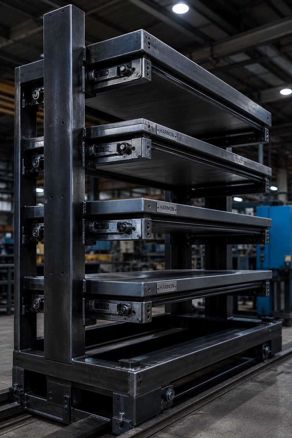
- Frame gauge and upright profile - The vertical columns supporting each shelf level must resist both the static dead load and the dynamic moment forces created when a loaded shelf extends outward. Heavier gauge steel (lower gauge numbers mean thicker material) with deeper upright profiles provides greater resistance to column buckling. A rack using 7-gauge (0.179-inch) steel in a 3x3 tubular profile handles dramatically different loads than one built from 11-gauge (0.120-inch) C-channel uprights.
- Rail type and construction - The guide rails carrying each sliding shelf must support the full vertical load while allowing horizontal travel. Light-capacity racks often use single-piece roll-formed rails, while heavy duty die rack capacity ratings above 5,000 lbs typically require machined or structural rail assemblies with hardened raceways. Rail deflection under load directly limits how much weight a shelf can carry without binding during extension.
- Bearing type and quantity - Roller bearings distribute shelf weight across the rail surface. Standard ball-bearing trucks work well up to moderate loads, but shelves rated above 8,000 lbs generally use precision roller bearings with higher dynamic load ratings. More bearing trucks per shelf distribute weight across more contact points, reducing point loading on any single rail section.
- Shelf width and depth - Wider and deeper shelves require stiffer construction to prevent sagging under load. A 48-inch-wide shelf carrying 4,000 lbs experiences less bending stress per linear inch than a 72-inch-wide shelf at the same load. Depth matters too: deeper shelves extend the moment arm when fully rolled out, increasing the tipping force that the frame must resist.
- Pneumatic cylinder count and bore - While cylinders primarily handle horizontal extension force rather than vertical load bearing, their capacity determines the maximum shelf load that can actually be moved. Undersized cylinders stall under heavy loads. The pneumatic rack frame gauge and rail type must be matched to cylinder output so the system can extend its rated capacity reliably.
These factors do not operate in isolation. A rack with excellent frame steel but undersized rails will fail at the rail. One with heavy rails but thin-gauge uprights will buckle at the column. Capacity ratings reflect the system's balanced engineering, not any single component's strength.
Matching Die Weight to Rack Configuration
Manufacturers build pneumatic roll out racks in distinct capacity tiers because the engineering steps between them are not linear. You cannot simply add thicker steel to a light-duty design and call it heavy-duty. Each tier represents a fundamentally different structural approach. The table below shows how typical specifications shift across common capacity ranges:
| Capacity Tier (Per Shelf) | Frame Gauge / Upright | Rail Type | Bearing Configuration | Cylinders Per Shelf | Typical Shelf Depth |
|---|---|---|---|---|---|
| 2,000 - 4,000 lbs | 10-gauge formed C-channel or 3x3 tube | Roll-formed single-piece rail | 4-6 ball-bearing trucks | 1 (2.5-3" bore) | 36" - 48" |
| 4,000 - 10,000 lbs | 7-gauge structural tube (3x3 or 4x4) | Dual-rail with hardened raceway | 6-8 roller-bearing trucks | 2 (3-4" bore) | 48" - 60" |
| 10,000 - 20,000 lbs | 1/4" plate or heavy structural (4x6+) | Machined structural rail assembly | 8-12 precision roller-bearing trucks | 2-4 (4-6" bore) | 48" - 72" |
Notice the jump between the mid-tier and the 20000 lb roll out rack specifications. At that level, you are no longer working with standard roll-formed components. The uprights shift to plate steel or heavy structural sections, rails become multi-piece machined assemblies, and the rack often requires four pneumatic cylinders per shelf to generate enough extending force. These racks are essentially custom-engineered structures, not catalog items with options checked off.
For buyers, the practical takeaway is straightforward: identify your heaviest die, add a 15-20% safety margin, and select the capacity tier that comfortably exceeds that number. A 6,500-pound die needs a rack rated for at least 7,500-8,000 lbs per shelf, placing it firmly in the mid-tier configuration. Trying to save money by squeezing that die onto a 4,000 lb-rated shelf risks premature rail wear, bearing failure, and cylinder stall, all of which cost far more to repair than the initial price difference between tiers.
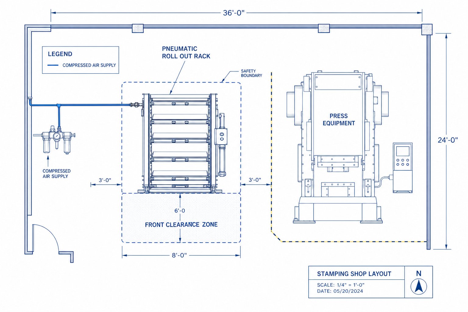
Floor space is the other half of this equation. A pneumatic roll out rack storing six dies vertically in a 6-foot by 5-foot footprint replaces what would otherwise require a row of floor-level static racks spanning 18 to 24 linear feet, plus a dedicated crane path above them. The trade-off is height versus floor area. Roll out racks consolidate dies into a compact vertical stack and only need clearance in front for the shelf to extend, typically the shelf depth plus 12 to 18 inches of safety margin. Compared to crane-accessed static storage where each die sits at floor level needing its own overhead lifting zone, the roll out approach can reclaim 40-60% of the floor space dedicated to die storage while eliminating the scheduling conflict of shared crane access.
Capacity ratings and footprint planning get you to the right rack on paper. But the rack still needs to connect to your facility's infrastructure, and that is where overlooked installation requirements quietly turn a good specification into a costly retrofit project.
Installation Requirements and Facility Preparation
A pneumatic stamping die roll out rack does not operate in isolation. It connects to your compressed air system, bears down on your concrete slab, and needs specific clearances to function safely. Skip any one of these preparation steps and you end up with a rack that stalls mid-extension, cracks your floor, or cannot be serviced without moving adjacent equipment. These are the pneumatic roll out rack installation requirements that manufacturers mention in passing but rarely explain in detail.
Compressed Air Supply and CFM Specifications
Your rack's pneumatic cylinders consume air every time a shelf extends or retracts. The question is whether your existing shop air system can handle that demand without starving other equipment.
A typical double-acting cylinder with a 4-inch bore and 48-inch stroke consumes approximately 1.5 to 2.5 CFM per full extension-retraction cycle at 100 PSI. That sounds modest until you consider a six-shelf rack where multiple shelves might cycle within the same time window. Peak demand matters more than average demand. If three shelves extend simultaneously during a die changeover rush, your compressed air CFM requirements for the die rack spike to 6-8 CFM instantaneously.
The real pitfall is not total compressor capacity but line sizing and pressure drop. As Unipipe Solutions explains, undersized pipes create friction-induced pressure loss that starves end-use equipment. A 1/2-inch supply line running 50 feet from a header to a rack may deliver adequate volume at low flow, but at peak demand, pressure drop can reduce your 100 PSI supply to 75 PSI at the rack. That 25% pressure loss translates directly into 25% less cylinder force, potentially causing shelves to stall under heavy loads.
Size the supply line based on peak simultaneous CFM demand, not average. For most pneumatic die rack installations, a 3/4-inch to 1-inch supply line with a dedicated drop from the main header prevents starvation issues. Include a moisture separator and filter regulator at the rack to protect cylinder seals from condensation and particulate contamination in the air supply.
Floor Load Capacity and Anchoring Requirements
A fully loaded six-shelf rack carrying 5,000 pounds per level concentrates 30,000 or more total pounds into a footprint of roughly 30 to 35 square feet, plus the rack's own dead weight. That creates point loads at each base plate that can exceed what a standard 4-inch warehouse slab was designed to handle.
Floor load capacity for heavy die storage rack installations depends on three factors that Cisco-Eagle identifies as critical for any heavy rack system: concrete slab thickness, yield strength in PSI, and subgrade condition beneath the slab. A 6-inch slab poured at 4,000 PSI over well-compacted subgrade handles most die rack installations. A 4-inch slab on clay subgrade may not, particularly if moisture-driven settling has already created micro-cracks around existing anchor points.
Anchoring is non-negotiable. Pneumatic roll out racks experience dynamic forces when loaded shelves extend outward. That extension shifts the center of gravity forward, creating a tipping moment that the anchors must resist. Typical roll out rack anchoring and clearance specs call for 3/4-inch wedge anchors or epoxy anchors at each base plate, embedded a minimum of 4 inches into sound concrete. Before drilling, confirm that no rebar, post-tension cables, or radiant heating lines exist in the planned anchor locations.
Never assume a given floor can handle a heavy rack system without confirmation. Only a qualified engineer or architect can safely evaluate slab capacity, subgrade condition, and anchor placement for loads exceeding 20,000 total pounds.
Pre-Installation Facility Checklist
Gathering this information before contacting installers prevents costly surprises on delivery day. As General Kinematics emphasizes, early planning addresses major issues like foundational damage or utility shortfalls that multiply in cost the later they are discovered. Use this checklist to assess your facility readiness:
- Compressed air supply - Confirm compressor CFM capacity at peak demand, measure available PSI at the planned rack location (not at the compressor), verify supply line diameter is 3/4-inch minimum for runs under 30 feet or 1-inch for longer runs, and confirm a dedicated drop point is available or can be added.
- Floor assessment - Obtain slab thickness and concrete PSI rating from facility drawings or core samples. Calculate total rack load including all dies at maximum capacity. Verify subgrade stability. Identify any existing cracks, joints, or embedded utilities in the installation footprint.
- Clearance requirements - Measure available space in front of the rack equal to the maximum shelf extension depth plus 18 inches of safety margin. Confirm overhead clearance for crane or hoist access to extended shelves. Verify aisle width accommodates die transport once removed from the shelf.
- Utility access - Locate the nearest air header drop and measure the run distance. Confirm electrical access if the rack uses solenoid-operated valves or control panels. Plan routing paths for air lines that avoid forklift traffic zones and overhead obstructions.
- Delivery and placement path - Verify that dock doors, aisles, and corridor widths can accommodate rack frame sections during delivery. Confirm rigging equipment availability for positioning the assembled rack if it cannot be built in place.
The common thread across these items is measurement over assumption. Shops that install pneumatic roll out racks without verifying air pressure at the point of use, slab ratings at the exact footprint, or clearance with shelves fully extended are the ones that spend thousands on post-installation corrections. A $200 slab core sample or a $50 pressure gauge test at the planned location prevents a $5,000 floor repair or a $3,000 air system retrofit after the rack is already bolted down.
Infrastructure readiness gets the rack installed. Keeping operators safe around shelves carrying multi-ton dies requires an equally deliberate approach to loading procedures and ergonomic protocols.
Safety Protocols for Loading and Accessing Stored Dies
A shelf rated for 10,000 pounds does not care whether the operator standing beside it followed the correct procedure. The physics of a multi-ton die sliding outward on rails are unforgiving. One missed step during loading or unloading, a shelf extended past its limit, a die placed off-center, or a pneumatic system re-pressurized while someone is working in the travel path, and the consequences range from crushed tooling to catastrophic injury. These systems handle extreme weights, so the safe loading procedure for a roll out die rack must be deliberate, sequential, and non-negotiable.
Safe Loading and Unloading Procedures for Heavy Dies
Every interaction with a loaded shelf follows the same core sequence. Skipping steps might save 30 seconds, but the risks at these weight levels make shortcuts indefensible. The pneumatic rack safety lockout procedure is especially critical because compressed air stores energy that can drive a shelf outward without warning if a valve is accidentally triggered.
- Verify the stamping die roll out shelf weight limits - Confirm the die weight against the shelf's rated capacity before any loading begins. Include the weight of any sub-plates, bolster adapters, or fixtures loaded alongside the die. Exceeding the rated capacity risks rail deformation, bearing failure, or cylinder stall during the next extension cycle.
- Lock out the pneumatic supply - Close the air supply valve serving the target shelf and bleed residual pressure from the cylinder lines. Apply a personal lockout device to the isolation valve. As the UCSC lock-out tag-out program emphasizes, pneumatic energy is one of the hazardous sources that must be isolated and rendered inoperative before servicing or loading work begins. Verify isolation by attempting to activate the shelf control. The shelf should not move.
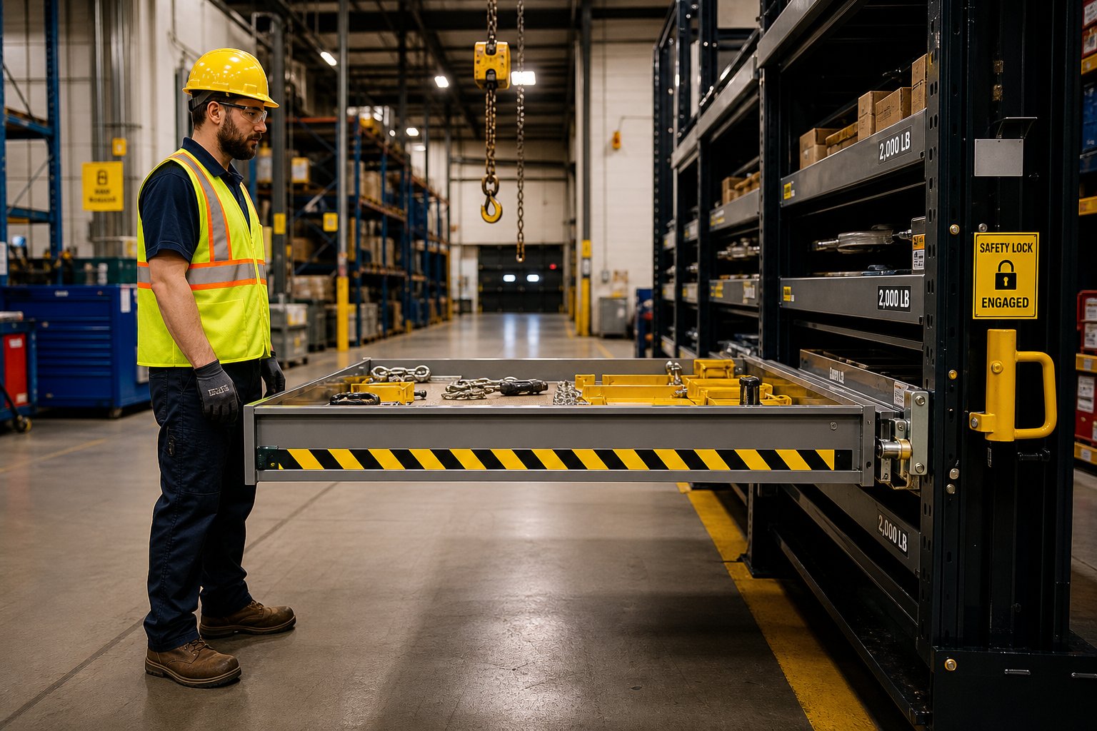
- Extend the shelf to the loading position - Release the lockout only after all personnel are clear of the travel path. Extend the shelf using normal controls, then re-engage the mechanical safety lock that holds the shelf in the fully extended position. Confirm the lock is seated before approaching.
- Center the die on the shelf - Position the die so its center of gravity aligns with the shelf's centerline, both side-to-side and front-to-back. Off-center placement creates uneven rail loading and increases the tipping moment during retraction. Use marked placement guides or stops if available.
- Lower the die gradually - Whether using an overhead hoist or forklift, lower the die onto the shelf surface slowly and evenly. Avoid dropping or releasing from height. Confirm the die is fully seated and stable before disconnecting rigging or withdrawing fork tines.
- Clear all personnel from the retraction path - Before retracting, verify that no tools, hands, or body parts are between the shelf edge and the rack frame. The closing force of a pneumatic cylinder retracting a loaded shelf can exceed 1,000 pounds.
- Retract and verify the lock - Retract the shelf using normal controls and confirm the retracted-position safety lock engages. Tug-test the shelf to verify it will not drift outward.
Unloading follows the same sequence in reverse, with the same lockout discipline before any hands enter the shelf zone. The principle is simple: never place any part of your body in a pinch point or travel path unless the energy source driving shelf movement is physically isolated.
Ergonomic Benefits and OSHA Considerations
Safety is not only about preventing acute crushing injuries. Repetitive access to heavy die storage creates cumulative musculoskeletal damage that develops invisibly over months and years. OSHA's ergonomics technical manual identifies repetitive exertion, heavy lifting, and sustained awkward postures as primary contributors to back disorders, which affect over 600,000 workers annually. Manual materials handling remains the principal source of compensable injuries in the American workforce.
Pneumatic assistance addresses the specific OSHA ergonomic guidelines for heavy die handling by eliminating the two most damaging repetitive actions: the high-force push needed to break a loaded shelf free from static friction, and the sustained pulling effort to retract it. Without pneumatic help, an operator extending a 5,000-pound shelf multiple times per shift accumulates the kind of repetitive upper-body and back loading that OSHA's prevention guidelines explicitly flag. Engineering controls like lift-assist devices and mechanized material handling are OSHA's preferred solution over relying on worker training or rotation alone.
The ergonomic payoff compounds with access frequency. A shop pulling dies 8 to 10 times per shift eliminates thousands of high-force exertions per year by using pneumatic actuation instead of manual cranking. That translates directly into fewer lost-workday injuries, lower workers' compensation costs, and operators who can sustain productive careers without chronic back or shoulder damage. The rack is not just a storage device. It is an engineering control that removes a recognized ergonomic hazard from the daily work pattern.
Protecting operators during each access event is half the equation. Protecting the rack system itself, so it continues operating safely year after year, requires a structured maintenance approach that most buyers never think about until something fails.
Maintenance Requirements and Total Cost of Ownership
A pneumatic stamping die roll out rack that runs flawlessly on day one will not stay that way without structured upkeep. Compressed air systems are generally reliable, but the seals, bearings, and lubrication points that keep multi-ton shelves gliding smoothly all have finite service lives. The problem is that no rack manufacturer publishes a detailed pneumatic roll out rack maintenance schedule. Buyers find out what is required after something slows down, leaks, or stops entirely. Here is the preventive approach that keeps repair costs from outpacing the rack's value.
Preventive Maintenance Schedule for Pneumatic Cylinders
Pneumatic cylinders are the hardest-working components in the system, cycling under heavy load every time a shelf extends or retracts. According to Tameson's cylinder maintenance guidelines, wear and tear is inevitable, but taking simple preventive measures consistently and correctly extends cylinder life significantly and saves both time and money.
The air cylinder seal replacement interval on a die rack depends on cycle frequency and air quality. In a typical stamping shop accessing dies 5 to 10 times per shift, cylinder seals last 3 to 5 years before degradation causes noticeable leakage. Shops with poor air filtration or high humidity may see seal life drop to 18-24 months. Contamination, insufficient lubrication, and side loading are among the most common causes of premature cylinder failure, and all three are preventable with routine attention.
The table below outlines core maintenance tasks, recommended intervals, and the time investment each requires:
| Maintenance Task | Frequency | Estimated Time | Consequence of Neglect |
|---|---|---|---|
| Inspect cylinder rod and seals for wear or leakage | Monthly | 15-20 min per rack | Internal leakage, force loss, slow extension |
| Check and replace inline air filters | Every 3 months | 10 min | Contamination damages seals and valve internals |
| Lubricate guide rails and bearing trucks | Every 3 months | 20-30 min per rack | Increased rolling friction, cylinder overload |
| Drain moisture separator and inspect regulator | Weekly | 5 min | Water corrodes cylinder bore, degrades seals |
| Test safety locks for full engagement | Monthly | 10 min per rack | Uncontrolled shelf drift under load |
| Replace cylinder seals (full rebuild) | Every 3-5 years | 2-4 hours per cylinder | Complete cylinder failure, shelf inoperable |
| Inspect and re-torque anchor bolts | Annually | 30 min | Frame shift under dynamic loading |
| Replace bearing trucks (if worn) | Every 7-10 years | 3-5 hours per shelf | Binding, uneven extension, rail damage |
Most of these tasks require basic tools and a maintenance technician familiar with pneumatic systems. The critical discipline is consistency. A missed quarterly lubrication cycle forces cylinders to work harder against increased friction, accelerating seal wear and compounding the problem across multiple components simultaneously.
Troubleshooting Common Pneumatic Rack Issues
When a shelf that used to extend smoothly starts hesitating or losing speed, the instinct is often to blame the cylinder. But troubleshooting a slow pneumatic roll out shelf requires looking at the entire air path before assuming the actuator has failed. As BL Pneumatic's troubleshooting guide explains, slow actuation or force loss frequently originates upstream of the cylinder itself, in restricted flow paths, pressure drops, or exhaust restrictions that only reveal themselves during motion under load.
Start with these common culprits, ordered from most to least frequent:
- Clogged exhaust silencers - Oil and particulate buildup restricts the outgoing air from the opposing cylinder chamber. The shelf fights trapped air pressure, slowing dramatically. Remove and clean or replace silencers quarterly.
- Pressure drop under demand - The gauge reads 100 PSI at rest, but during extension it falls to 70-80 PSI. Undersized supply lines, clogged filters, or compressor recovery lag cause this. Measure pressure while the shelf is actually moving, not at idle.
- Worn piston seals - Air bypasses internally around the piston, reducing effective force. Symptoms include hissing from exhaust ports during hold, slow extension under load, and inability to reach full rated speed. Visible corrosion or premature wear on the cylinder body often accompanies advanced seal degradation.
- Dry or contaminated guide rails - Rolling friction increases when rail lubrication breaks down or metal debris accumulates on bearing surfaces. The cylinder output has not changed, but the load it pushes has effectively gotten heavier.
- Flow control valve misadjustment - Speed-regulating valves can drift from vibration or get bumped during adjacent work. A needle valve closed an extra half-turn cuts shelf speed noticeably. Check and record valve positions during routine maintenance.
A useful diagnostic principle: if the shelf moves slowly in one direction but normally in the other, the problem is almost always in the flow path for that direction, either supply-side restriction or exhaust-side blockage. Slow movement in both directions points to a systemic issue like low supply pressure, worn seals, or mechanical binding in the rails.
Total Cost of Ownership Considerations
Upfront purchase price tells you what the rack costs today. Total cost of ownership for pneumatic die storage tells you what it costs over its working life, and that number includes energy consumption, maintenance labor, replacement parts, and downtime.
Compressed air is not free. Running shop air to pneumatic cylinders costs electricity at the compressor. Industry estimates place the cost of generating compressed air at roughly $0.25 to $0.35 per 1,000 cubic feet, depending on local electricity rates and compressor efficiency. A six-shelf rack cycled 10 times per shift consumes approximately 15-25 cubic feet of air daily, making direct energy costs minimal: a few dollars per month. The real energy cost is the infrastructure. If the rack pushes your compressor into running an additional duty cycle to maintain header pressure, that incremental load matters more than the rack's direct consumption.
Maintenance costs are moderate and predictable. Based on the schedule above, expect roughly 8-12 hours of maintenance labor per rack annually for routine inspections, lubrication, and filter changes. Seal rebuilds every 3-5 years add a one-time burst of $500-$1,500 per cylinder depending on bore size and accessibility. Comparing this against actuator TCO analysis data showing pneumatic systems averaging $100-$400 in annual maintenance costs per actuator aligns well with die rack cylinder service expenses.
How does this compare across system types over a 15-year horizon?
- Manual crank systems - Lowest maintenance cost (lubrication and bearing checks only), but zero pneumatic components means zero air-related expenses. Expected life: 20+ years. Total maintenance spend over 15 years: $2,000-$4,000 per rack.
- Pneumatic systems - Moderate maintenance with seal rebuilds as the primary recurring expense. Expected cylinder life before replacement: 8-12 years with proper air quality. Total maintenance spend over 15 years: $5,000-$10,000 per rack including one full cylinder rebuild cycle.
- Hydraulic systems - Highest maintenance burden due to fluid changes, hose inspections, pump servicing, and leak management. Expected life: 15-20 years. Total maintenance spend over 15 years: $10,000-$18,000 per rack.
- Electric systems - Low recurring maintenance but higher repair cost when motors or control boards fail. Expected life: 10-15 years for motors. Total maintenance spend over 15 years: $4,000-$8,000 per rack.
The pneumatic system sits in a middle position: more maintenance than manual or electric, significantly less than hydraulic. What justifies the maintenance investment is the operational return. Faster access, eliminated ergonomic injuries, and reduced dependency on overhead cranes all generate value that compounds daily. A rack that saves 5 minutes per die change across 8 changes per shift recovers 40 minutes of production time daily. Over 250 working days, that is 166 hours of reclaimed press time annually, a value that dwarfs the $500-$800 annual maintenance investment.
The real cost mistake is not maintenance itself. It is buying a rack without understanding these ongoing requirements and then deferring service until a cylinder stalls under a 6,000-pound load at the worst possible moment during a production run. Planned maintenance is a budget line item. Unplanned failure is an emergency with multiplied costs in downtime, expedited parts, and potential safety incidents.
How to Select the Right Pneumatic Roll Out Rack for Your Operation
Knowing how these systems work, what capacity tiers exist, and what maintenance looks like still leaves one question unanswered: how do you actually specify the right rack for your specific operation? The gap between understanding pneumatic roll out technology and placing a correct order is where thousands of dollars get wasted. Buyers either over-specify and pay for capacity they never use, or under-specify and discover the shortfall after installation when shelves stall, floors crack, or air systems cannot keep up.
A structured decision framework eliminates guesswork. Gather the right inputs, avoid the documented pitfalls, and you arrive at a specification that matches your operation rather than a generic catalog selection that sort of fits.
Key Specification Inputs for Rack Selection
Before contacting any manufacturer or distributor, assemble these data points. Walking into a conversation without them guarantees you will receive a generic quote rather than a solution matched to your actual conditions. Think of this as your pneumatic die rack specification checklist:
- Individual die weights - Weigh every die that will be stored in the rack, not just the heaviest one. Record the heaviest die, the average die weight, and the lightest die. The heaviest die determines minimum shelf capacity rating (add 15-20% safety margin). If your heaviest die weighs 7,200 lbs, you need shelves rated for at least 8,500 lbs.
- Die dimensions (L x W x H) - Measure each die's footprint and height including any protruding components, guide pins, or sub-plates. These dimensions determine minimum shelf width, depth, and the vertical spacing between shelf levels. A die that is 48 inches wide needs a shelf at least 54 inches wide to allow clearance for hoist rigging on both sides.
- Number of dies to store - Count the total dies that need dedicated storage positions. This determines how many shelf levels and potentially how many rack units you need. Factor in growth: if your die library is expanding, plan for 20-30% additional capacity beyond current count.
- Access frequency per shift - Track how many times each die position gets accessed during a typical production shift. High-frequency positions (8+ accesses per shift) should be placed at ergonomically optimal heights. This frequency also validates whether pneumatic assist is necessary or whether lower-frequency positions could use manual systems at lower cost.
- Available floor space and ceiling height - Measure the exact footprint available including the clearance zone in front of the rack where shelves extend. You need shelf depth plus 18 inches minimum in front, and adequate overhead clearance for crane or hoist access to the extended shelf surface.
- Existing compressed air supply - Record your compressor's rated CFM output, the PSI available at the planned rack location (measured under load, not at idle), the distance from the nearest air header drop, and the existing supply line diameter. This determines whether your current infrastructure supports the rack or requires upgrades.
- Floor slab specifications - Obtain concrete thickness, PSI rating, and subgrade condition from facility drawings or engineering assessments. This information tells you and the manufacturer whether the planned location can handle the concentrated load without reinforcement.
- Die handling equipment - Document what equipment you use to lift dies onto and off shelves: overhead bridge crane, jib crane, forklift with specialized attachment, or hoist on monorail. The handling method affects required clearances above the rack and shelf extension positioning.
- Environmental conditions - Note ambient temperature range, humidity levels, and any airborne contaminants (metal dust, coolant mist) present in the storage area. These factors affect seal life, corrosion potential, and lubrication requirements for the pneumatic system.
This stamping die rack sizing guide for buyers covers the inputs that separate a well-matched specification from a generic one. The more complete your data, the more accurately a manufacturer can recommend the correct capacity tier, frame configuration, and cylinder sizing for your application. Incomplete inputs force manufacturers to over-spec for safety, and you pay for that conservatism.
Common Mistakes When Specifying Pneumatic Roll Out Racks
Even experienced tooling managers make specification errors that only become apparent months after installation. These are not theoretical risks. They are the common mistakes buying roll out die storage that facilities encounter repeatedly, each one costing anywhere from a few thousand dollars in retrofits to tens of thousands in wasted capacity or premature failure.
Specifying by average die weight instead of maximum die weight. A shop with dies ranging from 1,800 to 6,400 lbs might calculate a 3,500 lb average and select a rack rated for 4,000 lbs per shelf. That heaviest die at 6,400 lbs now has nowhere to go, or worse, gets loaded onto an under-rated shelf anyway. Always size to the maximum, not the average.
Ignoring floor load requirements. As BHD Storage Solutions emphasizes, evaluating floor condition, levelness, and load-bearing capacity beforehand is crucial to prevent misalignment, instability, and potential collapse. A fully loaded pneumatic rack concentrates extreme point loads at its base plates. Facilities that skip slab assessment before ordering frequently discover their floor cannot handle the load after the rack is delivered and partially assembled, triggering expensive remediation work with the clock running on installation labor costs.
Underestimating air supply needs. Buyers confirm their compressor has enough total CFM but never measure delivered pressure at the planned rack location under load. A 50-foot run of undersized pipe can drop pressure 20-30 PSI, reducing cylinder force below what is needed to extend heavy shelves reliably. The fix after installation means running new air lines, often requiring shutdown time and pipe fitting labor that costs $2,000-$5,000.
Forgetting shelf extension clearance. The rack fits beautifully against the wall or between columns. Then a shelf extends 48 inches outward and collides with a support column, adjacent equipment, or an aisle that is now too narrow for forklift traffic. Industrial shelving specification guides consistently identify ignoring aisle space as one of the costliest layout errors, and it applies doubly to roll out systems where the dynamic footprint during operation exceeds the static footprint at rest.
Selecting capacity without considering access frequency. Roll out rack selection by die weight and frequency should be a combined decision. A rack with the right capacity but insufficient cycle durability for high-frequency access will wear out its cylinders and bearings far sooner than the manufacturer's general life expectancy suggests. If you access a shelf 12 times per shift instead of the assumed 3-4 times, component life drops proportionally, and you hit seal replacement intervals in 18 months instead of 4 years.
Overlooking die construction quality as a storage variable. This one surprises most buyers. Dies that are poorly constructed, with rough edges, inconsistent base dimensions, or protruding components that were not designed with storage and handling in mind, create loading complications on roll out shelves. Off-center weight distribution from sloppy die construction increases uneven rail loading. Burrs and sharp edges damage shelf surfaces. Dies built with maintainability and handling in mind, where base dimensions are consistent and center of gravity is predictable, store more safely and reduce wear on rack components over time. This is where die manufacturing quality and storage planning genuinely intersect. Teams evaluating new custom stamping die manufacturing alongside storage infrastructure should consider how engineering attention to durability and maintainability in die construction, like what YICHEN builds into their stamping die programs, directly affects long-term handling safety and rack component wear. A well-constructed die with consistent dimensions and predictable weight distribution is simply easier and safer to store repeatedly over its service life.
Buying based on price per shelf rather than total cost of ownership. The cheapest rack per shelf level often uses thinner gauge steel, smaller bore cylinders, and lower-quality bearings. It meets the capacity rating on paper but wears faster, requires earlier maintenance, and may not deliver reliable extension speed under full load as components age. The maintenance and total cost of ownership analysis from the previous section shows that initial savings of $3,000-$5,000 on a cheaper rack can easily be consumed by a single premature cylinder rebuild and the associated production downtime.
The thread connecting most of these mistakes is the same one that Lyon's shelving specification guide identifies across all industrial storage: underestimating future needs and confusing individual component ratings with system-level performance. A pneumatic roll out rack is not a single component. It is a system that interacts with your floor, your air supply, your dies, your operators, and your production schedule. Specify it as a system, not a catalog item, and you avoid the mistakes that cost thousands after the purchase order is signed.
Frequently Asked Questions About Pneumatic Stamping Die Roll Out Racks
1. How much weight can a pneumatic stamping die roll out rack hold per shelf?
Pneumatic roll out racks typically support between 2,000 and 20,000 pounds per shelf depending on configuration. Capacity is determined by frame steel gauge, rail type, bearing quantity, and cylinder bore size working together as a system. Light-duty racks use 10-gauge C-channel frames with single cylinders for loads up to 4,000 lbs, while heavy-duty units rated at 10,000 to 20,000 lbs use quarter-inch plate steel uprights, machined structural rail assemblies, and multiple 4 to 6-inch bore cylinders per shelf. Always select a capacity tier that exceeds your heaviest die by at least 15-20% safety margin.
2. What air pressure and CFM does a pneumatic roll out rack require?
Most pneumatic die roll out racks operate on standard shop air between 80 and 120 PSI. A typical double-acting cylinder with a 4-inch bore and 48-inch stroke consumes approximately 1.5 to 2.5 CFM per full extension-retraction cycle. Peak demand matters most: if three shelves on a six-shelf rack cycle simultaneously during a die changeover, instantaneous demand spikes to 6-8 CFM. The critical factor is delivered pressure at the rack under load, not compressor nameplate capacity. Undersized supply lines running 50 feet or more can drop pressure 20-30 PSI, causing shelf stall under heavy loads.
3. When should I choose pneumatic assist over a manual crank roll out rack?
Pneumatic assistance becomes strongly recommended when shelf loads exceed 3,000 pounds regardless of access frequency, or when dies weighing 2,000 to 3,000 pounds are accessed more than 5 times per shift. OSHA ergonomic guidelines limit repetitive push-pull force to under 50 pounds, and even geared manual cranks generate sustained upper-body loading at these weights that compounds into musculoskeletal injuries over months. Above 10,000 pounds per shelf, pneumatic or hydraulic actuation is physically required since manual operation becomes impossible.
4. How often do pneumatic roll out rack cylinders need maintenance?
Monthly visual inspections of cylinder rods and seals take 15-20 minutes per rack and catch early wear before performance degrades. Guide rails and bearings need lubrication every 3 months. Inline air filters require replacement quarterly. The major service interval is a full cylinder seal rebuild every 3 to 5 years in shops accessing dies 5-10 times per shift with proper air filtration. Poor air quality or high humidity can shorten seal life to 18-24 months. Annual maintenance labor runs approximately 8-12 hours per rack, with seal rebuilds adding $500-$1,500 per cylinder when due.
5. What floor requirements exist for installing a heavy die roll out rack?
A fully loaded six-shelf rack can concentrate 30,000 or more total pounds into a 30-35 square foot footprint, creating extreme point loads at each base plate. Most installations require a minimum 6-inch concrete slab poured at 4,000 PSI over well-compacted subgrade. Anchoring typically calls for 3/4-inch wedge or epoxy anchors embedded at least 4 inches into sound concrete at each base plate. Dynamic forces from shelf extension create tipping moments that anchors must resist. A qualified engineer should evaluate slab capacity before installation, and facilities should verify no rebar, post-tension cables, or utilities exist at planned anchor locations.


