


Understanding Stainless Steel Die Stamping for Flat Ribbon
You can get the grade right, the die design right, and even the press speed right, and still end up with scrap parts. Why? Because stainless steel die stamping flat ribbon isn't just one discipline. It sits at the intersection of material science, ribbon geometry, and process engineering. Treat any one of these in isolation and something downstream breaks.
This guide covers that intersection in full. Whether you're specifying material, designing tooling, or troubleshooting production issues, you'll find the connections between decisions here rather than scattered across separate references.
What Is Flat Ribbon Die Stamping
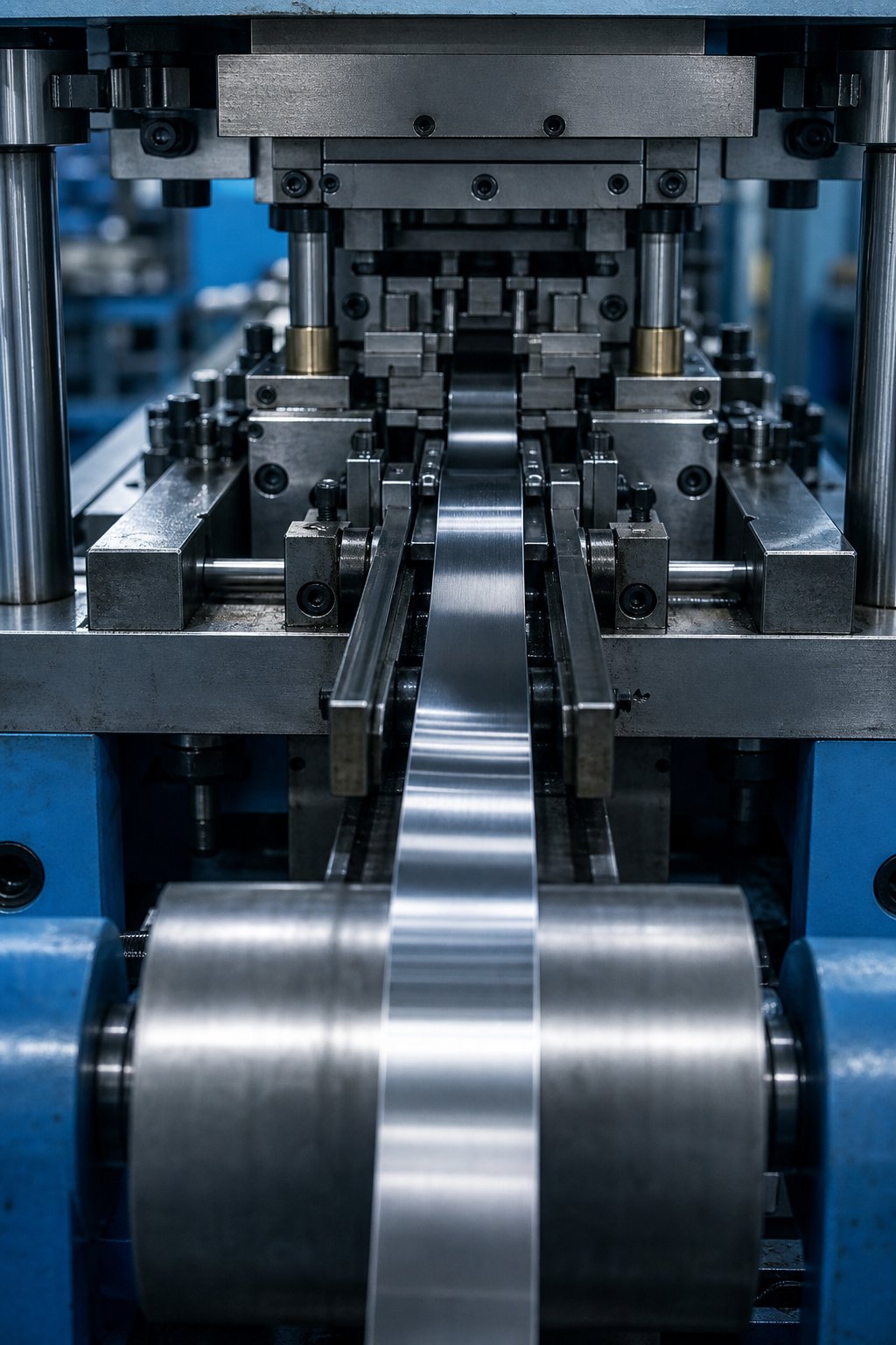
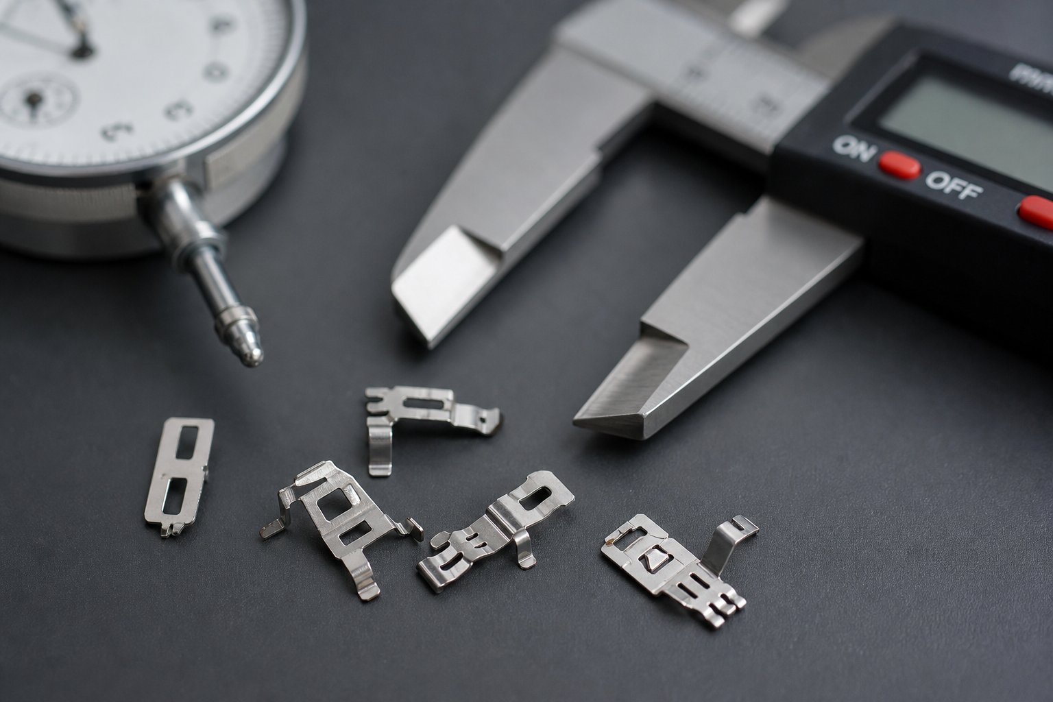
Flat ribbon die stamping is a cold-forming process where narrow coiled stainless steel ribbon feeds through progressive or single-station dies to produce precision parts. Each press stroke cuts, bends, or forms the ribbon into finished components. The ribbon stays attached to a carrier strip as it advances station by station, and the completed part separates at the final stage.
Stainless steel metal stamping in ribbon form follows the same fundamental mechanics as broader sheet stamping: a punch descends into a die block, shearing or deforming material under high pressure. The difference lies in scale, tolerances, and how the material behaves when it's narrow and thin.
Flat ribbon die stamping is the process of feeding narrow-width coiled stainless steel, typically under 50mm wide, through precision tooling to produce high-volume parts via sequential blanking, piercing, and forming operations.
Why Ribbon Stock Differs from Standard Sheet
Imagine running a 12mm-wide strip of half-hard 301 stainless through a 20-station progressive die at 300 strokes per minute. The challenges you'll face look nothing like stamping a 600mm-wide sheet blank.
Ribbon stock introduces unique variables. Width tolerances matter more because even slight variation affects how the strip tracks through guide rails and pilot pins. Edge condition, whether slit, sheared, or deburred, directly influences burr formation and die wear. And coil-set, the curvature retained from being wound on a spool, can cause misfeeds if flatness isn't controlled before the material enters the die.
In stainless stamping specifically, work hardening compounds these issues. A ribbon that feeds cleanly at station one may behave very differently by station fifteen as cumulative strain changes its mechanical properties. This is why material behavior, ribbon geometry, and die engineering must be considered as a single system rather than three separate line items on a spec sheet.
The grade you select, the temper you specify, and the tolerances you put on your purchase order all ripple forward into tooling life, part quality, and production speed.
Stainless Steel Grade Selection for Ribbon Stamping
Grade selection shapes everything that follows in your stamping process. Pick the wrong alloy for your ribbon application and you'll fight springback, premature die wear, or cracking at every station. The challenge is that grades behave differently in thin ribbon form than they do in heavier sheet, so experience with one doesn't always translate to the other.
Austenitic Grades for Ribbon Stamping
Nearly three-quarters of all stainless applications use austenitic 300-series grades, and ribbon stamping is no exception. The key players here are 301, 304, and 316, each with distinct behavior under the punch.
301 stainless steel stamping favors applications that need high strength after forming. With lower nickel content (6-8%), 301 work hardens rapidly, meaning it gains strength quickly during deformation. This makes it ideal for ribbon parts requiring spring properties, like contact fingers and clip fasteners. The tradeoff is that progressive dies must account for increasing hardness at each station.
304 stainless steel stamping suits deeper draws and more complex forming. Its higher nickel content (8-10%) slows the work-hardening rate, allowing material to flow without tearing as readily. When your ribbon part involves significant stretching or multi-stage draws, 304 gives you more forming headroom before the material stiffens to failure.
316 stainless steel stamping comes into play when corrosion resistance drives the specification, particularly in marine, chemical, or medical environments. The added molybdenum (approximately 2%) improves pitting resistance but doesn't dramatically change formability compared to 304. Engineers specifying 316 ss stamping for ribbon parts should expect similar elongation behavior to 304, with slightly higher force requirements due to solution strengthening from the molybdenum addition.
Martensitic and Specialty Grades
Not every ribbon part needs the ductility of austenitic steel. When the application demands high hardness, wear resistance, or elevated-temperature stability, martensitic and specialty grades enter the conversation.
410 ss stamping works well for ribbon components like valve seats, spring washers, and wear strips where hardness after heat treatment is the primary requirement. As a martensitic grade with 11.5-13.5% chromium, 410 offers moderate corrosion resistance but can achieve significantly higher hardness than any austenitic grade. The limitation is formability. Complex bends or deep draws in thin 410 ribbon risk cracking, so part geometry must stay relatively simple.
321 stainless steel stampings address a different need entirely. Stabilized with titanium to prevent chromium-carbide precipitation, 321 serves elevated-temperature applications where sensitization would degrade a standard 304 or 316 in service. Think exhaust components, sensor housings, or aerospace brackets exposed to sustained heat cycling.
Temper Selection and Its Impact on Die Performance
Choosing a grade is only half the equation. The temper condition you specify on your ribbon purchase order changes how that grade behaves under the die.
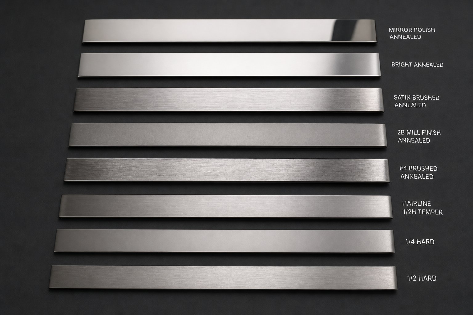
Annealed ribbon offers maximum ductility and the lowest forming forces, making it suitable for parts with tight bend radii or deep draws. Quarter-hard and half-hard conditions trade some formability for increased strength in the finished part, reducing or eliminating the need for post-stamping heat treatment. Full-hard ribbon, available primarily in 301 and 302, delivers spring-like properties but limits forming to gentle bends and simple blanking.
Here's the practical impact: as temper increases, springback grows because a larger portion of the stress-strain curve remains elastic. Your die designer must compensate with tighter over-bend angles or in-die coining. Meanwhile, harder tempers increase the shear force required at blanking stations, accelerating punch and die wear.
| Grade | Formability Rating | Typical Hardness Range | Common Ribbon Applications |
|---|---|---|---|
| 301 | Good (high work-hardening rate) | Refer to supplier datasheet for HRB/HRC by temper | Springs, clips, contact fingers, fastener components |
| 304 | Excellent (moderate work-hardening rate) | Refer to supplier datasheet for HRB/HRC by temper | Drawn parts, brackets, shielding, medical components |
| 316 | Excellent (similar to 304) | Refer to supplier datasheet for HRB/HRC by temper | Marine hardware, chemical processing, surgical instruments |
| 410 | Limited (low elongation) | Refer to supplier datasheet for HRC by heat-treat condition | Valve components, wear strips, blades, spring washers |
| 321 | Good (similar to 304) | Refer to supplier datasheet for HRB/HRC by temper | Exhaust parts, sensor housings, high-temperature brackets |
A practical rule: always request mechanical property certification with your ribbon coils. Variation within a temper range is normal, and knowing where your specific lot falls lets you anticipate whether forming behavior will trend toward the tight or forgiving end of your process window.
Grade and temper lock in the material's personality. But the ribbon itself, its edge condition, flatness, and dimensional tolerance, determines whether that personality translates into good parts or frustrating scrap rates.
Ribbon Stock Specifications That Drive Stamping Quality
Your material supplier ships coil that meets the grade and temper you ordered. It passes incoming inspection. And yet, parts start failing at station eight. Burrs appear where they shouldn't. Feed jams halt production every few hundred strokes. What went wrong?
More often than not, the answer lives in the ribbon stock specifications you didn't call out on your purchase order. Edge condition, flatness, camber, width tolerance, thickness tolerance, and surface finish are the variables that separate ribbon steel that runs beautifully from material that fights your tooling at every stroke. These aren't secondary details. They're the direct link between procurement decisions and manufacturing outcomes.
Edge Conditions and Their Stamping Implications
When a master coil gets slit into narrow ribbon, the cutting process leaves behind an edge profile that carries real consequences for your die. Three common edge types show up in stamped sheet metal production, and each behaves differently under the punch.
Slit edges are the default. The slitting knives shear through the parent coil and produce a square-ish edge with a characteristic burr on one side. That burr orientation matters. If it faces the die rather than the punch during stamping, you'll get inconsistent shear quality at blanking stations and accelerated wear on your die block entry radii. Slit edges work for many applications, but they demand that your die designer knows which side the burr sits on and accounts for it in clearance setup.
Sheared edges result from a different cutting mechanism that produces a cleaner face but can introduce micro-cracking along the edge in harder tempers. For steel for stamping applications involving subsequent edge forming or flanging, those micro-cracks become crack initiation points under stress.
Deburred or conditioned edges go through a secondary process that removes the slitting burr entirely and can round or square the edge profile to a controlled geometry. This edge type extends die life because it eliminates the abrasive burr that scores guide rails and feed mechanisms. As precision re-roll specialists note, conditioned edges also improve formability by preventing edge cracking during bending operations, a meaningful benefit when your ribbon part includes tight-radius flanges.
The cost difference between slit and conditioned edges is real, but so is the cost of replacing worn tooling or scrapping parts with edge-initiated cracks. Your application drives the right choice.
Flatness and Camber Specifications
Picture a ribbon coil unwinding into your feeder. If that material carries residual curvature from coiling (coil-set) or bows laterally across its width (crossbow), it won't track straight through guide rails and pilot pins. The result is misfeeds, mis-hits, and progressive damage to your tooling registration.
Flatness in ribbon foil and strip refers to how planar the material lies when uncoiled and placed on a flat surface. Waviness across the width or lengthwise undulations cause the ribbon to lift off the die face between stations, throwing off form depth and blanking alignment. For progressive dies running at speed, even minor waviness compounds across twenty stations into parts that drift out of tolerance.
Camber is the lateral curvature along the ribbon's length. Imagine the strip curving gently to one side like a shallow arc. In narrow stock, even a small camber value means the carrier strip walks sideways through the die, pulling pilot pins off-center and generating asymmetric burrs. The narrower your ribbon, the more sensitive your process becomes to camber because there's less material width to absorb lateral drift before pilots lose engagement.
Specifying flatness and camber on your purchase order isn't optional for precision stamping. It's the difference between a die that runs hands-off for an entire coil and one that needs operator intervention every few minutes.
Width and Thickness Tolerances for Precision Parts
Tighter incoming material tolerances give your die designer more room to work with. Here's why: die clearance, the gap between punch and die block, is set as a percentage of material thickness. If your ribbon arrives with thickness variation across the coil, that carefully calculated clearance becomes too tight in some areas and too loose in others. Too tight causes excessive punch wear and galling. Too loose produces rolled-over edges and heavy burrs.
Width variation creates a parallel problem. Your die's guide rails and stock lifters are machined to a fixed dimension. Ribbon that runs wider than nominal binds in the guides. Ribbon that runs narrower wanders laterally, degrading registration accuracy.
Industry-standard tolerances for precision ribbon range from +/-0.0001" for very thin gauges (0.002"-0.003") up to +/-0.001" for thicker material above 0.031". Width tolerances follow a similar pattern, tightening as the ribbon narrows. For widths under 0.250" (the range typically classified as ribbon rather than strip), tolerances of +/-0.001" to +/-0.005" are common depending on the width range.
When your stamped metal sheet or ribbon application demands tight part tolerances, you can't achieve them without equally tight incoming material control. The die can only hold dimensions that the raw material allows.
Here's what belongs on your purchase order when sourcing ribbon for precision die stamping:
- Edge condition type (slit, deburred, rounded, or custom) with burr-side orientation specified
- Maximum burr height if slit edges are acceptable
- Flatness tolerance (maximum deviation per unit length)
- Camber tolerance (maximum lateral bow per unit length)
- Width tolerance with measurement method specified
- Thickness tolerance with measurement location (center, edges, or both)
- Surface finish requirement (roughness value or visual standard)
- Coil inner diameter and maximum outer diameter for feeder compatibility
- Coil-set direction preference (burr-in or burr-out winding)
- Mechanical property certification per coil or per heat
Missing any of these on your sourcing documents means your supplier makes the decision for you, and their default may not match what your tooling expects. Every unspecified parameter is a variable that can shift between coil lots, quietly pushing your process toward its failure boundary.
Locking down material specs puts a ceiling on incoming variation. The next challenge is designing die clearances and tooling that work within that controlled envelope, especially when thin ribbon demands a fundamentally different approach to clearance calculation than heavier gauge work.
Die Design Considerations for Thin Ribbon Stock
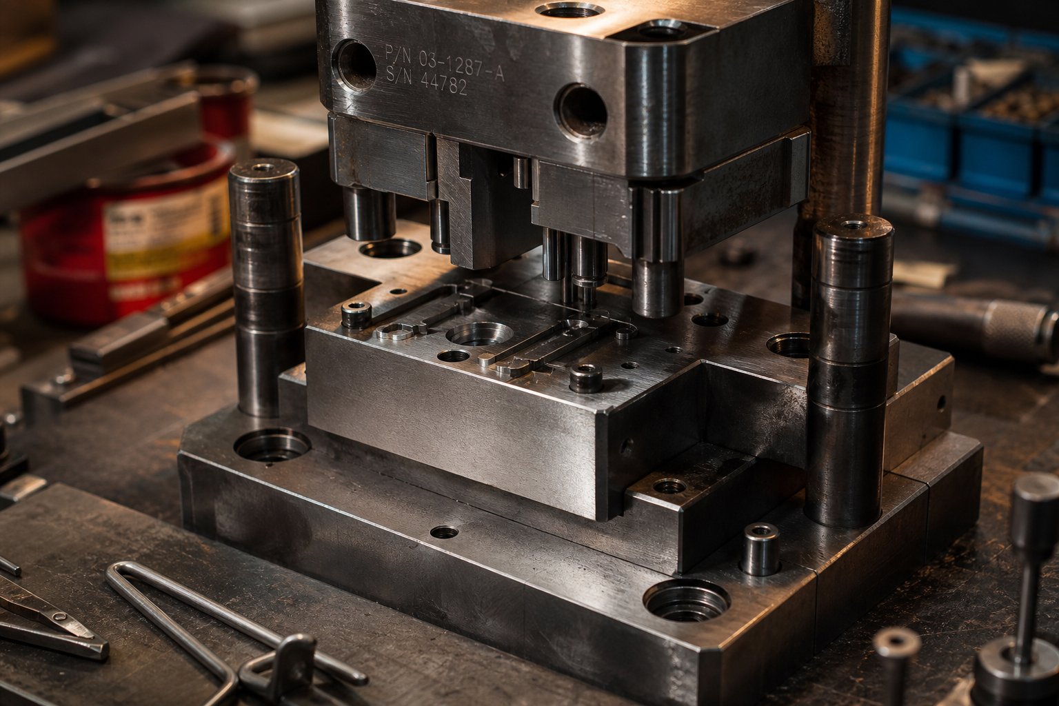
Thicker material forgives sloppy clearances. Thin ribbon does not. When you're stamping stainless steel ribbon at thicknesses below 0.5mm, the margin between a clean shear and a ragged edge shrinks dramatically, and every tooling decision carries amplified consequences for part quality and die life.
The principles of stainless steel precision stamping don't change at thinner gauges, but their application does. Clearances that produce perfect parts in 1.0mm sheet can generate excessive burrs or punch fracture in 0.1mm ribbon. Understanding why requires a closer look at how shear mechanics scale with thickness.
Die Clearance Calculations for Thin Ribbon
Die clearance is the gap between the punch cutting edge and the die button cutting edge, expressed as a percentage of material thickness per side. A 10% clearance on 1.0mm stock means 0.1mm of space on each side of the punch. Simple enough. But when you apply that same 10% to 0.05mm ribbon, you get 0.005mm per side, a dimension that challenges even precision-ground tooling to maintain consistently.
Here's what makes thin ribbon counterintuitive: the percentage itself often needs to increase slightly compared to standard sheet work. Why? Because the fracture planes at the top and bottom of the workpiece must align to produce a clean shear break. In very thin material, the shear zone becomes proportionally larger relative to total thickness, meaning the crack propagation path has less depth to work with. A clearance that's too tight at these gauges doesn't produce cleaner cuts. Instead, it generates excessive cutting force, accelerates punch wear, and can cause the punch to snap during penetration.
In thin ribbon stamping, tighter absolute clearances do not automatically mean cleaner cuts. The percentage-of-thickness clearance often must be carefully tuned upward to allow proper fracture alignment, because the shear-to-fracture ratio behaves differently as material thickness decreases.
For stamping stainless steel specifically, industry guidance suggests clearances of 12% to 15% per side for soft austenitic grades, scaling up to 20% for full-hard conditions. These values represent general starting points for standard sheet gauges. When working with ribbon under 0.25mm, you'll need to consult tooling engineering handbooks for grade-specific and thickness-specific clearance recommendations, then validate through trial runs because real-world behavior at these dimensions is highly sensitive to tooling condition and press alignment.
Precision matters here in a way it simply doesn't at heavier gauges. A press with 0.02mm of ram deflection is irrelevant when cutting 2.0mm stock, but that same deflection represents a 40% clearance shift on 0.05mm ribbon. This is why metal stamping for stainless steel ribbon often demands straight-side presses with minimal deflection rather than gap-frame machines, regardless of the tonnage requirement.
Tooling Material and Coating Selection
Stainless steel is abrasive by nature. Its chromium content, the same element that provides corrosion resistance, accelerates die wear through both abrasive and adhesive mechanisms. In ribbon stamping, this problem intensifies because you're running higher stroke counts per unit of material weight, meaning punches and die blocks accumulate wear faster than in heavier-gauge operations.
Conventional D-2 tool steel, while popular for general stamping, presents a specific problem with stainless ribbon. The high chromium content in D-2 can interface with the chromium in stainless steel, causing cold welding or surface-to-surface migration. This "pickup" deposits stainless material onto the punch face, degrading cut quality and eventually causing galling that damages both tool and workpiece.
Better choices for stamping dies manufacturing include:
- Powdered metal (PM) tool steels such as CPM grades or vanadium-carbide steels, which offer superior toughness and wear resistance compared to conventional wrought tool steels
- Aluminum bronze for forming stations, since it's completely dissimilar to stainless and resists adhesive pickup
- Solid carbide for blanking punches in long-run applications, providing exceptional wear life but requiring careful press setup due to its brittleness under shock loading
Coatings extend the equation further. Physical vapor deposition (PVD) coatings like titanium nitride (TiN) or aluminum titanium nitride (AlTiN) add a thin layer of high-hardness material that reduces friction and prevents the chrome-to-chrome interaction that causes galling. Chemical vapor deposition (CVD) coatings offer similar benefits with better adhesion on complex geometries. For ribbon stamping where punch cross-sections are small and fragile, PVD is generally preferred because it deposits at lower temperatures and doesn't risk distorting fine tooling features.
The investment in premium tool steels and coatings pays back in run length between sharpenings. When your progressive die has 15 to 25 blanking and piercing stations, multiplied by millions of strokes per production run, even a 30% improvement in sharpening interval translates to significant uptime gains.
Stripping and Part Ejection Challenges
You've cut the part cleanly. It looks perfect. But it won't leave the punch. This scenario is common in thin ribbon stamping, and it stems from physics that become dominant at small scales.
Thin ribbon parts cling to punches for two reasons. First, the surface area-to-mass ratio is very high. A tiny blanked disc weighing fractions of a gram has relatively large flat surfaces creating vacuum and surface-tension effects against the punch face. Second, springback in the pierced hole causes the slug or part to grip the punch sideways, particularly in harder temper conditions where elastic recovery is substantial.
Bridge strippers, the simplest and cheapest option, often fail at this job with ribbon stock. As tooling engineers have documented, bridge strippers don't hold material down during the cutting process, allowing sideways movement that stresses punches. During withdrawal, the strip slams against the stripper plate, sending shock into thin punches that may fracture under repeated impact.
Pressure-loaded (spring) strippers solve both problems. They clamp the ribbon flat against the die surface before and during punch penetration, preventing lateral movement. On the return stroke, they peel the strip off the punch gradually rather than through sudden impact. The higher initial cost is easily justified by reduced punch breakage and fewer production stoppages from stuck parts.
Additional techniques for reliable ejection in ribbon work include:
- Positive air blast through the punch face to break vacuum on slug retention
- Spring-loaded ejector pins within the punch body for blanked parts
- Polished punch faces (surface roughness below Ra 0.2 micrometers) to minimize adhesion
- Applying the same PVD coatings used for wear resistance, which also reduce the coefficient of friction during stripping
Every stuck part is a potential die crash. In progressive tooling running at high speed, a single retained slug can cascade into bent pilots, broken punches, and damaged die sections within a few strokes. Investing in reliable stripping isn't about convenience. It's about protecting the entire die.
Die clearance and tooling handle the individual cut. Stripping handles the aftermath. But the broader question of how to sequence multiple operations across a continuously fed ribbon, and whether progressive tooling is even the right choice for your volume, requires a different kind of engineering decision.
Progressive Die Stamping vs Short-Run Tooling for Ribbon Parts
Volume changes everything. A ribbon part destined for ten million units per year demands a fundamentally different tooling strategy than the same geometry at five hundred pieces. The tooling cost, lead time, and process control infrastructure scale accordingly, and choosing wrong in either direction burns money: over-investing in progressive tooling for a short run, or limping through high volume with single-station methods that can't keep pace.
For stainless steel ribbon specifically, this decision carries extra weight. The material's work-hardening behavior and abrasive nature mean that tooling choices have outsized consequences for die life and per-part cost at scale.
Progressive Die Stamping for High-Volume Ribbon Production
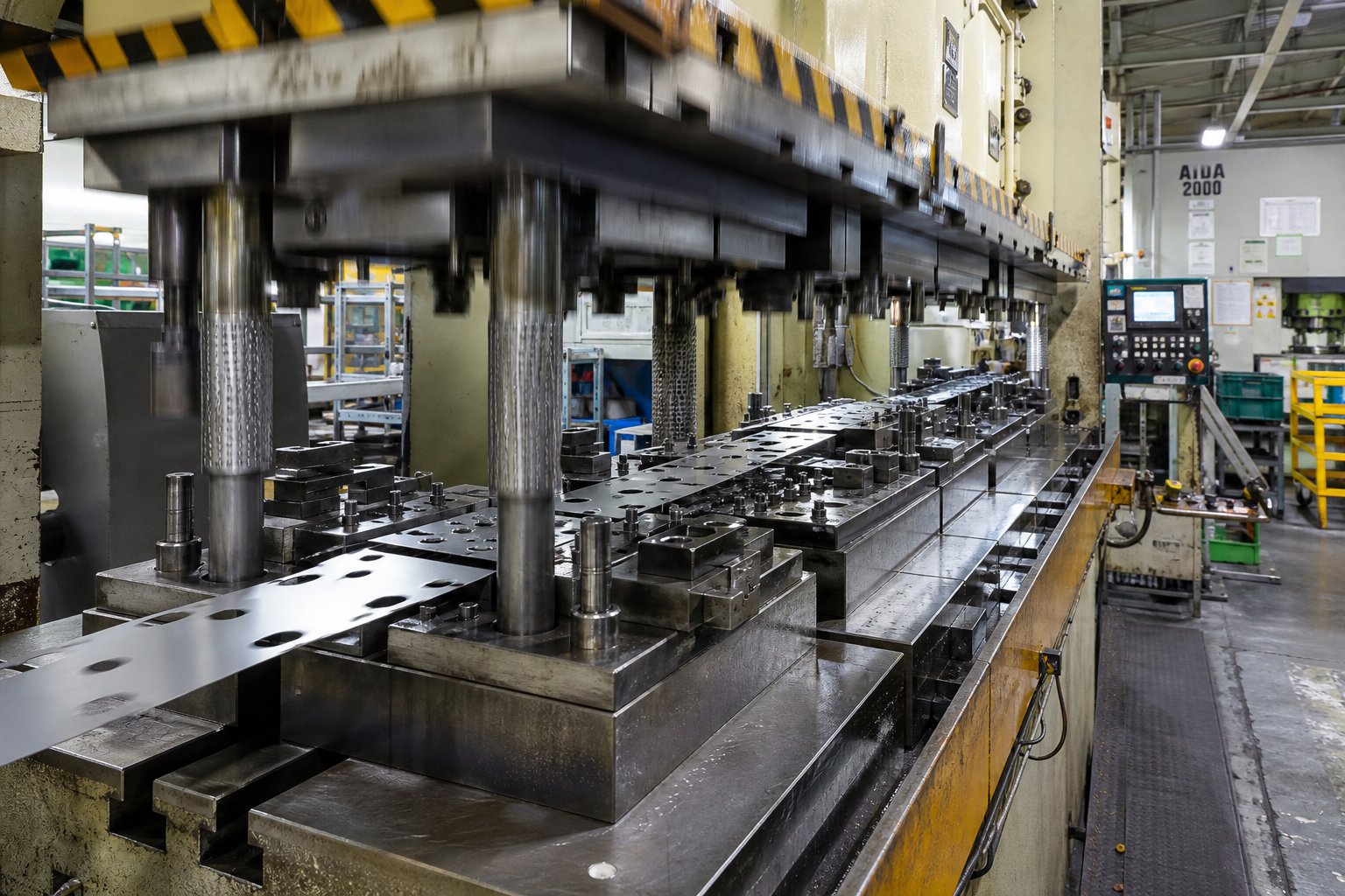
Progressive die stamping is the workhorse of long-run progressive stamping in ribbon form. A single die set contains multiple stations arranged in sequence, each performing one operation: blanking a pilot hole, piercing features, forming bends, coining critical dimensions, and finally separating the finished part from the carrier strip. The ribbon advances one pitch length per press stroke, so every cycle produces a completed part.
What makes this method dominant for high-volume ribbon work? Speed and consistency. A well-designed progressive die running stainless ribbon can sustain 200 to 600 or more strokes per minute, depending on part complexity and material thickness. At those rates, a single press shift can produce tens of thousands of identical parts with dimensional repeatability that individual station-to-station handling simply cannot match.
The economics reinforce the speed advantage. Progressive die tooling typically ranges from $30,000 to over $250,000, but that cost amortizes across the full production volume. At 500,000 parts, even a $100,000 die adds only $0.20 per piece in tooling cost. Below approximately 50,000 annual units, though, that amortization math starts working against you. This threshold is why progressive die stamping services generally target programs with sustained high demand rather than one-time orders.
For stainless ribbon, progressive dies also offer a process advantage beyond speed. Because the strip never leaves the die between operations, part registration stays locked to pilot-pin accuracy throughout the forming sequence. That matters when cumulative work hardening shifts the material's behavior across stations. You can predict and compensate for those shifts during die design rather than fighting random variation introduced by part handling between separate operations.
Coil Handling and Feeding for Narrow Stock
Running ribbon under 50mm wide at high speed introduces feeding challenges that broader coil stock doesn't face. The strip has less stiffness across its width, making it prone to buckling, twisting, and lateral drift in the feed path. Solve these problems and you get uninterrupted production. Ignore them and you get misfeeds, die crashes, and scrap.
Servo feeders are the standard indexing solution for precision ribbon stamping. A servo motor drives feed rollers that grip the strip and advance it by a programmable pitch length, synchronized to the press cycle. The programmability matters because stainless ribbon, particularly in harder tempers, can exhibit feed-length variation under grip pressure. Servo control allows real-time compensation that mechanical or pneumatic feeders cannot provide.
Pilot pins remain the final registration authority inside the die. Even with a perfectly tuned servo feeder, the pins correct any residual positional error by pulling the strip into exact alignment before each station engages. For narrow ribbon, pilot hole diameter and pin-to-hole clearance must be tight enough to control lateral position without binding, typically 0.01mm to 0.02mm total clearance for precision work.
Guide systems between the feeder and die entry also require attention. Wide stock naturally tracks straight because its moment of inertia resists lateral movement. Narrow ribbon doesn't have that luxury. Roller-style edge guides or channel-type stock guides keep the strip centered through the feed path. Spring-loaded designs accommodate the minor width variation inherent in slit ribbon without clamping so tightly that they buckle the strip or add drag that affects feed accuracy.
One often-overlooked detail: coil payoff tension. Ribbon coils have small inner diameters relative to their width, which means the material unwinds with more coil-set curvature than broader stock wound on larger mandrels. A straightener or flattener between the decoiler and feeder is essential. Without it, residual curvature lifts the ribbon off the die face between stations, causing inconsistent form depths and blanking misalignment.
Prototype and Short-Run Approaches
Progressive tooling makes sense when volume justifies the investment and the design is frozen. When neither condition is met, you need alternative methods that still produce acceptable stainless ribbon parts without the capital commitment.
Compound dies perform multiple operations in a single press stroke at one station. They're less expensive than progressive tooling because they require fewer stations and no strip carrier design. The tradeoff is throughput: parts must be individually handled between operations if multiple compound dies are needed, and stroke rates stay lower because each hit does more work simultaneously.
Transfer tooling separates the part from the strip early and moves it mechanically between stations. This approach suits parts whose geometry would tear a carrier strip, such as deep-drawn ribbon cups. However, the mechanical transfer mechanism limits speed compared to the continuous-flow logic of progressive dies, and the additional handling risk grows with thinner, more fragile ribbon parts.
Wire EDM and laser cutting bypass stamping entirely for prototype quantities. These methods cut parts directly from ribbon stock without hard tooling, producing accurate profiles in hours rather than weeks. The per-part cost is orders of magnitude higher than stamping, but when you need fifty parts for functional testing before committing to a $150,000 progressive die, that cost is trivial compared to the risk of tooling a flawed design.
It's worth noting that the decision framework differs slightly when comparing carbon steel progressive stamping economics to stainless. Stainless ribbon's higher material cost and greater die wear rate push the volume threshold for progressive tooling investment somewhat higher than equivalent carbon steel programs. The incremental tooling maintenance cost per stroke is simply larger with stainless, meaning you need more parts across which to spread it.
Here's a structured decision workflow for choosing your tooling strategy:
- Define annual volume and total lifetime quantity. If annual volume exceeds 50,000 units with multi-year demand, progressive tooling is likely justified.
- Assess part complexity. Count the number of distinct operations (piercing, forming, trimming). Parts requiring five or more sequential operations strongly favor progressive dies.
- Evaluate tolerance requirements. If critical dimensions demand +/-0.05mm or tighter across multiple features, progressive dies with pilot-pin registration outperform alternatives.
- Confirm design maturity. Progressive die investment requires a frozen design. If the part is still iterating, use wire EDM or compound dies for validation runs first.
- Calculate total cost of ownership. Compare progressive die cost amortized over lifetime volume against per-part cost of short-run methods multiplied by the same volume. Include die maintenance, sharpening intervals, and estimated scrap rate for each approach.
- Factor lead time. Progressive dies require 12 to 20 weeks to build. If production must start in four weeks, short-run methods bridge the gap while long-run progressive stamping tooling is fabricated.
The right answer often isn't purely one method or the other. Many successful programs begin with compound dies or wire-cut prototypes for design validation, then transition to progressive tooling once volume ramps and geometry locks. This staged approach protects capital while still delivering production-capable parts at each phase.
Tooling strategy determines how parts get made. But understanding where those parts end up, and how application requirements feed back into material and process decisions, completes the engineering picture.
Key Applications for Die-Stamped Stainless Steel Ribbon
Every material decision and tooling choice discussed so far ultimately serves one thing: the finished part's job in the real world. Application requirements don't just influence grade and temper selection. They dictate it. A contact spring that must survive a million flex cycles demands different ribbon properties than a surgical blade that contacts human tissue, even though both start as narrow stainless coil fed through a progressive die.
Understanding where stamped stainless steel parts end up helps engineers work backward from performance requirements to the correct material, temper, and process combination.
Electrical Contacts and Connector Springs
When you need a tiny component that flexes repeatedly without taking a permanent set, resists corrosion in humid environments, and maintains dimensional stability over years of service, you're describing a contact spring. This is where 301 stainless ribbon dominates.
Why 301 specifically? Its lower nickel content (6-8%) causes it to work harden more rapidly than other austenitic grades, meaning a half-hard or three-quarter-hard temper delivers spring properties that rival dedicated spring steels while adding inherent corrosion resistance. Electrical conductivity is secondary in these applications because the contact force and surface interface handle the electrical connection. What matters is fatigue life: the ability to flex millions of times without cracking.
Connector springs, battery contacts, RF shielding clips, and SIM card ejector mechanisms all rely on this combination of properties. The ribbon form factor suits these parts perfectly because finished components are typically narrow, thin, and produced in enormous quantities, exactly the profile where progressive die stamping excels.
Medical Device and Aerospace Components
Medical and aerospace applications share a common thread: failure isn't an option, and material traceability is mandatory. Beyond that, their requirements diverge sharply.
Medical ribbon parts, think surgical staples, retractor springs, implant anchors, and diagnostic sensor housings, require biocompatibility above all. Grade 316L (low carbon) is the standard because its molybdenum content resists pitting from body fluids while the low carbon prevents sensitization during welding or sterilization cycles. Surface finish matters intensely here. Stamped ribbon parts destined for patient contact must meet stringent surface roughness specifications to prevent bacterial adhesion and tissue irritation.
Aerospace drives different priorities. Stamping stainless steel aeronautical parts means working with grades that maintain mechanical properties at elevated temperatures and across extreme thermal cycling. Grade 321, stabilized with titanium against chromium-carbide precipitation, serves exhaust system components and engine bay brackets. For structural clips and fastener elements, 304 stainless steel stamped parts in annealed or quarter-hard temper provide the formability needed for complex geometries while delivering adequate strength-to-weight ratios at moderate service temperatures.
Both industries demand full material certification, lot traceability, and process validation, requirements that progressive die stamping supports well through its inherent repeatability and statistical process control capability.
HVAC and Industrial Sensor Components
Not every stamped ribbon part lives in a high-profile application. HVAC systems and industrial sensors consume millions of stamped stainless ribbon components annually, from bimetal actuator elements and thermostat springs to shielding clips, mounting brackets, and precision sensor housings.
HVAC progressive stamping produces components like damper linkage clips, flame sensor brackets, and duct-connection spring clips at volumes that justify dedicated progressive tooling. These parts typically use 304 in annealed or quarter-hard condition, balancing adequate corrosion resistance for humid environments against the formability needed for complex bracket geometries. HVAC progressive metal stamping operations often run continuously across multiple shifts, making die life and material consistency especially critical to cost-per-part economics.
Industrial sensors add a precision layer. Stamped ribbon parts serve as diaphragm elements in pressure transducers, spring contacts in temperature probes, and shielding enclosures for electromagnetic-sensitive electronics. These applications frequently call for tighter tolerances than HVAC work and may specify specialty grades like 321 for high-temperature sensor housings or 316 for chemical-exposure environments.
Here's a summary of common application categories with their typical grade and temper pairings:
- Contact springs and connector clips: 301 or 302, half-hard to full-hard temper
- Battery contacts and RF shields: 301, three-quarter-hard to spring temper
- Surgical instruments and implant components: 316L, annealed
- Aerospace brackets and exhaust elements: 321 or 304, annealed to quarter-hard
- HVAC damper clips and flame sensor brackets: 304, annealed to quarter-hard
- Pressure sensor diaphragms: 316 or 304, annealed (maximum ductility for deep drawing)
- Thermostat and actuator springs: 301, half-hard to three-quarter-hard
- EMI shielding enclosures: 304 or 301, quarter-hard
Notice the pattern: application requirements flow directly backward into the grade and temper columns of your specification. A part's service environment, mechanical demands, and regulatory context narrow the material choice long before the die designer draws a single station layout.
Knowing where parts end up is valuable. Knowing what goes wrong during production, and how to fix it quickly, is what keeps those parts flowing. Springback, work hardening, lubrication failures, and burr formation are the recurring enemies that stall ribbon stamping lines, and each one has identifiable root causes with proven corrective actions.
Troubleshooting Common Stainless Steel Ribbon Stamping Challenges
A progressive die can run perfectly for weeks and then start producing scrap seemingly overnight. Springback angles drift. Cracks appear at form stations. Burrs grow beyond specification. Parts gall against punch faces. These failures rarely have a single dramatic cause. They build gradually as wear, material variation, and process drift interact across stations.
The difference between a stamping line that runs profitably and one that bleeds money through scrap and downtime often comes down to how quickly you identify root causes. Stainless steel stampings present a narrower window for error than mild steel because the material's high strength, rapid work hardening, and chromium-rich surface create compounding failure modes that softer metals simply don't exhibit.
Managing Springback in Formed Ribbon Parts
Springback is the elastic recovery of material after a bending force is removed, causing the bend angle to open slightly. Every metal springs back to some degree, but stainless ribbon amplifies the problem. Higher yield strength produces greater springback, and stainless grades carry significantly higher yield strength than mild steel at equivalent tempers. The thinner the ribbon relative to the bend radius, the worse it gets.
How much springback should you expect? For stainless steel in a tight bend where the inside radius equals the material thickness, springback typically falls in the 2 to 4 degree range. As the radius-to-thickness ratio grows, that number climbs rapidly. At moderate radii (6t to 20t), annealed 304 can spring back 4 to 15 degrees. Half-hard 301, the kind commonly used for stamped stainless steel spring components, can exceed 40 degrees at large radii during air forming.
Three practical strategies control springback in ribbon die stamping:
- Over-bending: Design the forming punch to bend past the target angle by the predicted springback amount. If your part needs 90 degrees and the material springs back 5 degrees, the punch forms to 85 degrees. This is the most common approach and works well when springback is consistent across material lots.
- In-die coining: Adding a coining step after the initial bend plastically deforms the material at the bend apex, converting elastic strain to permanent deformation. Coining reduces springback variability because it forces the material past its yield point locally, regardless of incoming hardness variation. The tradeoff is higher press tonnage at that station.
- Temper selection: Annealed ribbon produces less springback than half-hard or full-hard conditions. As material data confirms, half-hard 301 shows 4 to 43 degrees of springback across the same radius range where annealed 304 shows only 2 to 15 degrees. If your part doesn't require high spring properties in service, specifying a softer temper eliminates much of the problem at the source.
One subtlety specific to ribbon: grain direction matters. Bending perpendicular to the rolling direction reduces springback and improves consistency. In narrow ribbon stock, the rolling direction runs along the strip length, so transverse bends (across the width) behave more predictably than longitudinal bends formed along the feed direction.
Work Hardening and Its Cumulative Effect
Austenitic stainless steel is a meta-stable structure. When you deform it, particularly grades like 301 with lower nickel content, some of the austenite transforms into martensite. This strain-induced phase transformation makes the material harder and more brittle with each forming operation. In a single-station die, that effect is limited. In a 20-station progressive die, it accumulates.
Imagine your ribbon entering the die in annealed condition with 55% elongation available. Station three pierces pilot holes, station six forms a shallow draw, station ten adds a flange, and station fifteen coins a feature. Each operation consumes a portion of the material's remaining ductility. By station fifteen, the ribbon in the forming zone may have lost half or more of its original elongation capacity. Push it further and cracks initiate at stress concentrations.
The work hardening rate (cold hardening index) for austenitic stainless is approximately 0.34, significantly higher than carbon steel. This means residual stress builds faster with each deformation step. The greater the accumulated martensite content, the higher the residual stress, and the more likely cracking becomes during subsequent forming operations.
Practical countermeasures include:
- Station sequencing: Place the most severe forming operations early in the die progression when the material retains maximum ductility. Reserve later stations for light operations like trimming, coining, or final cutoff.
- Intermediate relief: For particularly demanding part geometries, design idle stations (no operation) that allow the strip to relax between heavy forming stages. While this lengthens the die, it prevents cumulative strain from reaching critical levels.
- Grade adjustment: If cracking persists despite station optimization, consider switching from 301 to 304 or 305. Higher nickel content stabilizes the austenite phase, reducing the rate of martensitic transformation and giving you more forming capacity per station before the material work-hardens to failure.
- Draw depth management: Distribute total draw depth across multiple stations rather than attempting aggressive single-station draws. Each incremental draw stays within the material's instantaneous ductility rather than exhausting it in one operation.
When cracking appears sporadically rather than consistently, suspect material variation between coil lots. A lot that arrives at the hard end of the annealed specification starts with less available ductility, and your process that runs fine on softer lots may push harder material past its limits at the same stations. This is why mechanical property certification per coil, discussed in earlier sections, pays dividends during production troubleshooting.
Lubrication and Surface Protection Strategies
Lubrication in stainless metal stamping serves a dual purpose: reducing friction between workpiece and tooling, and preventing galling where chromium-rich surfaces cold-weld to tool steel under pressure. Get the lubricant wrong and you'll either damage parts through galling or damage them through chemical attack. Neither outcome is acceptable.
Historically, stainless steel stamping relied heavily on chlorinated paraffin lubricants because their extreme-pressure performance prevented galling effectively. The problem? Chlorine residues cause pitting corrosion on stainless surfaces if not removed completely after stamping. For ribbon parts with high surface-area-to-volume ratios, cleaning every crevice of a formed part is difficult and expensive. Any residual chlorinated film becomes a corrosion initiation site in service.
Modern alternatives eliminate this risk entirely. Oil-free, fully synthetic lubricants designed specifically for stainless substrates provide the necessary boundary lubrication without chlorinated chemistry. These formulations offer additional advantages for ribbon stamping operations:
- Require less aggressive aqueous cleaning chemistry for post-stamping removal
- Improve downstream weld quality due to cleaner surfaces
- Offer better biodegradability than oil-based or chlorinated alternatives
- Reduce energy consumption during the cleaning process
The stainless steel surface itself creates lubrication challenges beyond chemistry selection. Compared to carbon steel, stainless has a harder, smoother surface profile that doesn't retain lubricant as readily. Oil pools in the microscopic valleys of rougher surfaces, but stainless ribbon's smooth finish allows lubricant to squeeze out under forming pressure. This means application method matters as much as lubricant type. Roller coating or drip systems that apply fresh lubricant immediately before die entry outperform flood systems that rely on residual film from earlier in the feed path.
Post-stamping cleaning must be planned as part of the production process, not treated as an afterthought. Any lubricant residue left on finished stainless steel stampings can interfere with subsequent processes like welding, passivation, or assembly. For medical or food-contact applications, cleaning validation adds another layer of process control that begins with lubricant selection.
Pulling these failure modes together, here's a diagnostic reference for the most common defects encountered in stainless steel ribbon stamping:
| Defect | Likely Root Causes | Recommended Corrective Actions |
|---|---|---|
| Excessive springback | Material temper harder than expected; bend radius too large relative to thickness; air-forming geometry | Increase over-bend angle; add coining station; specify softer temper; reduce bend radius where part design allows |
| Cracking at form stations | Cumulative work hardening exceeding ductility; aggressive draw depth; grain-direction misalignment; material lot at high end of hardness spec | Redistribute forming across more stations; add idle relief stations; switch to higher-nickel grade; verify incoming material properties per lot |
| Galling on punch or die faces | Chrome-to-chrome interaction between stainless workpiece and D-2 tool steel; insufficient lubrication; excessive punch dwell time | Switch to PM tool steel or carbide; apply PVD coating (TiN or AlTiN); upgrade lubricant to synthetic non-chlorinated formula; polish punch face to below Ra 0.2 micrometers |
| Excessive burr formation | Die clearance too loose; punch or die edge worn; material thickness above nominal; incorrect clearance for temper condition | Re-grind or replace worn tooling; verify and adjust die clearance; confirm incoming thickness tolerance; recalculate clearance if temper changed |
| Part sticking to punch | Vacuum effect on thin parts; springback gripping punch; rough punch surface; inadequate stripping force | Add air blast through punch; increase stripper spring pressure; polish punch face; apply low-friction PVD coating |
| Feed misalignment or jamming | Excessive camber in incoming ribbon; coil-set not flattened; guide rails too tight or too loose; pilot pin wear | Tighten camber specification on purchase order; add or adjust straightener; recalibrate guide clearance; replace worn pilot pins |
| Surface scratching or marking | Debris in die; rough die surfaces; insufficient lubrication at forming stations; strip dragging on lifters | Implement die cleaning schedule; polish all contact surfaces; adjust lubricant application point and volume; verify lifter height and timing |
| Pitting corrosion on finished parts | Chlorinated lubricant residue; inadequate post-stamping cleaning; contamination from carbon steel tooling or handling | Switch to chlorine-free synthetic lubricant; implement validated cleaning process; segregate stainless handling from carbon steel operations |
Each defect in this table traces back to decisions made earlier in the process chain: material specification, die design, tooling selection, or lubricant choice. Troubleshooting becomes faster when you recognize these connections rather than treating each symptom in isolation.
Solving production problems keeps parts flowing today. Building a complete specification package that prevents those problems from recurring across new programs is what separates reactive firefighting from proactive process engineering, and that requires connecting every decision point into a single coherent workflow.
From Material Selection to Production-Ready Ribbon Parts
Isolated decisions produce isolated problems. An engineer who selects a grade without considering die clearance, or specifies a temper without understanding its springback implications for tooling, ends up debugging the same failures discussed in the previous section. The antidote is a sequential specification workflow that links each decision to the ones before and after it, creating a stainless steel stamped parts package where every element reinforces the others.
Think of it this way: your application tells you what the part must do. That performance requirement narrows the grade and temper. Grade and temper dictate what you must demand from your ribbon supplier. Those incoming material properties set the boundaries for die clearance, tooling material, and stripping strategy. And the total picture, complexity plus volume plus tolerance, determines whether you invest in progressive tooling or start with short-run alternatives.
Skip a link in that chain and you're guessing. Guessing costs money.
Building Your Ribbon Stamping Specification Package
Every successful ribbon stamping program follows the same logical sequence, whether the part is a battery contact spring or an aerospace sensor bracket. Here's the decision workflow laid out as a numbered path from application requirements to production-ready tooling:
- Define application requirements. Start with the end: service environment, mechanical loads, fatigue cycles, corrosion exposure, temperature range, regulatory constraints, and electrical or thermal performance needs. These requirements are non-negotiable and everything else flexes to meet them.
- Select grade and temper. Match your application demands to the right stainless alloy. Need spring properties with corrosion resistance? 301 half-hard. Need deep formability and biocompatibility? 316L annealed. Need high-temperature stability? 321 annealed. Confirm that the selected temper's elongation and yield strength fall within ranges your part geometry can actually use without cracking or excessive springback.
- Specify ribbon sourcing parameters. Write a purchase order that controls every variable your die will be sensitive to: edge condition with burr orientation, flatness tolerance, camber limit, width and thickness tolerances, surface finish, coil ID/OD, and mechanical property certification per lot. Anything left unspecified becomes a variable that shifts between coil deliveries.
- Design die clearances and tooling. Calculate punch-to-die clearance as a percentage of your specified thickness range, accounting for grade hardness and temper. Select tool steel or carbide grades that resist chrome-to-chrome galling. Specify PVD coatings for critical forming and blanking stations. Design stripping systems (spring strippers, air blast, ejector pins) appropriate for your ribbon thickness.
- Choose production volume strategy. Match tooling investment to demand. For annual volumes above 50,000 with frozen designs, progressive dies deliver the lowest per-part cost. For prototypes or design-iteration phases, use wire EDM or compound dies. For mid-volume transitional work, consider transfer tooling. Plan for staged investment: validate geometry with short-run methods before committing to long-run progressive stamping tooling.
- Establish process controls. Define lubrication type and application method (non-chlorinated synthetic for stainless), post-stamping cleaning protocol, inspection criteria, SPC parameters, and die maintenance intervals. Document these alongside the part drawing so production teams have a complete manufacturing package rather than just a geometry spec.
This sequence isn't arbitrary. Each step constrains the options available at the next step. Skipping ahead, for example choosing a progressive die layout before confirming material temper, forces expensive rework when reality doesn't match assumptions.
For annealed steel stamping applications where maximum formability is the priority, the sequence matters even more. Annealed ribbon's lower yield strength means tighter die clearances are achievable, but its tendency toward burr adhesion and gummy cutting behavior demands specific tooling coatings and lubricant choices that must be integrated from the start rather than patched in after problems appear.
Material Selection Resources for Stamped Parts
Building a specification package requires reliable material data. You'll pull from multiple sources depending on what stage of the decision you're in.
Supplier datasheets remain the authoritative source for mechanical properties, available tempers, and dimensional tolerances specific to ribbon stock. Request these early in your grade-selection process because published ranges vary between producers and rolling mills.
Industry handbooks like the ASM Metals Handbook and SSINA design guidelines provide grade-comparison data, formability ratings, and die clearance starting points that help during initial feasibility assessments before you've engaged a specific supplier.
For engineers and sourcing teams evaluating stamped steel sheet and ribbon options across multiple alloy families, YICHEN's Materials page offers a practical starting point. It covers stainless steel, aluminum, brass, and other alloys commonly used in stamped and machined metal parts, organized in a way that helps you narrow candidates before diving into detailed supplier specifications. Having a consolidated reference that spans material families saves time when your application requirements haven't yet locked you into a single alloy system.
Combine these resources rather than relying on any single one in isolation. A consolidated materials reference helps you shortlist candidates. Supplier datasheets confirm exact properties for your specific ribbon form. And tooling handbooks translate those properties into actionable die design parameters.
The goal at the end of this workflow is a specification package that a die builder, material supplier, and press operator can all execute against without ambiguity. When every stakeholder works from the same integrated document, the stainless steel die stamping flat ribbon process runs the way it was designed to: predictably, profitably, and at quality.
Frequently Asked Questions About Stainless Steel Die Stamping Flat Ribbon
1. What makes flat ribbon stamping different from standard sheet metal stamping?
Flat ribbon stamping involves feeding narrow coiled stainless steel, typically under 50mm wide, through progressive or single-station dies. Unlike broader sheet stamping, ribbon stock introduces unique challenges including tighter width tolerances for tracking through guide rails, edge condition sensitivity affecting burr formation, and coil-set curvature causing misfeeds. Work hardening also compounds across progressive die stations because the narrow strip accumulates strain differently than sheet blanks processed individually.
2. Which stainless steel grade is best for ribbon stamping applications?
The best grade depends on your application requirements. 301 excels for spring components and contact fingers due to its rapid work-hardening rate. 304 suits deeper draws and complex forming with its higher elongation. 316 serves corrosion-critical environments like medical devices and marine hardware. 410 works for high-hardness wear components, while 321 handles elevated-temperature applications. Each grade must be paired with the correct temper condition, from annealed for maximum formability to full-hard for spring properties, to achieve optimal stamping results.
3. How do you calculate die clearance for thin stainless steel ribbon?
Die clearance for thin ribbon is expressed as a percentage of material thickness per side. Industry guidance suggests 12% to 15% per side for soft austenitic grades, scaling up to 20% for full-hard conditions at standard sheet gauges. For ribbon under 0.25mm, the percentage often needs to increase slightly because the shear-to-fracture ratio behaves differently at reduced thicknesses. Clearance that is too tight at thin gauges generates excessive cutting force and accelerates punch wear rather than producing cleaner cuts. Consult tooling engineering handbooks for grade-specific values and validate through trial runs.
4. When should you choose progressive die stamping over short-run tooling for ribbon parts?
Progressive die stamping is justified when annual volume exceeds approximately 50,000 units with multi-year demand and the part design is frozen. Progressive dies cost $30,000 to over $250,000 but amortize across high volumes, sometimes adding less than $0.20 per part. For prototypes or design-iteration phases, wire EDM or compound dies offer faster turnaround without large capital commitments. Many programs use a staged approach: validate geometry with short-run methods first, then transition to progressive tooling once volume ramps and design locks.
5. How do you prevent galling and springback when stamping stainless steel ribbon?
Galling prevention requires addressing the chrome-to-chrome interaction between stainless workpieces and tool steel. Switch from D-2 to powdered metal tool steels or carbide, apply PVD coatings like TiN or AlTiN, and use non-chlorinated synthetic lubricants designed for stainless substrates. For springback control, use over-bending strategies where the punch forms past the target angle, add in-die coining stations to plastically deform bend zones, or specify softer temper conditions when application requirements allow. YICHEN's materials page at yichen-group.com/materials can help engineers compare alloy options that balance formability against springback behavior.


