


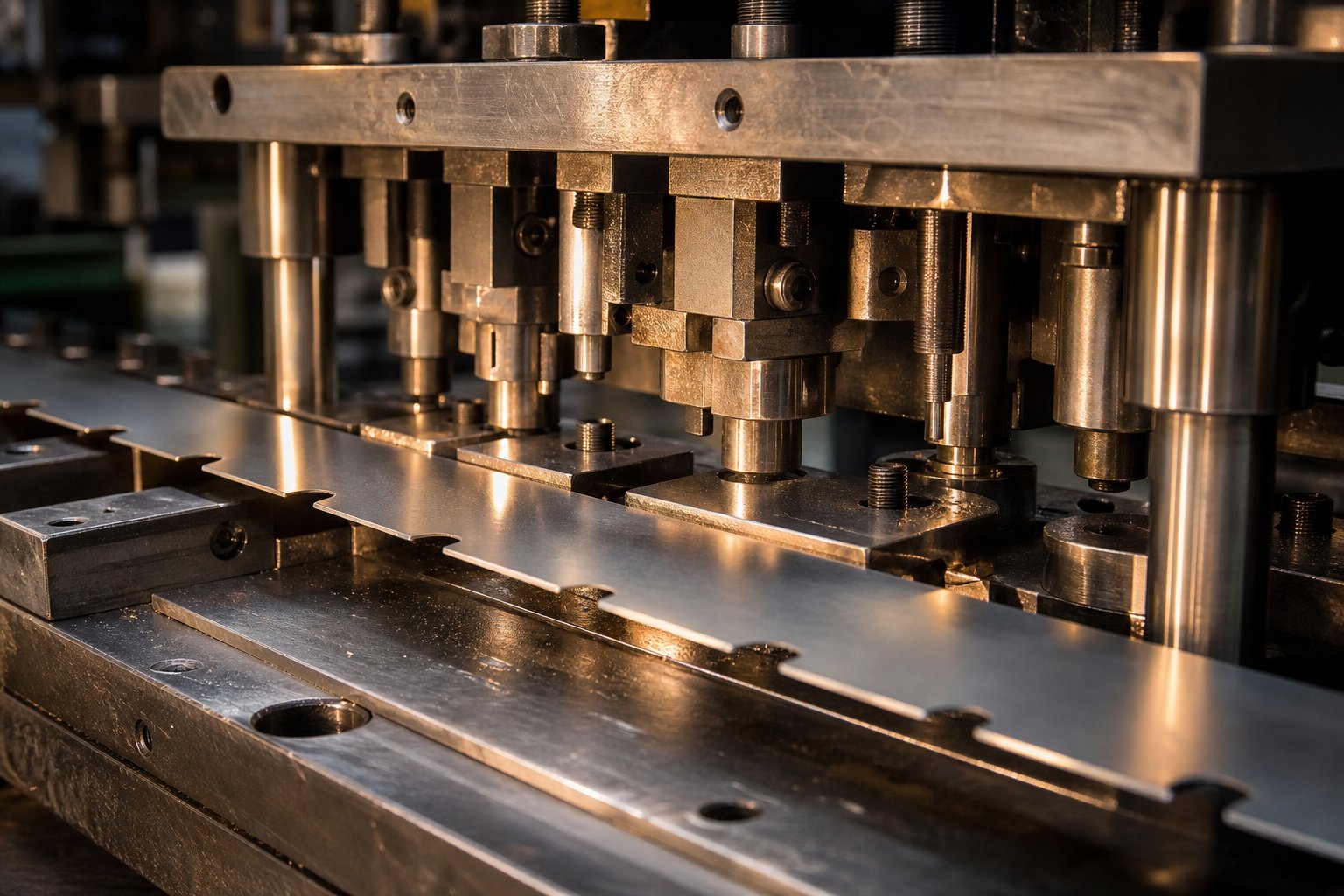
Understanding Bypass Notches in Sheet Metal Stamping Dies
A bypass notch, sometimes called a pitch notch or French notch, is a deliberate cutout or relief feature engineered into the carrier strip of a progressive stamping die. Its purpose is simple but critical: control exactly how far the strip advances between press strokes so that each station receives material in the correct position. Without this control mechanism, overfeeding or underfeeding the strip becomes a real possibility, and as any experienced tool and die professional knows, a single misfeed can trigger a die crash costing hundreds of times more than the material the notch consumes.
This article digs into the scientific basis behind negative and positive bypass notches in sheet metal stamping dies, bridging the gap between introductory technical stamping guides and expert-level die science. You will find metallurgical principles, mechanical relationships, and engineering decision frameworks rather than rules of thumb alone.
What Are Bypass Notches in Progressive Dies
Imagine a continuous coil of sheet metal feeding through a progressive die at high speed. The strip passes through multiple stations, each performing a specific cutting, forming, or drawing operation. For the finished part to meet dimensional tolerances, every station must engage the strip at precisely the same relative position, stroke after stroke.
A bypass notch provides that positional certainty. It is a small section of material cut away from one or both edges of the strip stock, typically at the first stations of the die. The resulting geometry creates a physical stop or registration feature that the strip contacts before the press cycles. As Art Hedrick notes in The Fabricator, overfeeding a progressive die without this stop can result in severe die damage and operator safety hazards.
Beyond preventing overfeeds, the notch also removes edge camber introduced during coil slitting. Camber makes smooth feeding nearly impossible on wide or thick materials, and by cutting a clean reference edge, bypass notches restore predictable strip behavior through the entire die length.
Why Strip Control Demands Precision Engineering
Strip control in a progressive die involves more than just feeding the correct distance. The carrier web holding parts together must maintain structural integrity, resist side bending, and accommodate vertical motion at forming stations. A poorly positioned or incorrectly sized notch weakens the carrier, causes buckling, or fails to engage the stop reliably.
Bypass notches serve three primary functions in this system:
- Strip registration - Providing a solid mechanical stop that prevents overfeeding and gives operators a definitive starting position during die setup, reducing the first-hit errors that cause the majority of progressive die damage.
- Scrap management - Removing edge camber and creating a clean reference surface, which eliminates loose scrap or half-hits that can jam downstream stations.
- Station-to-station progression control - Working in concert with pilot pins to ensure each part is located accurately, with the notch providing coarse positioning and pilots delivering final precision alignment.
Each function places specific geometric and metallurgical demands on the notch design. The depth, width, corner radii, and cutting clearance of the notch all interact with the material's mechanical properties to determine whether the strip feeds reliably or creates chronic production issues.
Negative Versus Positive Notch Fundamentals
The terms "negative" and "positive" describe the relationship between the notch geometry and the strip edge. A positive bypass notch removes material from the strip edge, creating a gap, relief, or inward cutout. The slug produced by this cut is ejected as discrete scrap. What remains is a strip with a reduced cross-section at each notch location.
A negative bypass notch takes the opposite approach. Rather than removing material entirely, it leaves a protruding tab or lance-like feature extending from the strip edge. This tab interlocks with a corresponding pocket or stop block in the die, providing a positive registration feature without producing a separate slug. One practical variation, described in industry literature as a lance and flange pitch stop, lances a small area in the strip and bends it downward to create a flange that both registers the strip and stiffens the carrier.
The choice between these configurations is never arbitrary. It depends on material type, strip width, thickness, production volume, and part complexity. Each configuration produces different stress distributions, fracture patterns, and wear characteristics in the tooling, all of which trace back to fundamental principles of shear mechanics and material behavior under load.
The Science of Shear and Fracture in Notch Cutting
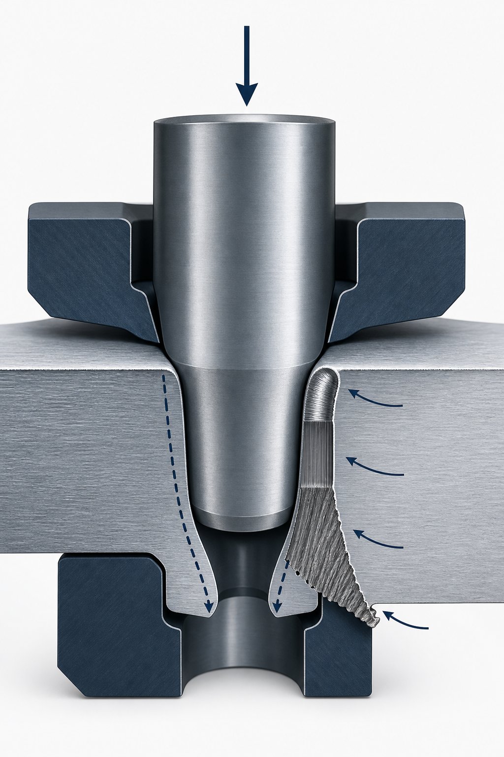
Every bypass notch begins as a controlled fracture. When the punch descends into the strip, the material does not simply split apart cleanly. It passes through a sequence of deformation phases, each governed by the relationship between the applied yielding force, the material's yield strength, and the geometry of the punch-die interface. Understanding these phases is what separates science-based notch design from guesswork.
Shear Mechanics During Notch Cutting
Picture the moment a notch punch contacts the strip surface. The material directly beneath the punch tip compresses elastically first, then plastically as localized stresses exceed the yield strength and yield point of the metal. This transition from elastic to plastic behavior follows the material's stress-strain curve (sometimes referenced as the s s curve in engineering shorthand), and it happens in microseconds at production stroke rates.
The cutting force required depends on the shear strength of the material, which typically falls between 60 and 80 percent of its ultimate tensile strength. As Art Hedrick explains, cutting a 10-inch-diameter blank from 0.100-inch mild steel requires approximately 78,000 lbs of force. Bypass notches involve far smaller perimeters, but the stress concentrations at the punch-die interface are proportionally intense because notch geometries often include tight corners and narrow widths.
At the punch edge, material is forced downward while the die opening constrains the surrounding strip. This creates a narrow shear band where plastic strain concentrates. The width of this band depends on clearance between punch and die. Insufficient clearance compresses the material laterally, increasing the yielding force needed for separation and generating excessive heat in the shear zone. Excessive clearance allows too much plastic bending before fracture, producing rolled edges and large burrs.
Fracture Zone Behavior in Positive and Negative Configurations
A completed cut edge exhibits four distinct zones, each revealing what happened mechanically during the cut:
- Rollover - The plastically deformed zone bent as cutting tools contact the sheet surface, visible as a rounded edge on the punch side.
- Burnish - The smooth, shiny band where the punch penetrated the material under compression before any fracture occurred. Surface stresses here compress into the cutting tool.
- Fracture - The rough, angled surface where cracks propagated through the remaining material thickness, completing the separation.
- Burr - Metal elongated and pushed out on the trailing edge of the cut, formed by the final tearing action.
Here is where positive and negative notch configurations diverge in behavior. In a positive notch, the punch removes a discrete slug from the strip edge. The fracture zone propagates outward, away from the carrier body and into the slug that becomes scrap. The strip retains the burnished surface on its remaining edge, which is generally the cleaner, more dimensionally stable zone.
In a negative notch, the geometry reverses. The cut defines a protruding tab that remains attached to the strip. Fracture propagation occurs inward, toward the strip body at the notch root. This means the carrier strip itself retains the fracture zone characteristics at the base of the tab feature.
Positive notches produce outward fracture propagation relative to the strip body, leaving cleaner edges on the carrier. Negative notches produce inward fracture propagation, concentrating the rougher fracture zone and associated microstructural damage at the notch root on the carrier strip side.
This distinction has real consequences. The shear affected zone (SAZ) behind each cut face contains work-hardened material with rotated grain structures. In dual-phase steels, this zone can extend 40 percent or more into the sheet thickness. When a negative notch places that damaged zone on the carrier strip, subsequent forming operations at downstream stations apply additional strain to already work-hardened material, raising the risk of edge cracking.
Grain Structure and Crack Propagation Direction
Sheet metal is not homogeneous at the microstructural level. Rolling during production elongates grains in the rolling direction, creating anisotropy in mechanical properties. When a notch punch initiates fracture, cracks preferentially follow paths of least resistance through the grain structure.
In materials where the rolling direction runs parallel to the strip feed direction (the most common orientation), crack propagation at notch corners tends to follow grain boundaries aligned with feed. For positive notches, this works in your favor because the crack travels into the scrap slug. For negative notches, the same tendency can drive cracks along the carrier strip edge, particularly at sharp notch root radii where yield stress concentrations are highest.
Force distribution at the punch-die interface also differs between configurations. A positive notch punch cuts into relatively free material at the strip edge. The material can deform slightly outward because one side is unconstrained. A negative notch punch, by contrast, cuts material that is constrained on both sides by the strip body. This bilateral constraint increases compressive stresses at the punch edge and accelerates wear, particularly when processing materials with high yield strength yield stress values like advanced high-strength steels.
The practical takeaway is that clearance rules developed for standard piercing operations do not translate directly to notch-specific geometry. Notch punches operate under asymmetric constraint conditions, and the fracture mechanics differ based on whether the retained geometry is the strip (positive notch) or the tab (negative notch). Each configuration demands clearance optimization tuned to its specific stress state, material properties, and the downstream demands placed on the cut edge.
Positive Bypass Notch Mechanics and Strip Behavior
A positive bypass notch physically removes a section of material from the strip edge, leaving behind a gap or relief where metal once existed. This sounds straightforward, but the mechanical consequences cascade through every downstream station. The strip becomes lighter, narrower at the notch location, and less resistant to bending. Whether those consequences help or hurt production depends entirely on how well the notch geometry matches the carrier design requirements.
How Positive Notches Remove Material from the Strip
During a positive notch punching stamping operation, a shaped punch descends through the strip edge and into a corresponding die opening. The punch perimeter defines the notch profile, typically a rectangular or trapezoidal shape cut inward from the strip edge. The separated material becomes a discrete scrap slug that falls through the die opening and is ejected downward into a scrap chute or container.
What remains on the strip is a clean-edged recess. This recess serves as the stop engagement feature. When the strip advances, the leading edge of the notch contacts a fixed stop block or hardened pin in the die, halting forward motion at exactly the correct progression distance.
Because one side of the cut is unconstrained (the open strip edge), the shear mechanics during this operation differ from a fully enclosed piercing operation. The material near the free edge can deform slightly outward during punch entry, which reduces the compressive stress at the punch face compared to a closed-perimeter cut. This means the stamping punching force required for a positive notch is slightly lower than for an equivalently sized hole punched away from any edge, all else being equal.
However, the open edge introduces a different concern. If the punch-to-die clearance is excessive on the edge side, the strip can deflect rather than shear cleanly, producing a rolled or torn edge rather than a defined fracture zone. Clearance relationships for positive notch punches follow standard cutting clearance rules but require tighter control on the free-edge side to compensate for the lack of material constraint.
Strip Rigidity and Feed Stability After Positive Notching
Every positive notch reduces the carrier strip's cross-sectional area at the notch location. Imagine looking at the strip from the end: where a full-width carrier has uniform resistance to bending, a notched carrier has periodic weak points where stiffness drops. The deeper the notch, the greater this reduction.
This matters because carrier strip strength must resist bending during the feeding process. As Art Hedrick notes, it takes roughly 10 percent of the part's weight to move it horizontally through the die. Multiply that by the number of stations, and the accumulated drag force acts on a carrier that has already been weakened at each notch point. If the remaining cross-section cannot support those feed loads without deflecting, the strip will buckle or skew laterally, creating stamping forming issues that ripple through every downstream station.
For narrow strips, this trade-off becomes critical. A notch that removes 30 percent of the strip width may reduce the carrier's moment of inertia enough to cause visible sag between stations. For wide strips with generous carrier webs, the same proportional notch has negligible impact on feed stability. The practical threshold depends on material thickness, material type, and the total number of progressions in the die.
Engineers compensate for this in several ways:
- Stiffening ribs - Adding embossed beads or formed ribs to the carrier strip before or after the notch station, increasing section modulus without adding material width.
- Dual-side notching - Placing shallower notches on both strip edges rather than one deep notch on a single side, distributing the cross-section reduction symmetrically and maintaining balanced feed behavior.
- Optimized notch depth - Limiting depth to the minimum needed for reliable stop engagement, typically 1.5 to 2.0 times material thickness, depending on feed accuracy requirements.
Punch Wear Patterns in Positive Notch Operations
Positive notch punches experience wear differently than standard piercing punches, and the reason traces back to constraint geometry. In a standard piercing operation, the punch cuts material surrounded on all sides by strip. The resulting compressive stresses are relatively symmetric around the punch perimeter. In a positive notch operation, the open edge side sees less compressive resistance while the strip-body side sees full constraint.
This asymmetry concentrates wear on the constrained faces of the punch, particularly the face cutting against the carrier strip body. Over thousands of strokes, this uneven loading produces a characteristic wear pattern: the constrained side develops edge rounding and micro-chipping earlier than the free-edge side. Die makers who maintain these tools know to inspect the carrier-side cutting edge first when troubleshooting burr growth.
Punch geometry also influences wear rate. Notch punches with sharp internal corners (at the bottom of the notch profile) concentrate stress at those points. Radii at internal corners are not optional; they are structural necessities. Tight corners wear fastest, and the EDM wire profiles used to manufacture these punches should incorporate minimum radii of 0.5 to 1.0 times material thickness at all internal transitions. Without adequate radii, stress risers on the punch accelerate edge breakdown and shorten maintenance intervals significantly.
Slug behavior in positive configurations adds another wear factor. Each stroke produces a discrete scrap slug that must eject cleanly through the die opening. If the slug sticks to the punch face on the return stroke (a condition called slug pulling), it can be carried back into the cutting area and crushed between the punch and strip on the next cycle. Slug pulling damages the punch face, mars the strip surface, and can trigger a die crash in severe cases. Positive notch geometries are somewhat more susceptible to slug pulling than standard piercing because the slug has a free edge that can spring back and grip the punch during retraction. Solutions include angular shear on the punch face, spring-loaded ejector pins, and vacuum-assisted slug removal systems.
Clearance selection for positive notch operations balances these competing demands: too tight increases cutting force and accelerates punch wear, too loose produces excessive burr and risks slug retention. The geometry-specific consideration for notch design is that clearance on the open-edge side can be slightly larger than on the constrained side, accounting for the asymmetric stress state without sacrificing edge quality on the carrier strip itself.
Negative Bypass Notch Mechanics and Material Flow
Positive notches sacrifice strip width for clean slug ejection and simple scrap management. Negative notches make the opposite trade. Instead of removing material from the strip edge, a negative notch leaves a protruding tab or lance-like feature extending outward from the carrier. No discrete slug is produced. No material is lost. The full strip cross-section remains intact at every progression point, and the tab itself becomes the registration mechanism that interlocks with corresponding pockets or stop blocks in the die.
This approach fundamentally changes the stress landscape of the carrier strip, the wear profile of the tooling, and the station-to-station clearance requirements. You keep your strip stiffness, but you inherit a new set of geometric constraints that must be managed through every downstream station.
How Negative Notches Preserve Strip Cross-Section
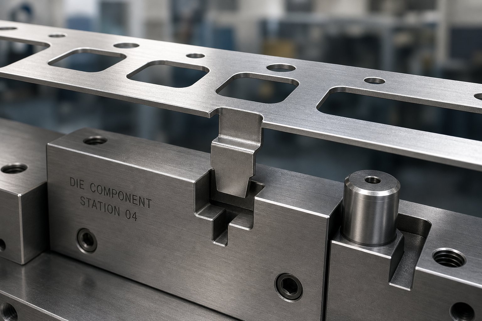
When you cut a negative notch, the punch and die create a partial separation, typically a lance cut on three sides of a small rectangular or trapezoidal area at the strip edge. The fourth side remains attached, acting as a hinge. The lanced tab is then bent downward (or occasionally upward) to form a flange that protrudes below or above the strip plane. As described in industry literature, a lance and flange pitch stop eliminates slug removal problems entirely because no separate piece of scrap is produced.
The carrier strip retains its full width. There is no periodic cross-section reduction, no localized drop in moment of inertia, and no weakened zone prone to buckling under feed loads. For narrow carriers or thin materials where rigidity is already marginal, this preservation of cross-section can be the deciding factor in notch type selection. The flanged tab also adds local stiffness by acting like a small structural rib, particularly when trapped in a bar lifter during feeding.
From a material utilization standpoint, negative notches consume zero additional strip width beyond what the carrier already requires. Positive notches demand extra material to accommodate the depth of the cutout without encroaching on the part blank. That difference, even if only a few millimeters per side, compounds across millions of parts into significant coil savings.
Registration Advantages of Protruding Tab Features
The bent tab created by a negative notch provides a three-dimensional registration feature rather than a simple edge stop. When the tab drops into a mating slot or pocket machined into the die shoe or a lifter rail, it captures the strip in both the feed direction and vertically. This dual-axis engagement resists strip lift during high-speed operation and prevents lateral skew more effectively than a flat edge bearing against a pin.
Consider what happens during setup. An operator threading a new coil into the die needs a definitive first-hit stop. A negative notch tab dropping into its pocket provides unmistakable tactile and visual feedback that the strip is seated correctly. This reduces the setup errors responsible for the majority of progressive die crashes, which typically occur in the first 10 hits during die set.
For large progressive dies processing wide or thick coil material, pilot pins alone often cannot register the strip with sufficient authority before the press cycles. Negative notch tabs combined with pilots create a two-tier registration system: the tab provides coarse positioning and overfeed prevention, while the pilot pins deliver final precision alignment measured in thousandths of an inch.
Clearance and Station Interference Considerations
The mechanical advantage of a negative notch comes with a geometric cost. Every protruding tab must physically clear every downstream die component as the strip advances. Lifter rails, cam drivers, forming punches, pad surfaces, and stripper plates all must be relieved or slotted to accommodate the tab passing through.
In a die with 15 or 20 stations, this clearance requirement multiplies rapidly. Each station needs a relief pocket or channel matching the tab's footprint, and those reliefs must account for the tab's bent angle plus any springback that might alter its actual protruding height. If a tab catches on a downstream component during feed, the strip jams, and the next press stroke lands on misregistered material. The result is the same die crash that the notch was designed to prevent.
Stress distribution at the notch root presents the other critical consideration. The lance cut that defines the tab creates a sharp geometric discontinuity on the strip body side. Stress concentrates at this root radius in a pattern governed by the ratio of radius to material thickness. A root radius smaller than 0.5 times material thickness can generate stress concentration factors exceeding 3.0, meaning localized stresses at the notch root reach three times the nominal stress in the surrounding carrier.
This matters because the cutting and bending action at the notch root produces significant work hardening in that zone. The material at the root has been plastically deformed during the lancing operation, and the subsequent bending of the tab intensifies strain hardening further. In low-carbon steels, this deformation hardening might increase local hardness by 20 to 40 percent compared to the base material. The zone becomes harder, less ductile, and more prone to crack initiation under additional loading.
When the strip passes through subsequent forming or bending stations, the work hardened notch root experiences additional tensile or compressive strain. If a forming operation applies bending stress across the carrier near the notch location, the already strain hardened root acts as a crack initiation point. The reduced ductility means the material reaches its fracture limit sooner than the surrounding base metal, potentially splitting the carrier during production.
Engineers manage this risk through several approaches:
- Generous root radii - Specifying minimum radii of 1.0 to 1.5 times material thickness at the lance root, reducing peak stress concentration and distributing plastic strain over a larger volume.
- Notch positioning away from form zones - Locating the notch at carrier regions that do not undergo subsequent forming, ensuring the work hardened root never sees additional strain from bending or drawing operations.
- Material grade selection - Choosing materials with higher elongation capacity that can absorb the deformation hardening at the root and still retain sufficient ductility for downstream operations.
- Controlled tab bend angle - Limiting the downward bend to the minimum angle needed for reliable registration, reducing the total plastic strain imposed at the root during the lancing and forming sequence.
Negative notches trade station clearance complexity for superior strip control and material utilization. The carrier retains full cross-section stiffness and zero material is wasted, but every downstream station must accommodate the protruding tab, and the work hardened notch root demands careful geometric design to avoid becoming a crack initiation site.
The interplay between notch root metallurgy and downstream forming requirements makes negative notch design inherently more sensitive to material properties than positive notch design. Materials with limited elongation or aggressive strain hardening rates amplify the risks at the notch root, shifting the engineering calculation toward positive configurations in some applications. How specific material grades influence that calculation is where the next layer of design science comes into play.
How Material Properties Influence Notch Design Selection
A notch root that behaves predictably in mild steel can become a crack initiation site in dual-phase 980. A clearance that produces clean edges in aluminum leaves secondary shear marks on stainless. Material grade does not merely tweak bypass notch performance; it redefines the entire design envelope. The elastic modulus, elongation capacity, yield strength of steel or alloy, and work hardening rate each play distinct roles in determining whether a notch operates reliably or fails prematurely.
The relationship between yield strength vs tensile strength is particularly revealing. Materials with a low ratio between these values (meaning the material work hardens significantly before reaching ultimate strength) tolerate notch root deformation better because the surrounding material can absorb strain energy without immediate fracture. Materials with a high ratio, where yield and tensile values are close together, offer almost no deformation buffer. The strip either holds or it cracks.
Mild Steel and Low-Carbon Alloy Notch Behavior
Low-carbon steels with yield strengths below 300 MPa and elongation values exceeding 30 percent are the most forgiving materials for bypass notch operations. Their high ductility means the shear affected zone at the notch root remains relatively small, and work hardening at cut edges is moderate. The modulus of elasticity of steel in this category sits around 200 GPa, providing predictable elastic recovery and minimal springback at the notch tab.
For mild steel, both positive and negative notch configurations perform well. Edge quality after cutting shows a clearly defined burnish zone with a smooth transition into the fracture zone, the ideal condition for edge ductility. Clearances in the range of 5 to 10 percent of material thickness produce acceptable results, and burr height serves as a reliable indicator of when tooling needs resharpening.
Work hardening at the notch root in mild steel increases local hardness but rarely exhausts the material's remaining elongation capacity. A negative notch root that has been lanced and bent still retains enough ductility to survive downstream forming operations without cracking. This forgiving behavior is why negative notches originated in low-carbon steel progressive die applications and why many traditional design guidelines assume mild steel properties as the baseline.
AHSS and High-Strength Material Challenges
Advanced high-strength steels change the calculation dramatically. Dual-phase (DP), complex phase (CP), and martensitic steels offer tensile strengths from 600 MPa to well over 1400 MPa, but their elongation values drop to single digits in the highest strength grades. Research published by the AHSS Application Guidelines confirms that these grades exhibit high degrees of work hardening during shearing, creating higher strength and hardness at cut edges with significantly reduced edge ductility.
The elastic modulus of steel remains essentially constant across these grades (approximately 200 to 210 GPa), so springback behavior at the notch is governed primarily by the ratio of yield strength to elastic modulus rather than any change in stiffness itself. Higher yield strengths produce greater elastic recovery after bending, meaning negative notch tabs spring back more aggressively and require tighter tolerances on pocket geometry to maintain reliable registration.
Edge quality in AHSS behaves counterintuitively. These materials produce less rollover and smaller burrs than mild steel because they fracture with less plastic deformation. However, the sheared edge contains hard martensitic islands that act as crack initiators. DP and TRIP steels are particularly vulnerable because hard particles at cut edges further reduce allowable edge stretch. For negative notch roots in AHSS, this combination of limited elongation and microstructural stress risers creates unpredictable fracture behavior.
Clearance requirements increase significantly. Where mild steel uses 5 to 10 percent, AHSS grades may require 14 to 16 percent or higher as tensile strength exceeds 1400 MPa. A study on CP1200 steel demonstrated that increasing clearance from 10 to 15 percent led to significant improvement in edge performance, reinforcing that historical 10 percent rules do not apply to these materials. Positive notches become preferable in many AHSS applications because the fracture zone propagates into the scrap slug rather than concentrating at the carrier strip root, preserving what limited edge ductility remains for downstream operations.
Aluminum and Stainless Steel Special Considerations
Aluminum alloys introduce a different set of challenges. Their elastic modulus is roughly one-third that of steel (approximately 70 GPa), which means strip springback after notching follows entirely different magnitudes. A negative notch tab in aluminum springs back roughly three times more than in steel at equivalent yield strength, making tab-to-pocket registration less precise unless compensated with overbend or tighter pocket tolerances.
As MetalForming Magazine notes, many automotive grades of aluminum form like a 100,000-PSI yield-strength steel but with only about two-thirds the stretching ability. Their work hardening behavior and surface topography differ enough from steel that standard die design tables should not be applied directly. Notch edge quality in aluminum tends toward gummier, less defined fracture zones because the material's ductility allows more deformation before separation. Slug pulling risk increases in positive notch configurations due to aluminum's tendency to adhere to punch surfaces under compression.
Stainless steels, particularly austenitic grades like 304 and 316, combine high work hardening rates with relatively high elongation. Forming stainless requires roughly twice the press power of mild steel due to this aggressive work hardening. At the notch root of a negative configuration, the lancing and bending operation can locally double the hardness of the base material. Despite this, stainless steels maintain enough residual ductility that negative notch roots rarely crack during subsequent forming, provided root radii are generous.
The critical issue with stainless is clearance sensitivity. A 10 percent die clearance, standard for mild steel, produces the worst possible burr height in stainless according to Dayton Progress research. Optimized clearances for stainless notch cutting typically fall between 12 and 15 percent, balancing edge quality against the higher cutting forces that accelerate punch wear.
| Material Type | Recommended Notch Type Preference | Typical Clearance Range (% of thickness) | Work Hardening Sensitivity | Edge Quality Characteristics | Strip Control Considerations |
|---|---|---|---|---|---|
| Mild Steel (YS < 300 MPa) | Either positive or negative | 5-10% | Moderate; edges retain ductility | Defined burnish and smooth fracture; burr height is a reliable wear indicator | Forgiving; both configurations provide reliable registration |
| AHSS / DP / CP (YS 350-1000+ MPa) | Positive preferred for high-strength grades | 10-16%+ (increases with tensile strength) | High; shear affected zone is hard and brittle | Less rollover and burr, but edge microcracking and secondary shear risk | Negative notch roots prone to cracking; positive avoids carrier damage |
| Martensitic Steel (YS > 1000 MPa) | Positive strongly preferred | 14-21% | Very high; minimal remaining elongation at edges | Abrupt fracture with almost no rollover; chipping risk on tight clearance | Strip springback makes negative tab registration unreliable; carrier too brittle at notch root |
| Aluminum Alloys (5xxx/6xxx series) | Positive preferred; negative requires springback compensation | 8-12% | Low to moderate; grade-dependent | Gummy fracture zones; slug adhesion to punch surface | Low elastic modulus causes large springback on negative tabs; higher slug pulling risk on positive |
| Stainless Steel (Austenitic 304/316) | Either; negative works well with generous radii | 12-15% | Very high; up to 2x local hardness increase | Clean edges at optimized clearance; worst burr at 10% clearance | High feed forces require stiff carriers; negative notch preserves stiffness advantage |
The table above highlights a directional relationship: as material strength increases and elongation decreases, the engineering preference shifts toward positive notches. The reasoning is consistent. Positive configurations push fracture damage into disposable scrap rather than concentrating it on the carrier strip where it compounds through subsequent forming operations. Materials with ample ductility and moderate work hardening can tolerate negative notch roots without issue; materials near their formability limits cannot.
One additional factor deserves attention. The modulus of elasticity of steel remains nearly constant regardless of grade, but aluminum's much lower modulus creates a fundamentally different springback environment. Engineers accustomed to designing negative notch tabs for steel discover that the same geometry in aluminum yields unpredictable tab heights, inconsistent pocket engagement, and chronic registration drift. Compensating with deeper pockets or angled capture features adds complexity that may not justify the material savings from a negative configuration.
These material-driven constraints explain why experienced die designers begin every bypass notch decision by examining the material data sheet. Yield strength, ultimate tensile strength, total elongation, and n-value (work hardening exponent) together define the design window. Outside that window, even perfectly machined tooling with ideal clearances will produce edges that crack, tabs that spring out of registration, or carriers that split at the first downstream forming station. Geometry parameters and die layout decisions follow from, rather than precede, this material analysis.
Notch Geometry Parameters and Progressive Die Layout
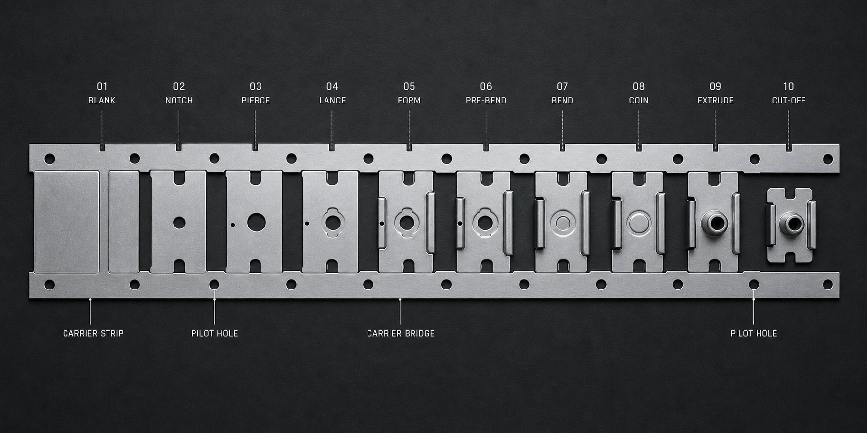
Material properties define the design window. Geometry parameters fill it. The depth, width, corner radii, and angular relationships of a bypass notch translate metallurgical constraints into physical tooling dimensions that either deliver reliable strip control or introduce chronic production problems. Each parameter interacts with material thickness, strip width, and progression distance in ways that demand coordinated decisions rather than isolated specifications.
Notch Depth and Width Relationships to Strip Geometry
Notch depth is the distance the cutout or tab extends inward from the strip edge. Deeper notches provide more positive mechanical engagement with the stop block or pocket, making overfeed physically impossible even under aggressive feed acceleration. But depth comes at a cost. In positive configurations, every additional millimeter of depth removes carrier cross-section, reducing the moment of inertia that keeps the strip stable during metal forming operations at downstream stations. In negative configurations, greater depth means a longer lanced tab that requires more clearance through every subsequent die component.
The practical guideline for positive notch depth falls between 1.5 and 3.0 times material thickness. Below 1.5t, the engagement is too shallow to reliably arrest strip motion before the press cycles. Above 3.0t on narrow carriers, the remaining cross-section may lack the stiffness to resist feed-direction buckling. For negative notches, tab length (the functional equivalent of depth) typically ranges from 2.0 to 4.0 times material thickness, with the longer dimension needed to ensure the bent tab seats fully in its registration pocket.
Notch width is constrained by progression distance, the fixed dimension that defines how far the strip advances per press stroke. The notch must be narrow enough to fit within one progression pitch without overlapping the next station's features, yet wide enough to provide adequate stop surface area. A common starting point is notch width between 40 and 60 percent of progression distance, leaving sufficient bridge material on both sides of the notch to maintain carrier integrity between progressions. As strip layout design principles note, the bridge thickness between features should be at least 1.25 to 1.5 times material thickness to prevent scrap twisting and carrier failure.
Strip width determines whether single-side or dual-side notching is appropriate. Narrow strips (typically under 50 mm for standard gauge materials) benefit from single-side notching to preserve maximum carrier width on the opposite edge. Wide strips often use dual-side notching with shallower depths on each edge, distributing the cross-section reduction symmetrically and preventing the lateral feed drift that occurs when asymmetric forces act on the carrier during progression.
Corner Radius Design and Stress Concentration Management
Sounds minor? Corner radii at notch transitions are among the most consequential dimensions on the entire strip layout. A sharp internal corner on a positive notch concentrates stress in the punch tooling, accelerating wear at that point. A sharp root radius on a negative notch concentrates stress in the strip material, creating crack initiation sites that can propagate under downstream forming loads.
The stress concentration factor (Kt) at a notch corner follows a relationship governed by the ratio of radius to depth. For a rectangular notch with a root radius r and depth d, Kt increases rapidly as r/d drops below 0.25. At r/d = 0.1, concentration factors can exceed 4.0, meaning localized stress reaches four times the nominal value in the carrier. For materials with limited elongation, this level of concentration exceeds the fracture strain at the root before the strip even reaches the first forming station.
Practical radius specifications depend on both the material's elastic modulus metals exhibit and their elongation capacity:
- Mild steel - Minimum internal radius of 0.5t at notch corners; 1.0t at negative notch roots where subsequent forming occurs nearby.
- AHSS grades - Minimum 1.0t at all internal corners; 1.5t or greater at negative notch roots due to limited edge ductility.
- Aluminum alloys - Minimum 0.75t at internal corners; larger radii needed on negative roots to accommodate the material's tendency toward gummy fracture propagation.
- Stainless steel - Minimum 1.0t at internal corners to compensate for aggressive work hardening at the cut edge.
These radii also affect the tooling. Punch corners with radii below 0.3 mm in hardened tool steel develop micro-chipping within the first 50,000 strokes on most production materials. EDM wire-cut profiles should specify radii as explicit dimensions rather than relying on the natural wire radius to define the corner, because wire diameter erosion during cutting can produce inconsistent radii that look adequate on paper but fail in practice.
Pilot Placement Interaction with Notch Positioning
Bypass notches and pilot pins serve the same goal, accurate strip positioning, but at different precision levels. The notch provides coarse control, preventing gross overfeeds and establishing a repeatable starting position for each press stroke. Pilot pins provide fine control, correcting for the small positional errors that accumulate from feed roll slippage, material springback, and thermal expansion of the strip during high-speed runs.
Their spacing must be coordinated. If a pilot pin is located too close to a bypass notch, the two features compete for positional authority. The notch arrests the strip at one position while the pilot attempts to shift it to a slightly different position as it enters the hole. This conflict creates shear stress on the pilot pin, elongation of the pilot hole, and inconsistent part positioning that shows up as dimensional scatter in the finished components.
The standard approach places the bypass notch at station one (or the first cutting station) and pilot holes at stations two and three. This sequence ensures the notch establishes coarse position first, then pilots refine it before any critical forming or dimensioning operations begin. For dies with many stations, additional pilots are placed at intervals of every three to five progressions, but always offset from notch locations by at least one full progression pitch.
As progressive die design guidelines recommend, if two sets of pilots are required, both should be punched at the same station to maintain their relative accuracy. Pilot holes punched at different stations inherit the cumulative positioning error of every progression between them, degrading the very precision they are meant to provide.
The sequential design decision process that coordinates all these parameters follows a logical hierarchy:
- Determine progression distance - This is fixed by part geometry and defines the maximum available space for all strip features including notches, pilots, and carrier bridges.
- Establish strip width - Calculated from part blank size plus carrier web requirements plus any edge trim allowance, setting the total cross-section available for notch engagement.
- Select notch type based on material and geometry - Material properties (covered in the preceding section) combined with strip width and carrier stiffness requirements dictate whether positive, negative, or no notch is appropriate.
- Define notch dimensions - Depth, width, and corner radii are specified within the constraints established by steps one through three, balancing engagement reliability against strip integrity.
- Coordinate pilot placement - Pilot hole locations are chosen to complement notch positioning without conflict, spaced to correct feed error accumulated after the notch station.
Strip layout optimization shifts meaningfully depending on which notch type is selected. Positive notches consume strip width, material nesting software for length of material calculations must account for the notch depth when computing minimum strip width. A 2 mm deep positive notch on each side adds 4 mm to the total coil width required, which across a production run of millions of parts translates into measurable material cost. Modern nesting algorithms factor this in automatically, but the input parameters must reflect the actual notch geometry rather than a generic allowance.
Negative notches consume zero additional strip width but add complexity to die construction. Every station needs relief geometry for the protruding tab, increasing machining time and cost during die build. The trade-off is economic: negative notches save material across the production run while positive notches save tooling cost during die construction. Which factor dominates depends on production volume, material cost per kilogram, and die amortization schedule.
These geometric parameters do not exist in isolation. Each dimension cascades into decisions about strip layout, pilot strategy, scrap handling system design, and die maintenance intervals. The next logical step is organizing these interacting variables into a structured decision framework that helps engineers choose the right notch configuration before committing to steel.
Decision Framework for Notch Type Selection
Geometry parameters and material properties define what is possible. A decision framework defines what is practical. Engineers facing a new progressive die project rarely struggle with calculating notch depth or selecting clearance percentages once the notch type is chosen. The harder question comes earlier: should this die use positive notches, negative notches, or no bypass notches at all? The answer depends on at least seven interacting variables, and getting it wrong cascades into strip layout revisions, pilot strategy changes, and maintenance headaches that persist for the life of the tool.
What follows is a structured approach to that decision, organized around the factors that experienced tool and die engineers evaluate, sometimes intuitively, when committing to a notch configuration.
When to Use Positive Bypass Notches
Positive notches earn their place in dies where clean scrap ejection, material strength limitations, and straightforward die construction take priority over strip stiffness and material savings. Imagine a scenario: you are running AHSS at 1.2 mm thickness on a narrow carrier, feeding through 12 stations at 200 strokes per minute. The material's yield stress leaves almost no room for edge strain at a negative notch root. A positive configuration pushes all fracture damage into disposable scrap, preserving what little edge ductility remains on the carrier.
Positive notches are also the default choice when:
- The material has yield stress of steel exceeding 600 MPa, where notch root cracking risk outweighs material savings from a negative configuration.
- The die has fewer than eight stations, making the downstream clearance advantages of negative notches less significant.
- Slug removal infrastructure is already built into the die design (scrap chutes, vacuum systems, through-bolster removal).
- Strip width provides ample carrier cross-section, meaning the material removed by the notch does not critically weaken feed stability.
- The feed system relies on an inductive proximity sensor or other electronic die protection that confirms strip position, making the physical registration of a negative tab less critical.
The trade-off is material consumption. Every positive notch slug is purchased coil stock that becomes scrap. On a die producing 5 million parts per year, even a small notch adds measurable material cost. Whether that cost is justified depends on how it compares to the risk-weighted cost of carrier cracking, die crashes, or the added machining required for negative notch clearances.
When to Use Negative Bypass Notches
Negative notches shine when strip stiffness is non-negotiable, material utilization targets are aggressive, and the material itself can tolerate the work hardening imposed at the notch root. Think of a wide carrier in mild steel running through 20 stations with forming operations that apply bending loads near the strip edges. A positive notch at that location weakens the carrier right where it needs strength most. A negative notch preserves the full cross-section and provides superior three-dimensional registration.
Conditions favoring negative notches include:
- Narrow strip widths where removing material for a positive notch would reduce carrier stiffness below the threshold for reliable feeding.
- Materials with elongation above 25 percent and moderate work hardening rates that tolerate the strain imposed during tab lancing and bending.
- High station counts where the cumulative feed error from coil feeder imprecision demands robust mechanical stops rather than sensor-based detection alone.
- One-sided carrier designs where the tab can be trapped in a bar lifter, simultaneously providing registration and preventing lateral carrier deflection.
- Production volumes high enough that the material savings from eliminating positive notch slugs justify the added die construction cost for tab clearance pockets.
The critical constraint is downstream clearance. Every die station must accommodate the protruding tab, and every maintenance cycle must verify that tab pockets remain clean and undamaged. In dies with complex cam systems or tight vertical clearances, the physical space for tab relief may simply not exist.
When No Bypass Notches Are Required
Not every progressive die needs a bypass notch. When conditions are right, eliminating notches entirely saves material, simplifies die construction, and removes one more maintenance item from the tooling schedule. The question is whether your process can maintain reliable feeding and positioning without the mechanical backup a notch provides.
No-notch operation becomes viable when:
- The coil feed system delivers positioning accuracy within 0.05 mm or better, verified through documented capability studies.
- Incoming material has minimal edge camber (typically slitting from a high-quality service center with post-slit edge conditioning).
- Die protection sensors are installed, properly calibrated, and never bypassed during setup.
- Operators and setup personnel are highly trained on progressive die feeding and misfeed recognition.
- Part geometry includes features at early stations (perimeter trims or large pilot holes) that inherently prevent overfeed by creating natural stops.
As Art Hedrick notes, if your incoming material has no severe edge camber, your personnel are highly skilled, misfeeds are rare, and die protection always works properly, you may not need a notch. But meeting all those criteria simultaneously is uncommon. Most die builders design a notch into the tool and leave the decision of removing it to the stampers who know their operation's capabilities.
The risk calculus is asymmetric. The material cost of a pitch notch over millions of parts might total a few thousand dollars. A single die crash from overfeeding can cost hundreds of thousands in repair, downtime, and missed production schedules. For critical tooling where uptime matters, the conservative approach favors including a notch unless there is a documented, process-verified reason to omit it.
Notch Type Selection Criteria Matrix
The following table consolidates the decision factors into a comparative framework. Each row represents a variable that influences the selection, and each column shows how that variable shifts preference toward a specific configuration.
| Decision Factor | Positive Notch Preferred | Negative Notch Preferred | No Notch Viable |
|---|---|---|---|
| Strip width | Wide strips (greater than 80 mm) with ample carrier cross-section | Narrow strips (under 50 mm) where material removal critically weakens the carrier | Any width, provided feed system accuracy is verified |
| Material thickness | Thin materials (under 0.8 mm) where slug ejection is manageable | Medium to thick materials (0.8-3.0 mm) where tab stiffness is reliable and lancing force is moderate | Medium thickness with predictable feed behavior and minimal camber |
| Material strength class | High-strength (yield stress above 500 MPa); AHSS, DP, martensitic grades with limited edge ductility | Low to moderate strength (yield stress below 400 MPa); mild steel, HSLA with elongation above 25% | Any strength class, provided die protection is comprehensive |
| Production volume | Low to moderate volumes where die simplicity outweighs per-piece material cost | High volumes (millions of parts) where cumulative material savings justify added die construction cost | Low volumes with experienced operators and short runs |
| Number of die stations | Fewer than 10 stations where tab clearance complexity is manageable either way | 10 or more stations where cumulative feed error demands robust mechanical registration | Short dies (under 6 stations) with minimal error accumulation |
| Part geometry complexity | Simple geometries with limited forming near the carrier edge | Complex forming near carrier edges where full cross-section stiffness is essential | Geometries that create natural overfeed stops (large cutouts, perimeter trims at early stations) |
| Feed system precision | Standard servo feeds with 0.1 mm or better accuracy | Older mechanical feeds or high-speed applications where inertia causes overshoot | High-precision servo systems with documented capability below 0.05 mm, combined with active electronic die protection |
You will notice that no single factor dictates the outcome in isolation. A narrow strip in mild steel running at high volume points strongly toward negative notches. The same narrow strip in DP 980 at moderate volume reverses the recommendation entirely. The tensile modulus steel exhibits does not change between these grades, but the fracture behavior at the notch root shifts so dramatically that the entire configuration must follow.
Notch selection is never an isolated decision. It cascades into strip layout width calculations, pilot strategy and spacing, scrap handling infrastructure, downstream station clearance requirements, and die maintenance intervals. Changing the notch type after die design has progressed beyond concept stage typically requires reworking the entire strip layout.
This cascading effect is why the decision framework matters most at the earliest design stage, before strip width is committed to coil purchase specifications, before die shoe dimensions are finalized, and before station sequencing locks in clearance envelopes. Engineers who defer the notch type decision often discover that their strip layout assumptions embedded a choice implicitly, one that may not align with the material or production requirements that emerge during detailed design.
A structured framework removes ambiguity. It translates the interplay between material science, die geometry, and production economics into a repeatable evaluation that delivers consistent results across projects. But frameworks address the design intent. What happens when that intent meets production reality and something goes wrong? Strip misfeeds, slug pulling, premature wear, and carrier failures each trace back to specific breakdowns in the scientific relationships covered throughout this article, and diagnosing them requires connecting symptoms to root causes through the same principles that governed the original design.
Troubleshooting Bypass Notch Failure Modes
A well-designed bypass notch can run millions of cycles without incident. A poorly designed one announces itself within the first thousand strokes through misfeeds, burrs, pulled slugs, or cracked carriers. The frustrating part? These symptoms often look identical on the press floor regardless of whether the root cause is geometric, metallurgical, or clearance-related. Separating one from another requires connecting visible evidence back to the fracture mechanics and material behavior that govern notch performance.
What follows is a systematic breakdown of the five most common bypass notch failure modes, their scientific root causes, and the diagnostic steps that lead to lasting corrections rather than temporary patches.
Strip Misfeed and Inadequate Notch Engagement
When the strip advances too far or not far enough, every downstream station processes material in the wrong position. Holes land off-center, bends form at incorrect locations, and dimensional scatter increases until parts fail inspection. In severe cases, the misfeed causes a full die crash, damaging punches, die blocks, and guide systems simultaneously.
Inadequate notch engagement is the most common culprit. The notch exists to arrest strip motion at a precise point. If the engagement surface is too shallow, worn, or geometrically mismatched to the stop block, the strip overshoots before the press cycles. Progressive die troubleshooting research confirms that strip positioning instability is often the earliest failure signal, appearing before visible part defects emerge.
The root cause connects directly to the stress and deformation principles covered earlier. A positive notch that has lost depth through cumulative punch wear no longer creates the full engagement pocket geometry. The stop block contacts a shallower surface, and under feed acceleration forces, the strip momentum overcomes the reduced contact area. For negative notches, springback at the tab root is the typical mechanism. If the material's yield limit of steel or alloy exceeds the original design assumption, the tab does not bend to its intended angle, reducing how deeply it seats in the registration pocket.
- Check notch depth against original specification - Measure the actual remaining engagement depth with pin gauges or optical comparator. Compare to the minimum 1.5t threshold for reliable stop contact.
- Inspect the stop block surface - Peening, material buildup, or wear on the stop face reduces effective engagement even when the notch itself is correct.
- Verify feed release timing - If the feeder releases the strip too late, the pilots attempt to register material that has not fully seated against the notch stop, creating positional conflict and inconsistent advancement.
- Measure tab springback on negative notches - Compare the actual bent angle to design intent. Materials with higher yield strength produce more elastic recovery, and the tab may have sprung back beyond the pocket capture range.
- Evaluate strip camber - Edge camber from coil slitting can prevent the strip from tracking straight, causing the notch to miss the stop block laterally even when feed distance is correct.
The key diagnostic distinction is whether the misfeed is consistent (pointing to a geometry or setup error) or intermittent (pointing to dynamic factors like feed timing, strip vibration at speed, or thermal expansion during extended runs). Consistent misfeeds trace to static dimensions. Intermittent ones trace to process dynamics that only manifest under production conditions.
Slug Pulling and Burr Formation at Notch Edges
Slug pulling in positive notch configurations is one of the most damaging failure modes in progressive stamping. When a scrap slug adheres to the punch face during withdrawal and gets carried back into the working space, it can crush between punch and strip on the next stroke, damaging the die surface, marring the part, or triggering a cascade of jammed stations. As Art Hedrick explains, a single pulled slug can cripple production and damage every station in the tool.
The science traces to vacuum mechanics and clearance geometry. During cutting, the slug develops curvature as it separates from the strip. Air trapped between the curved slug and the flat punch face creates a vacuum pocket. The metal around the punch perimeter forms a tight seal during shearing, and on withdrawal, this seal prevents the slug from releasing. Heavy lubricants intensify the sealing action. Positive bypass notches are somewhat more susceptible than standard piercing operations because the slug has a free edge that can flex and grip the punch during retraction.
Large cutting clearances compound the problem. With smaller clearances, the slug is forced into compression during cutting and decompresses after separation, creating an interference fit that holds it in the die matrix. With larger clearances, the slug remains slightly undersized relative to the matrix opening and can be pulled freely with the punch. The stamping tool material choice also matters: magnetized punch surfaces from surface grinding attract ferrous slugs unless components are properly demagnetized after sharpening.
Burr formation at notch edges creates a different but related problem. Excessive burrs on the notch cut edge interfere with downstream forming operations by acting as stress risers during bending, creating surface scratches on die components, and preventing the strip from lying flat against pressure pads. What is yield strength of the material relative to the forces at play? When punch edges dull, the cutting action transitions from clean shearing to tearing. The material stretches beyond its yield strain steel can accommodate before separating, producing elongated burr projections rather than clean fracture.
- For slug pulling - Vent the punch center with an air hole to break vacuum. Install spring-loaded ejectors in punches large enough to accept them. Consider reverse-taper die buttons that hold slugs in compression. Demagnetize all components after grinding.
- For excessive burr - Measure punch-to-die clearance and compare against material-specific recommendations. Inspect cutting edges for rounding or micro-chipping. Establish sharpening intervals based on stroke count rather than waiting for visible burr growth.
- For both conditions simultaneously - This combination usually indicates advanced punch wear. The dulled edge produces larger burrs while the increased friction between worn surfaces creates stronger vacuum adhesion. A preventive sharpening program based on actual stroke counts helps maintain stable cutting loads and reduces both slug pulling and burr formation before they reach critical levels.
Premature Die Wear and Maintenance Implications
Bypass notch punches and die openings experience concentrated wear for reasons rooted in their asymmetric geometry. Unlike a standard round piercing punch that distributes shearing forces uniformly around its perimeter, a notch punch has constrained faces (cutting against the carrier body) and unconstrained faces (cutting at the open strip edge). This imbalance means one side of the tooling works harder than the other, every stroke.
The constrained side experiences higher compressive loading because the surrounding carrier strip resists deformation. Over hundreds of thousands of cycles, this face develops edge rounding and micro-chipping first. The unconstrained side, cutting into free material, wears more slowly. The result is progressive clearance asymmetry: the side cutting against the carrier gradually opens up while the free-edge side remains tighter. Dimensional drift in notch geometry follows.
Material properties accelerate this pattern. Processing materials near their yield limit of steel rating, particularly AHSS grades, dramatically increases punch loading per stroke. A notch punch cutting DP 980 at 1.5 mm thickness absorbs roughly twice the shearing force of the same punch cutting mild steel at identical thickness. That force differential translates directly into accelerated edge breakdown, more frequent sharpening, and shorter overall punch life. The stamping tool material itself must match the application: carbide inserts become necessary in high-load notch stations where conventional tool steel degrades too quickly.
Strip buckling from over-weakened carriers represents the structural failure mode. When positive notches remove too much cross-section, or when multiple notch stations compound the weakening effect, the carrier loses sufficient stiffness to resist feed-direction compressive loads. The strip buckles between stations, lifts off the die surface, and jams against downstream components. The root cause is mechanical: the carrier's moment of inertia has dropped below the threshold needed to support the cumulative drag forces from all stations acting on it simultaneously.
- Monitor punch wear asymmetry - During scheduled maintenance, inspect the carrier-side cutting edge first. If rounding exceeds 0.02 mm while the free-edge side remains sharp, resharpening is overdue.
- Track sharpening intervals against material grade - Establish baseline stroke counts for each material type. AHSS and stainless steel applications typically require sharpening at 40 to 60 percent of the intervals acceptable for mild steel.
- Verify carrier stiffness after notching - If strip buckling appears during production, calculate the remaining carrier moment of inertia at the notch location and compare against the feed force requirements for the total number of stations.
- Evaluate stamping tool material selection - Persistent premature wear despite correct clearance and sharpening suggests the punch material cannot sustain the loading conditions. Upgrading from D2 tool steel to carbide or applying TiAlN coatings can extend life by 3 to 5 times in demanding applications.
The common thread across all these failure modes is that symptoms appearing at one location in the die often originate from decisions made elsewhere, during design, material selection, or setup. As die science research emphasizes, thousands of variables interact within a stamping process, and discovering how they connect is essential for identifying root causes rather than chasing symptoms.
Understanding whether a fracture pattern indicates clearance issues versus material hardening versus geometry problems is what separates systematic troubleshooting from trial-and-error adjustments. A rough fracture zone with minimal burnish points to excessive clearance. A smooth edge with extreme burr projection points to worn tooling. A cracked carrier at the notch root points to material properties exceeding the design envelope, likely yield strain steel was specified lower than what arrived on the coil. Each pattern maps back to specific scientific principles, and for engineers working through complex notch-related failures, having access to collaborative tooling design support from experienced die builders like YICHEN's custom stamping die solutions can accelerate the path from diagnosis to correction, particularly when notch geometry, clearance specification, and material flow optimization must be addressed simultaneously.
These failure modes do not exist in isolation. A die experiencing slug pulling often also shows early-stage burr growth and feed instability, all connected through the same underlying wear progression. Resolving them permanently means addressing the root scientific relationships rather than treating each symptom independently. That systems-level perspective, applying fracture science, material behavior, and geometric principles as an integrated framework, is what transforms reactive maintenance into proactive die engineering.
Applying Bypass Notch Science to Die Engineering Practice
Reactive troubleshooting keeps a die running. Proactive design keeps it from failing in the first place. Every principle explored throughout this article, from shear zone behavior to material-driven clearance selection, converges on a single practical objective: building bypass notch configurations that perform predictably across millions of cycles without chronic intervention. The difference between a tool and die maker who designs notches by habit and one who designs them by science comes down to whether the underlying relationships are understood or merely approximated.
Key Engineering Principles for Notch Design
Five science-based principles separate expert-level notch design from trial-and-error approaches. These are not rules of thumb. They are causal relationships that hold regardless of the specific die, material, or production environment.
- Material properties dictate notch type before geometry is considered. Yield strength, elongation, and work hardening rate define whether the carrier strip can tolerate the fracture zone and strain hardening imposed by a negative notch root. High-strength, low-elongation materials push the decision toward positive configurations. Attempting to force a negative notch onto AHSS because it worked on mild steel ignores the metallurgical boundary conditions that govern edge ductility.
- Fracture propagation direction determines where damage concentrates. Positive notches send fracture zones into disposable scrap. Negative notches retain them on the carrier strip. Every downstream forming operation acts on whatever edge condition the notch created. Designing the notch without considering what happens three stations later is designing half the problem.
- Clearance is material-specific, not universal. A 10 percent clearance that produces clean edges in mild steel generates the worst possible burr height in stainless and risks micro-cracking in DP steels. Clearance percentages must be derived from the material's shear behavior, not inherited from previous projects on different grades.
- Corner radii control stress concentration more than any other single dimension. A root radius below 0.5 times material thickness generates concentration factors that exhaust local ductility before forming even begins. Specifying radii is not a finishing detail; it is a structural decision with direct consequences for carrier integrity and tool life.
- Notch selection cascades into every adjacent system. Changing from positive to negative (or vice versa) after strip layout is committed means reworking strip width calculations, pilot spacing, scrap handling infrastructure, station clearances, and maintenance schedules. The notch decision must precede, not follow, detailed die design.
Integrating Notch Science into Die Development Workflow
These principles integrate into the die development process at the earliest feasibility stage, before strip width is locked, before die shoes are dimensioned, and before coil purchase specifications are issued. The workflow looks like this: review the material data sheet first, establish the design window for notch root survivability, then select notch type, then define geometry, then coordinate pilot placement. Every step builds on the previous one.
For a die maker working through a complex progressive tool with 15 or more stations, this sequential discipline prevents the late-stage discovery that the chosen notch configuration conflicts with downstream forming requirements or exceeds the carrier's structural capacity. CAE simulation, as referenced in professional die design processes, can validate notch root strain and carrier stiffness virtually before any steel is cut, catching problems that would otherwise surface only during T0 trials.
The lifecycle perspective matters equally. A die that runs cleanly at stroke 1,000 may develop notch-related failures at stroke 500,000 as punch edges round, clearances open asymmetrically, and engagement depths diminish. Predictive maintenance intervals should be calibrated to the material grade and notch geometry from the start, not established reactively after the first failure event.
Resources for Advanced Stamping Die Design
Tooling engineers working through design-heavy bypass notch decisions benefit from multiple resource channels. Standard component suppliers like Misumi USA provide catalog punches, die buttons, and guide components that cover common geometries. Industry events such as FABTECH Chicago 2025 offer direct access to tooling technology demonstrations, die design seminars, and peer networking that accelerates knowledge transfer on topics like notch optimization and strip control strategies.
For projects involving complex strip layouts, custom punch profiles, and material flow challenges that exceed catalog solutions, collaborative design support from experienced die builders becomes valuable. YICHEN's custom stamping die solutions connect tooling engineers to expertise in die structure, components, punches, lifters, bypass notches, burr control, clearance specification, and material flow optimization. This type of partnership is particularly relevant when notch geometry must be coordinated with multi-station forming sequences, when AHSS or exotic materials push standard design guidelines beyond their validated range, or when production volumes demand tooling that balances performance with maintenance efficiency across millions of cycles.
Whether you source components from catalog suppliers, attend fabtech 2025 sessions on progressive die technology, or engage a custom die builder for full-system design support, the underlying requirement is the same: decisions grounded in the scientific relationships between material, geometry, and process rather than inherited assumptions from dissimilar applications. The principles documented here provide the analytical foundation. Applying them consistently across projects is what transforms bypass notch design from a chronic source of die crashes into a reliable, predictable engineering system.
Frequently Asked Questions About Bypass Notches in Stamping Dies
1. What is the difference between a negative and positive bypass notch in progressive stamping dies?
A positive bypass notch removes material from the strip edge, creating an inward cutout that produces a discrete scrap slug ejected downward. This leaves the carrier strip with a reduced cross-section at each notch location. A negative bypass notch leaves a protruding tab extending from the strip edge, which interlocks with a pocket in the die for registration. No separate slug is produced, and the full strip cross-section is preserved. The choice between them depends on material properties, strip width, production volume, and downstream forming requirements. High-strength steels with limited elongation generally favor positive notches because fracture damage stays in the scrap, while ductile mild steels work well with either configuration.
2. Why do AHSS materials require different bypass notch designs than mild steel?
Advanced high-strength steels have significantly lower elongation and more aggressive work hardening behavior compared to mild steel. When a negative notch is cut into AHSS, the shear affected zone at the notch root becomes extremely hard and brittle, with almost no remaining ductility to absorb strain from downstream forming. This makes the notch root a crack initiation site under additional loading. AHSS also requires wider cutting clearances, typically 14 to 16 percent or higher versus 5 to 10 percent for mild steel. Positive notches are generally preferred for AHSS because they direct fracture propagation into disposable scrap rather than concentrating damage on the carrier strip. Engineers working with these materials benefit from collaborative tooling partners like YICHEN, whose custom stamping die solutions address clearance specification and material flow optimization for demanding grades.
3. How do you troubleshoot strip misfeed problems caused by bypass notch issues?
Strip misfeed from notch problems typically stems from inadequate engagement between the notch and stop block. Start by measuring actual notch depth against the original specification using pin gauges or an optical comparator. Check if the stop block surface shows peening or material buildup that reduces effective engagement. Verify coil feeder release timing to ensure the strip seats fully before pilots engage. For negative notches, measure the actual tab bend angle and compare against design intent, since materials with higher yield strength produce more springback. Also evaluate incoming strip camber, which can cause the notch to miss the stop block laterally. Consistent misfeeds point to static geometry errors, while intermittent ones indicate dynamic factors like feed timing or thermal expansion during extended production runs.
4. What corner radius should be specified at bypass notch transitions to prevent cracking?
Corner radius at notch transitions is one of the most critical dimensions for preventing carrier strip cracking and premature punch failure. The minimum depends on material type. For mild steel, specify at least 0.5 times material thickness at internal punch corners and 1.0 times thickness at negative notch roots near forming zones. AHSS grades need 1.0 times thickness minimum at all corners and 1.5 times or greater at negative notch roots due to limited edge ductility. Aluminum requires 0.75 times thickness minimum. When the radius-to-depth ratio drops below 0.25, stress concentration factors can exceed 4.0, meaning localized stress reaches four times the nominal value. This level of concentration exhausts available ductility before the strip reaches downstream forming stations.
5. When can a progressive die operate without bypass notches?
A progressive die can run without bypass notches when several conditions are met simultaneously: the coil feed system delivers positioning accuracy within 0.05 mm or better with documented capability, incoming material has minimal edge camber from quality slitting, die protection sensors are installed and never bypassed during setup, operators are highly trained on misfeed recognition, and part geometry includes features at early stations that create natural overfeed stops. However, meeting all these criteria at once is uncommon in production environments. The risk calculation is asymmetric: a pitch notch costs a few thousand dollars in material over millions of parts, while a single die crash from overfeeding can exceed hundreds of thousands in repair and downtime. Most experienced die builders include a notch and leave removal decisions to stampers who can verify their process capabilities.


