
Bypass Notches Stamping Die Material Flow: What Die Makers Get Wrong
Bypass Notches and Their Role in Stamping Die Material Flow
What Are Bypass Notches in Stamping Dies
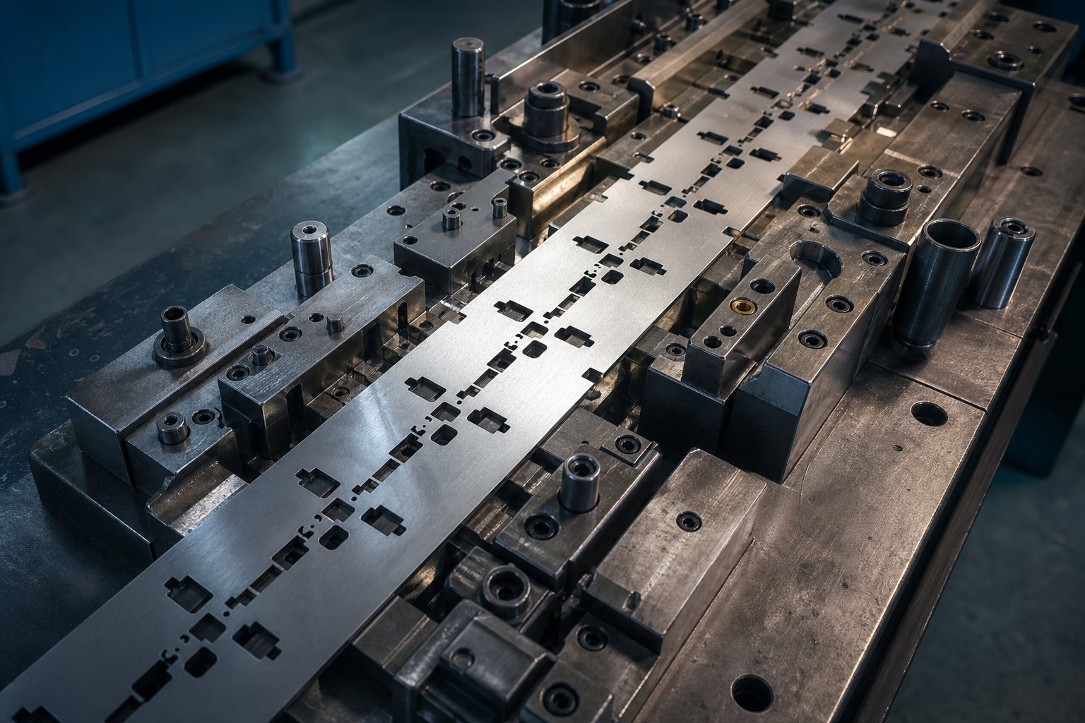
When you strip away the jargon, what is stamping at its core? It is a cold-forming process that cuts and shapes sheet metal using a precision tool called a stamping die. Within progressive die operations, a continuous strip of material advances through multiple stations, and each station performs a cutting or forming operation. The challenge is that every cut and every form displaces material, and that displaced volume has to go somewhere.
This is where bypass notches come in. Unlike incidental trim geometry that simply separates scrap from the workpiece, bypass notches are engineered features with a specific purpose of bypass notches in stamping dies: controlling where and how material moves during strip progression.
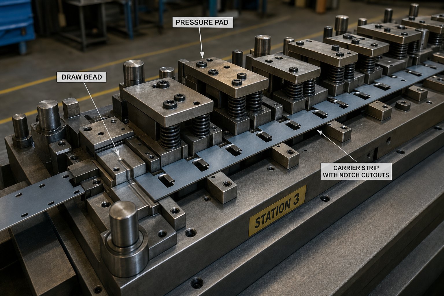
Bypass notches are intentional cutouts in the carrier strip of a progressive stamping die that relieve material stress, accommodate volumetric displacement, and prevent buckling or distortion as the strip advances through forming stations.
That stamping definition matters because it separates bypass notches from every other cut in the strip layout. They are not there to create a part profile or remove scrap. They exist purely to manage material behavior under load.
Why Material Flow Control Matters in Progressive Die Stamping
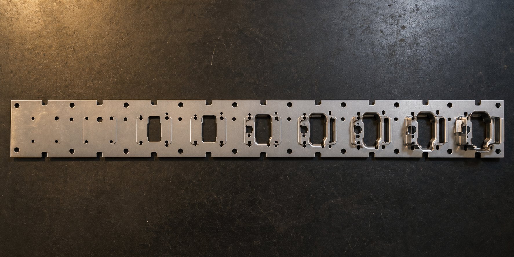
Imagine a strip progressing through eight forming stations at 250 strokes per minute. Each station introduces stress, displaces metal, and work-hardens the surrounding material. Without deliberate flow control, that accumulated stress manifests as strip buckling, carrier distortion, pilot mismatch, and dimensional drift in the finished part.
Understanding what is dies in manufacturing requires recognizing that a die is not just a cutting tool. It is a system where every feature interacts. Bypass notches give material a controlled path to relieve compression and tension so the strip remains flat, feeds consistently, and delivers repeatable dimensions across millions of cycles. For anyone working in what is metal stamping at a professional level, this is foundational knowledge that separates stable production tooling from dies that fail unpredictably.
The real confusion starts when engineers conflate bypass notches with other strip control features that look similar but serve entirely different mechanical functions.
How Bypass Notches Differ from Other Strip Control Features
A progressive die strip contains multiple cutout geometries, and they can all look like simple notches to the untrained eye. The problem is that each one serves a fundamentally different mechanical purpose within the die process. Treating them as interchangeable leads to undersized relief, strip instability, and hours of troubleshooting that trace back to a misidentified feature.
Bypass Notches vs Relief Notches and Trim Cuts
Relief notches prevent material tearing at bend transitions. You'll find them at the intersection of a bend line and a free edge, where their job is to stop crack propagation during forming. Trim cuts, on the other hand, define the outer boundary of the finished part by separating it from surrounding scrap. Both are essential stamping die components, but neither one manages volumetric displacement during strip feed.
Bypass notches do something different entirely. They absorb the compressive forces and material displacement generated as the strip undergoes progressive deformation. Where a relief notch prevents localized fracture and a trim cut creates part geometry, a bypass notch redirects flow to maintain strip flatness and pitch accuracy across all stations.
Lance-and-form features add another layer of confusion. Lancing shears and bends a tab from the strip material without removing a slug. It creates a formed feature within the part itself. Carrier tab cutouts serve the opposite purpose. They define the attachment points that hold the part to the carrier web until final separation. Neither feature addresses the cumulative material stress that bypass notches are designed to relieve.
How Each Strip Control Feature Serves a Different Function
In any die stamp operation, you'll encounter all of these features coexisting in a single strip layout. The risk is designing one when you actually need another. Die stamps used in high-volume progressive applications demand that each cutout geometry is selected for its intended mechanical role, not simply its visual similarity to other features.
The table below breaks down the distinctions that matter for anyone working in die and stamping design. These are the stamping examples where misidentification causes the most downstream problems.
| Feature Name | Primary Function | Placement Logic | Typical Geometry |
|---|---|---|---|
| Bypass Notch | Absorbs volumetric displacement and relieves compressive stress during strip feed | Adjacent to forming stations where material displacement is highest | V-notch, U-notch, or rectangular cutout in carrier edge |
| Relief Notch | Prevents tearing at bend-to-edge intersections | At the junction of bend lines and free edges | Small radius or rectangular slot perpendicular to bend axis |
| Trim Cut | Separates finished part profile from scrap material | Along the final part boundary, typically in later stations | Contoured shear line matching part outline |
| Lance-and-Form | Creates a formed tab or feature without slug removal | Within the part geometry where a raised or bent tab is needed | Single shear line with formed bend at connected edge |
| Carrier Tab Cutout | Defines attachment width holding part to carrier until separation | Between part boundary and carrier strip | Narrow connecting bridge, often with breakaway profile |
The critical distinction is purpose. Bypass notches exist to manage material behavior between stations. Every other feature listed above either creates geometry, prevents fracture, or facilitates part release. Confusing these roles is one of the most common dies and stamping design errors, and it typically only surfaces after the tool is built and the strip starts misbehaving during tryout.
Knowing which feature you need is half the problem. The other half is selecting the right geometry profile for your specific bypass application, which depends on forming severity, material grade, and station operation type.
Bypass Notch Geometry Types and When to Use Each
Three geometry profiles dominate bypass notch design in sheet metal stamping dies: the V-notch, the U-notch, and the rectangular cutout. Each distributes stress differently, accommodates different forming loads, and introduces different trade-offs in carrier strength. Selecting the wrong profile for your application is one of the fastest ways to generate strip problems that look unrelated to notch design.
V-Notch, U-Notch, and Rectangular Geometry Profiles
The V-notch is a wedge-shaped cutout with converging sides meeting at a defined tip radius. It concentrates stress at a narrow point, which makes it effective for controlled, localized relief in tight spaces. Research on U-notch and V-notch geometries confirms that V-notches produce highly localized strain fields at the tip, with deformation confined to a small zone rather than spreading laterally into surrounding material. This focused behavior suits applications where you need precise, directional stress relief without affecting adjacent features.
The U-notch has a semicircular root with parallel or slightly diverging side walls. Its larger tip radius spreads the strain field outward in what researchers describe as a butterfly-wing deformation pattern. That broader distribution reduces peak stress concentration at any single point, making the U-notch more forgiving when stamping sheet metal that is prone to edge cracking under localized loads.
The rectangular notch is the simplest profile: straight walls with a flat bottom. It removes a uniform volume of material and distributes stress relatively evenly across the notch floor. The trade-off is that the sharp corners at the wall-to-floor transition create dual stress concentration points, which can initiate micro-cracks in harder materials if corner radii are not carefully controlled.
Positive vs Negative Bypass Notches in Strip Design
Understanding negative and positive bypass notches in sheet metal forming stamping dies requires thinking in terms of material volume, not just shape. A negative bypass notch removes material from the carrier to create space for displaced metal to flow into. It is the more common approach: you cut away strip material so that forming-induced compression has somewhere to go without buckling the carrier.
A positive bypass notch works in the opposite direction. It retains or extends a local tab of material that guides flow around a formed feature while maintaining carrier support. Think of it as leaving material in place deliberately to steer displacement rather than simply accommodating it. The practical distinction is that positive notches protect carrier strength while managing clearance, and negative notches prioritize volumetric relief at the cost of reduced cross-section.
In practice, most bypass notches sheet metal forming applications use a combination of both types across different stations in a single strip layout. Early stations with mild forming may only need negative cutouts for basic clearance. Later stations where cumulative work hardening and forming severity increase may require positive bypass geometry to maintain strip integrity while still directing flow.
Matching Notch Geometry to Forming Severity
Geometry selection is not a personal preference. It follows the physics of your specific application. The forming severity, strip width, material grade, and station operation type all narrow down which profile will actually work. Among the various types of stamping dies used in production, progressive dies demand the most rigorous geometry matching because the strip must survive every station in sequence.
Selection criteria for each geometry type:
- V-notch: Best for narrow carrier strips, shallow draws, and stations requiring precise directional relief. Choose when available carrier width is limited and you need concentrated stress relief without a wide cutout footprint.
- U-notch: Preferred for moderate to severe forming, thicker stamped sheet metal, and materials with lower elongation. The distributed stress pattern reduces edge-cracking risk where strain levels are high.
- Rectangular: Suited for wide carriers with multiple forming stations, where uniform volume removal matters more than stress distribution. Works well for mild steel and materials with good ductility, but demands generous corner radii in harder grades.
| Geometry Type | Stress Distribution Pattern | Best Use Case | Limitations |
|---|---|---|---|
| V-Notch | Highly concentrated at tip; narrow strain zone confined near notch root | Tight strip layouts, shallow forming, directional relief in limited carrier width | Risk of edge cracking in low-ductility materials; requires precise tip radius control |
| U-Notch | Broadly distributed in butterfly-wing pattern; lower peak stress at root | Moderate to severe forming, AHSS or work-hardened materials, stations with high displacement | Larger footprint reduces available carrier width; less precise directional control |
| Rectangular | Evenly distributed across flat floor; dual concentration at wall-floor corners | Wide carriers, mild to moderate forming in ductile materials, uniform volume removal | Corner stress risers demand generous radii; poor performance in hard or brittle grades |
The geometry you choose also depends on whether you are dealing with negative and positive bypass notches sheet metal stamping dies applications. V-notches and rectangular profiles are most common as negative cutouts for volumetric relief. U-notches work well in both positive and negative roles because their rounded root geometry minimizes crack initiation regardless of whether material is being removed or retained.
Geometry defines the stress pattern, but it does not define the size. The next critical decision is how deep, how wide, and at what radius to cut these notches relative to your material thickness and strip dimensions.
Sizing Bypass Notches for Material Thickness and Strip Width
A correctly shaped notch in the wrong size fails just as badly as the wrong shape entirely. In metal stamping die design, the dimensional parameters of a bypass notch (depth, width, angle, and edge radius) must be calibrated to the specific material thickness, strip width, and station spacing of your progressive tool. Get one ratio wrong, and you are either leaving stress unrelieved or cutting so aggressively that the carrier breaks before it reaches the final station.
Depth and Width Ratios Relative to Material Thickness
Notch depth is the primary variable controlling how much stress relief a bypass notch provides. The general stamping design rule is that notch depth should fall between 1.5x and 3x the material thickness for standard mild steel applications. Go below 1.5x and the cutout is too shallow to meaningfully relieve compressive forces building up during forming. Go above 3x and you begin compromising the carrier's cross-sectional strength, which risks strip breakage or feed instability at high stroke rates.
For steel sheet stamping in higher-strength grades, that ratio tightens. AHSS carriers tolerate less material removal before losing structural integrity, so depths of 1.5x to 2x material thickness are more common. Meanwhile, softer aluminum alloys may need depths approaching 3.5x because the material displaces more readily under forming loads.
Notch width relates directly to the volumetric displacement expected at each forming station. A deep draw that moves significant material volume needs a wider bypass window than a shallow emboss. As a baseline, width should be at least 0.040 inches or the material thickness, whichever is greater. For progressive stations with severe forming, widths of 2x to 4x the material thickness are typical to accommodate the larger displacement volumes.
How Station Spacing Influences Notch Dimensions
Station spacing creates a secondary constraint. Tighter pitch between stations means less carrier length available to absorb stress between forming operations. When station spacing is compact, bypass notches often need to be deeper or wider per station because there is less baseline material between operations to distribute residual forces naturally.
Conversely, generous station spacing (above 16mm) allows cumulative stress to dissipate partially through the carrier itself, which permits more conservative notch sizing. The practical rule in stamping die design is that notch dimensions should scale inversely with available carrier length between stations: less space means more aggressive relief at each point.
Engineers sizing bypass notches for a new strip layout in steel stamping dies can follow this step-by-step logic to establish initial dimensions before simulation or tryout:
- Identify the material thickness and grade. Record yield strength and elongation values from the material certification.
- Determine the forming severity at each station. Classify each operation as mild (shallow emboss, pierce), moderate (partial draw, flange), or severe (deep draw, heavy form).
- Set initial notch depth at 1.5x material thickness for mild stations, 2x for moderate, and 2.5x to 3x for severe forming operations.
- Set initial notch width based on volumetric displacement: 1.5x material thickness for mild, 2.5x for moderate, and 3.5x to 4x for severe stations.
- Check carrier cross-section remaining after notch removal. Ensure that the narrowest point retains at least 60% of the original carrier width to maintain feed stability.
- Adjust dimensions for station spacing. Reduce depth by 10-15% if spacing exceeds 16mm; increase by 10-15% if spacing is below 10mm.
- Specify edge radius at notch boundaries (covered below) and validate with strip simulation or progressive tryout.
Edge Radius Design to Minimize Burr Propagation
Bypass notches burr formation in stamping is a downstream defect source that many engineers overlook during initial metal stamping die design. Every notch cutout produces a sheared edge. Industry data from Xometry's stamping standards indicates that burrs of approximately 10% of material thickness are a normal and expected outcome on cutout features. The problem is that a bypass notch sits in the carrier, which feeds through every subsequent station. Burrs at notch edges drag against lifters, guides, and pressure pads, generating debris that contaminates forming surfaces.
The mitigation is edge radius design. Rather than leaving sharp 90-degree transitions at the notch walls and floor, specify a minimum radius of 0.5x the material thickness at all internal corners. For stamping steel in harder grades, increase that to 0.75x. These radii reduce peak shear stress during the punch stroke, which produces a cleaner cut with less breakaway tearing and smaller burr height.
Equally important is the entry angle at the top of the notch where it opens to the carrier edge. A slight chamfer or radius at this transition prevents the strip from catching on the notch mouth during feed advance. Without it, strip edge deformation accumulates station by station, and what started as a minor burr becomes a misalignment problem that shows up in finished part dimensions.
Sizing gets you in the right range. But where you place these notches within the strip layout (relative to carrier strips, pilot holes, and grain direction) determines whether the sizing actually delivers the stress relief it was designed to provide.
Placement Strategy in Progressive Die Strip Layouts
A perfectly sized bypass notch in the wrong location does nothing useful. In sheet metal stamping, placement is where theory meets strip reality. The notch must interact with the actual stress field generated by the forming station it serves, not just sit at a convenient open spot in the carrier. Placement decisions involve three interdependent variables: proximity to forming stations, spatial relationship to pilot holes, and alignment with the material grain direction.
Positioning Notches Relative to Carrier Strips and Pilot Holes
Bypass notches belong in the carrier strip, the material web that connects your stamping parts as they advance through each station. Their position along that carrier must balance two competing needs. First, they need to be close enough to the forming station that they actually intercept the displacement and compressive stress generated during the operation. Second, they cannot encroach on pilot holes or interfere with the strip's registration system.
Pilot holes are the positioning reference for the entire strip. As MetalForming Magazine notes, pilots must enter the strip before other punches engage, and their locating accuracy depends on consistent hole geometry. A bypass notch placed too close to a pilot hole deforms the surrounding material, elongating the hole and degrading positional accuracy station after station. The practical rule in metal stamping tooling is to maintain a minimum of 2x material thickness clearance between any notch boundary and the nearest pilot hole edge.
Laterally, notches should sit on the side of the carrier closest to the forming operation generating the highest displacement. If a draw station pulls material toward the part center, the bypass notch on that side of the carrier absorbs the resulting tension in the web. Placing it on the opposite side forces stress to travel across the full carrier width before finding relief, which invites buckling in between.
Adjusting Bypass Strategy Across Multiple Stations
A strip entering the first station of a die stamping press is in its softest, most ductile condition. By the time it reaches station six or eight, cumulative work hardening has raised the yield strength locally by 20-40%, depending on material grade and forming severity. That hardened material resists displacement more aggressively, meaning the same notch depth that provided adequate relief at station two may be insufficient at station seven.
This is where stamping tooling design must think progressively, not just in terms of individual stations. Early stations with mild punching stamping operations (piercing, light embossing) typically need only shallow bypass relief or can sometimes share a single notch between adjacent stations. Downstream stations performing deep draws or heavy flanging require dedicated notches with greater depth and width, reflecting the elevated stress state of the work-hardened strip.
Stage tooling logic applies here: each forming stage imposes cumulative strain that carries forward. The strip does not reset between operations. Finite element research on progressive die sequence design confirms that thickness distributions and strain hardening must be predicted for each stage and carried over to the successive stage. Bypass notch placement follows the same principle. What you need at station eight depends directly on what happened at stations one through seven.
Grain Orientation and Anisotropy Considerations
Rolled sheet metal is not isotropic. The grain structure aligns preferentially in the rolling direction, creating measurable differences in yield strength, elongation, and flow behavior between the longitudinal, transverse, and 45-degree orientations. In transfer stamping and progressive operations alike, this anisotropy directly affects how material responds to bypass notch relief.
When the strip feeds parallel to the rolling direction (the most common orientation), material flows more readily along the grain than across it. Bypass notches oriented perpendicular to feed direction exploit this by allowing displacement to move along the path of least resistance. Conversely, if your strip layout runs transverse to the grain, you'll notice higher resistance to flow at notch boundaries, which may require deeper cutouts or U-notch profiles to achieve equivalent relief.
Bypass notch placement is a system-level decision tied to the entire strip layout, not an isolated feature. Each notch position must account for upstream forming history, downstream stress accumulation, pilot registration requirements, and material anisotropy simultaneously.
Ignoring grain effects is especially costly in higher-strength materials where the difference in r-value (plastic strain ratio) between rolling and transverse directions can exceed 30%. That directional bias means the same notch geometry produces different flow behavior depending on strip orientation, and placement decisions must compensate accordingly.
Placement and sizing together define the geometric envelope of your bypass strategy. But the material itself determines whether those geometric decisions actually produce the flow behavior you intended. Yield strength, ductility, and work hardening rate each impose their own constraints on what any given notch can accomplish.
Material Properties That Drive Bypass Notch Design Decisions
Geometry and placement set the structural framework for bypass relief, but the material flowing through your die determines whether those decisions actually work. Two strips with identical dimensions and notch layouts will behave completely differently if one is mild steel at 210 MPa yield strength and the other is DP780 at 500 MPa. The material's resistance to deformation, its capacity to stretch before cracking, and how quickly it hardens under strain all dictate what a bypass notch can realistically accomplish at each station.
How Yield Strength and Ductility Affect Notch Sizing
Yield strength is the stress level at which a material begins to deform plastically. In bypass notch design, it defines the force threshold the strip must overcome before material actually displaces into the relief zone. A higher yield strength of steel means greater resistance at notch boundaries, which translates to less material flow for the same notch geometry. The practical consequence is that higher-strength grades need deeper or wider notches to achieve equivalent stress relief.
Understanding yield strength vs tensile strength matters here because bypass notches operate in the plastic regime between these two values. Tensile strength caps the maximum stress the strip can carry before fracture, while yield strength marks where permanent deformation begins. The gap between them, quantified by elongation, represents the material's working range for controlled flow. As Ulbrich's formability research notes, high elongation values indicate good ductility, making materials suitable for complex shapes and deep drawing operations. In bypass terms, higher elongation means the carrier can tolerate more aggressive notch geometries without edge cracking.
The modulus of elasticity of steel (approximately 210 GPa for all grades) governs elastic recovery after each press stroke. While this value stays constant across steel grades, it drops to roughly 70 GPa for aluminum alloys. That threefold difference means aluminum strips spring back three times more than steel at equivalent stress levels, as documented by AHSS Insights springback data. For bypass notch design, greater elastic recovery means the material partially closes back after displacement, reducing the effective relief provided by a given notch depth. Aluminum applications therefore demand proportionally larger notch volumes to compensate for this elastic snap-back.
Work Hardening Rate and Its Impact on Bypass Requirements
Work hardening is the mechanism by which metal strengthens as it deforms. Every forming station increases the local flow stress in the carrier strip, and that elevated strength carries forward to the next station. The rate at which this happens, quantified by the strain-hardening exponent (n-value), directly determines how quickly your bypass notches become inadequate as the strip progresses through the die.
The relationship between strain hardening and work hardening is cumulative in progressive operations. A material with a high n-value (like DP steels at 0.15-0.20 in lower strain ranges) strengthens rapidly during early deformation. Research from MetalForming Magazine confirms that advanced high-strength steels such as dual-phase grades have high n-value at lower strain ranges, then level off to values approximating those of HSLA steels at the same incoming yield strength. This front-loaded hardening means that DP strips reach elevated flow stresses faster, demanding earlier bypass intervention in the strip layout.
Materials with a high work hardening exponent accumulate residual stress at an accelerated pace. By station four or five, the carrier material adjacent to forming zones may have work-hardened 30-50% above its incoming yield strength. A bypass notch sized for the as-received material properties now faces significantly stiffer metal that resists displacement more aggressively. The engineering response is progressive escalation: notch depth and width must increase station by station to match the rising flow stress of the work-hardened strip.
Adapting Notch Design for AHSS, Aluminum, and Mild Steel
Each material category presents a distinct combination of challenges. Mild steel offers high ductility and moderate yield strength, making it the most forgiving substrate for bypass design. AHSS grades flip that equation with high strength but reduced elongation and more aggressive springback. Aluminum introduces a completely different elastic modulus that changes the fundamental displacement mechanics at notch boundaries.
The stress-strain curve shape tells you whether material will flow predictably or fight the notch geometry. Mild steel produces a smooth, gradually rising curve with a clear yield plateau, meaning displacement at notch boundaries is predictable and steady. AHSS grades exhibit a steep initial rise with continuous yielding (no plateau), creating a narrow working window where the material transitions rapidly from elastic to heavily work-hardened. Aluminum curves fall between these extremes in shape but the lower elastic modulus means significantly more elastic strain recovery at every point.
| Material Category | Typical Yield Strength Range | Elongation Behavior | Work Hardening Tendency | Bypass Notch Implications |
|---|---|---|---|---|
| Mild Steel (CR, DR grades) | 140-280 MPa | 26-42% total elongation; high uniform elongation with clear yield plateau | Moderate n-value (0.18-0.22); gradual, predictable strengthening across strain range | Standard notch ratios (1.5-3x thickness) work reliably; U-notch or rectangular profiles tolerated; forgiving of minor sizing errors |
| AHSS (DP, TRIP, CP grades) | 350-1000+ MPa | 10-25% total elongation; limited uniform elongation with continuous yielding | High n-value at low strains (0.15-0.20), declining at higher strains; rapid early strengthening | Reduced notch depth range (1.5-2x thickness) to preserve carrier integrity; U-notch preferred to minimize stress concentration; earlier bypass intervention needed due to rapid hardening |
| Aluminum (5xxx, 6xxx series) | 90-350 MPa | 12-30% total elongation; varies widely by alloy and temper condition | Lower n-value (0.10-0.25 depending on alloy); moderate strengthening but high elastic recovery | Deeper notches needed (2.5-3.5x thickness) to compensate for elastic snap-back; generous edge radii critical due to lower fracture toughness; wider notches for volumetric compensation of springback |
For AHSS applications specifically, the combination of high flow stress and limited ductility creates a narrower safe design window. As AHSS springback research documents, the magnitude of springback is a function of the as-formed flow stress, which combines starting yield strength with the work hardening occurring during forming. Both values are higher in AHSS compared with mild steels. This elevated springback directly impacts bypass effectiveness because the elastic recovery partially negates the displacement relief that the notch provides. The carrier material adjacent to the notch springs back toward its pre-formed position, reducing effective clearance.
The practical takeaway: you cannot design bypass notches from geometry alone. Material properties impose hard constraints on what any given notch size and shape can deliver. A notch strategy validated in mild steel will underperform in AHSS and behave differently again in aluminum. Each material category demands its own sizing envelope, geometry selection, and station-by-station escalation logic.
When these material-driven constraints are violated, the resulting defects follow predictable patterns. Edge cracking, carrier breakage, strip misalignment, and wrinkling each trace back to specific mismatches between notch design and material behavior.
Troubleshooting Defects Caused by Improper Bypass Notch Design
Those predictable failure patterns are exactly what makes diagnosis possible. Each defect type leaves a signature in the strip that points back to a specific mismatch between notch geometry, sizing, or placement and the actual material behavior under load. The challenge is distinguishing bypass-related defects from issues caused by other die parameters, because the symptoms often overlap.
Edge Cracking and Stress Concentration at Notch Boundaries
Edge cracking at notch boundaries is the most common failure mode in work-hardened carrier strips. The mechanism is straightforward: every bypass notch creates a geometric discontinuity, and geometric discontinuities concentrate stress. When the localized stress at the notch root exceeds the material's fracture threshold, micro-cracks initiate and propagate outward with each press stroke.
The s-s curve (stress-strain curve) tells you exactly where this threshold sits. After multiple forming stations, deformation hardening raises the local flow stress while simultaneously reducing the remaining elongation capacity. A notch root that was well within safe limits at station two may be operating at the fracture boundary by station six because strain hardening has consumed most of the material's ductility reserve.
- Insufficient edge radius: Sharp internal corners at the notch root create stress multiplication factors of 3x to 5x. The material cracks at the concentration point even when bulk stress levels remain moderate.
- Excessive notch depth: Reducing the carrier cross-section below 40% of original width raises nominal stress in the remaining material above the yield stress, accelerating crack initiation at any geometric defect.
- Burr-initiated cracking: Rough shear edges from worn punch tooling act as pre-existing flaws. Under cyclic loading, these burrs become crack initiation sites that propagate into the carrier with each stroke.
Corrective actions include increasing the notch root radius to at least 0.75x material thickness, reducing notch depth to restore carrier cross-section, and maintaining punch sharpness to minimize burr height at cutout edges.
Strip Misalignment and Carrier Breakage Scenarios
Strip misalignment from asymmetric bypass design is subtler but equally damaging. When notches on one side of the carrier provide more relief than the other, material flows preferentially toward the relieved side. The strip develops camber, drifting laterally as it advances. MetalForming Magazine's strip analysis confirms that when only one carrier web stretches or distorts, the resulting camber causes the strip to veer to one side, binding in guide rails and producing short feeds.
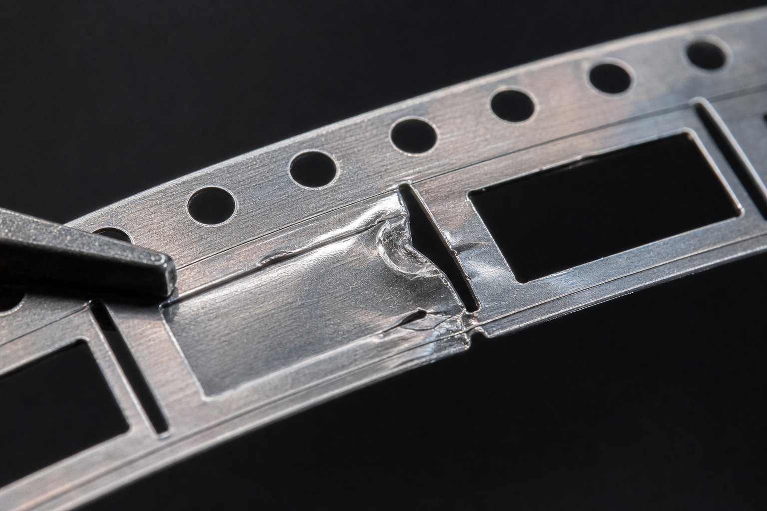
Carrier breakage represents the extreme case. It happens when bypass notches remove so much cross-section that the remaining carrier cannot withstand the tensile forces generated during feed advance. The yielding point of steel in the thinned carrier section drops below the feed tension, and the strip fractures mid-progression. High-speed operations above 200 strokes per minute amplify this risk because dynamic feed forces add impulse loading on top of the static stress state.
Wrinkling and buckling between stations stem from the opposite problem: insufficient bypass relief. When compressive stress from forming operations has nowhere to go, the carrier buckles out of plane. This distortion lifts the strip off lifters, misaligns it relative to pilots, and introduces dimensional errors in every downstream station. The root cause is that the notch volume is too small to accommodate the actual volumetric displacement generated by the forming operation.
Diagnostic Logic for Bypass-Related Defects
The difficulty in troubleshooting is that bypass notch defects mimic symptoms caused by other parameters. Strip misalignment also results from feed-roll pressure issues or coil camber. Cracking can originate from material defects or excessive forming severity. Engineers need a structured sequence to isolate the root cause.
When a strip-related defect appears, follow this diagnostic sequence to determine whether the bypass notch design is the source:
- Inspect the defect location relative to bypass notches. If cracking, buckling, or misalignment occurs within two material thicknesses of a notch boundary, the notch is the primary suspect.
- Check whether the defect is station-specific or progressive. A defect that worsens station by station indicates cumulative stress buildup from inadequate relief, pointing to undersized notches. A defect isolated to one station suggests a local geometry or clearance problem.
- Examine both carrier edges for symmetry. If one side shows distortion, elongation, or cracking while the other remains intact, asymmetric bypass placement is the likely cause.
- Measure the remaining carrier cross-section at the narrowest point. If it falls below 50% of the original width, carrier integrity is compromised regardless of other factors.
- Compare the yield strength yield stress of the incoming material to the certified values used during die design. Material running at the high end of the specification tolerance will resist bypass flow more aggressively than the nominal design assumed.
- Rule out non-notch causes: verify feed-roll pressure, pilot condition, coil camber, and lubrication before modifying notch geometry. If these parameters are within specification and the defect correlates spatially with notch locations, proceed with notch modification.
If the diagnostic points to bypass design, the corrective path depends on defect type. Edge cracking calls for larger root radii and reduced depth. Misalignment requires rebalancing notch relief symmetrically across both carriers. Buckling demands increased notch volume (depth or width) to accommodate unrelieved compression. Carrier breakage requires either reducing notch depth or widening the carrier in the strip layout.
These defect scenarios treat bypass notches as standalone features. In production tooling, they rarely work alone. Draw beads, pressure pads, and binder forces all interact with notch geometry to control the total material flow system, and understanding that interaction determines whether your corrective action actually solves the problem or simply shifts it downstream.
Integrating Bypass Notches with Other Die Flow Control Features
No bypass notch operates in isolation inside a production stamping tool and die set. It shares flow control responsibility with draw beads, pressure pads, blank holders, and binder force systems that each exert their own influence on how material moves through the die. The interaction between these features determines whether your strip behaves predictably or whether fixing one problem with notch geometry creates a new one somewhere else in the system.
Bypass Notches Working with Draw Beads and Pressure Pads
Draw beads generate restraining force by forcing material to bend and unbend around a raised geometry before it enters the die cavity. As bead geometry research confirms, a combination of work hardening from the sheet metal bending around the bead radii, as well as sliding friction, produces a restraining force that controls metal flow from the blank edge. That restraining effect directly reduces the volume of material that bypasses notches must accommodate. When draw beads successfully limit inward flow, less displaced material reaches the carrier strip, which means notch depth and width can be reduced without compromising strip stability.
The reverse is equally true. When draw bead radii wear down or binder surfaces degrade, restraining force drops and more material flows freely into forming zones. The excess displacement that beads once contained now lands on your bypass notches, which may not be sized to handle it. This is why experienced tool and die maker professionals check bead condition as part of any bypass-related troubleshooting. A notch defect that appeared suddenly after months of stable production often traces back to bead wear rather than a flaw in the original notch design.
Pressure pads add another layer. They hold material flat against the die surface during forming, preventing localized lifting or wrinkling between the blank holder and the punch. In progressive dies producing metal stamping components, spring-loaded pressure pads control strip behavior in the immediate vicinity of each forming station. Sufficient pad pressure keeps material seated, which reduces the lateral compressive forces that bypass notches must relieve. Insufficient pressure allows the strip to lift and buckle locally, pushing more flow responsibility onto the notch geometry.
Blank holder force (BHF) governs overall material restraint at the periphery of draw operations. Research from The Fabricator documents that excessive material flow and low blank holder force may cause wrinkling, while insufficient flow causes tearing or fracture. In precision die stamping operations, BHF and bypass notches serve complementary roles: the blank holder restrains material globally, while notches provide localized volumetric relief at specific stations. When BHF increases, less material displaces into the carrier, reducing notch demands. When BHF decreases (intentionally or through cushion degradation), the strip absorbs more unrestrained flow, and notches must compensate.
Decision Framework for Combining Material Flow Controls
The engineering question is not whether to use bypass notches or other flow controls. It is how much responsibility each feature carries for a given part complexity. Simple geometries with shallow forms and ductile materials may need only bypass notches and basic blank holder pressure. Complex automotive stamping dies with deep draws, sharp radii, and AHSS grades demand the full combination working in concert.
Use this decision logic to determine the right combination for your application:
- If forming severity is mild and material elongation exceeds 30%: Bypass notches alone typically provide sufficient flow control. Draw beads are unnecessary, and standard spring pressure pads maintain strip flatness.
- If forming involves moderate draws with more than 15% thinning: Combine bypass notches with draw beads to split flow control between the strip carrier and the blank periphery. Size notches 20-30% smaller than standalone requirements because beads carry part of the restraining load.
- If the part requires deep draws with high-strength material: Deploy the full system. Draw beads restrain peripheral flow, variable BHF controls draw-in rate through the stroke, pressure pads maintain local flatness, and bypass notches handle residual displacement that other features cannot absorb. Notch sizing here follows the residual volume after other controls are accounted for, not the total displacement volume.
- If asymmetric part geometry creates unbalanced flow: Use draw beads selectively on the high-flow side while placing bypass notches opposite to equalize carrier stress. This combination prevents the strip camber that results from one-sided relief alone.
The key principle for any stamping tool and die application is that each flow control feature has an effective range. Draw beads excel at peripheral restraint but cannot address stress buildup deep within the carrier. Blank holders control global force but lack station-specific precision. Bypass notches deliver localized, station-specific relief but cannot restrain bulk material flow across the flange. The system works when each feature operates within its strength rather than compensating for another feature's failure.
For metal tool and die applications involving complex geometries, multi-material stacks, or tight tolerance industrial metal stamping, the interaction between these features becomes difficult to predict through manual calculation alone. FEA simulation helps, but production validation remains essential. Engineers working through these multi-feature flow control challenges, where bypass notch design intersects with overall die architecture decisions, often benefit from partnering with specialists who build custom progressive tooling. YICHEN's stamping die solutions connect tooling engineers to die design expertise covering the full range of flow control integration, from notch geometry and draw bead interaction to binder system optimization across the complete die structure.
Getting these interaction effects right during design prevents the iterative tryout loops that consume weeks of press time. The final step is consolidating all of these principles into a repeatable engineering workflow that moves from strip layout through production validation.
Engineering Principles for Effective Bypass Notch Implementation
Every decision covered in this article, from geometry selection to material-driven sizing to multi-feature interaction, collapses into a single engineering reality: bypass notch design is not a standalone task. It is inseparable from strip layout planning, material selection, and the broader flow control architecture of your die. Treating it as an afterthought or a copy-paste detail from a previous tool is where most stamping process failures originate.
Consolidated Decision Logic for Bypass Notch Engineering
The metal stamping process demands that each bypass decision follows logically from the one before it. You cannot size a notch without knowing the material. You cannot place it without understanding the strip layout. And you cannot validate it without measuring outcomes in production. This sequential logic applies whether you are designing tooling for stamped steel automotive brackets or precision stamped metal parts for electronics assemblies.
Follow this checklist in order when engineering bypass notches for any new progressive die application:
- Define the strip layout first. Establish carrier type, strip width, station count, station spacing, and pitch before any notch decisions are made.
- Characterize the material. Record yield strength, elongation, n-value, and elastic modulus from certified data. Identify whether the grade is mild steel, AHSS, or aluminum, and select the corresponding sizing envelope.
- Map forming severity station by station. Classify each operation and note where volumetric displacement peaks. These are your primary bypass locations.
- Select notch geometry based on material ductility and carrier width. V-notch for tight layouts and directional relief, U-notch for moderate-to-severe forming or limited-ductility grades, rectangular for wide carriers with ductile materials.
- Size depth and width using material thickness ratios. Start at 1.5x thickness for mild stations, scale up to 3x for severe operations, and adjust for station spacing constraints.
- Place notches relative to forming stations, pilot holes, and grain direction. Maintain minimum 2x material thickness clearance from pilots. Position on the carrier side closest to peak displacement.
- Account for interaction with draw beads, pressure pads, and blank holder force. Reduce notch sizing proportionally when other flow controls carry part of the restraining load.
- Specify edge radii at all notch boundaries (minimum 0.5x material thickness) to minimize burr propagation and crack initiation.
- Validate in progressive tryout. Run at production speed and inspect for edge cracking, strip camber, carrier thinning, and dimensional drift in finished parts.
- Iterate based on measurable data, not assumptions. Adjust notch parameters only after confirming that defects correlate spatially and temporally with notch locations.
Measuring Bypass Notch Effectiveness in Production
A well-designed bypass strategy proves itself through three measurable outcomes in the metal stamping manufacturing process. Strip feed reliability is the first: consistent pitch accuracy across all stations without short feeds, misfires, or camber-induced binding. If your feeder alarm rate drops below 0.1% per shift, the bypass system is controlling stress accumulation effectively.
Dimensional consistency in the finished metal stamped part is the second metric. When bypass notches properly relieve forming stress, the carrier maintains registration with pilot holes, which preserves feature-to-feature dimensions across millions of strokes. Statistical process control data (Cpk values above 1.33 on critical dimensions) confirms that flow control is stable.
Scrap rate reduction is the third validation point. Carrier breakage, edge cracking, and buckling-induced misalignment all generate scrap. A metal parts stamping operation with optimized bypass design should see carrier-related scrap below 0.5% of total production volume. If scrap trends upward over time, worn draw beads or degraded pressure pad springs are often the cause rather than the original notch design.
These metrics close the loop between design intent and production reality. Engineers ready to move from theory to production tooling, where bypass notches, clearance, burr control, and material flow must be optimized together as a complete system, can connect with YICHEN's custom stamping die solutions for design support that bridges the gap between strip layout planning and validated, production-ready die architecture.
Frequently Asked Questions About Bypass Notches in Stamping Dies
1. What is the purpose of bypass notches in progressive stamping dies?
Bypass notches serve as intentional cutouts in the carrier strip that relieve compressive stress, accommodate volumetric displacement from forming operations, and prevent strip buckling or distortion during feed advancement. Unlike relief notches that prevent tearing at bend transitions or trim cuts that define part profiles, bypass notches specifically manage material behavior between stations to maintain strip flatness, consistent pitch accuracy, and dimensional stability across millions of press cycles.
2. How do you determine the correct depth for a bypass notch?
Bypass notch depth is sized as a ratio of material thickness, typically ranging from 1.5x to 3x depending on forming severity and material grade. Mild forming stations start at 1.5x thickness, moderate operations use 2x, and severe draws require 2.5x to 3x. For AHSS grades, the range tightens to 1.5x-2x because higher strength reduces tolerance for cross-section loss. Aluminum may need depths up to 3.5x to compensate for elastic snap-back. The remaining carrier cross-section should retain at least 60% of original width after notch removal to ensure feed stability.
3. What is the difference between positive and negative bypass notches?
Negative bypass notches remove material from the carrier strip to create open space where displaced metal can flow during forming operations. They are the more common type and prioritize volumetric relief. Positive bypass notches retain or extend a local tab of material that guides flow around formed features while preserving carrier support. They protect structural integrity while steering displacement. Most progressive die strip layouts use a combination of both, with negative notches handling early mild stations and positive geometry maintaining carrier strength at later, more severe forming stations.
4. Why do bypass notches cause edge cracking in stamping operations?
Edge cracking at bypass notch boundaries results from stress concentration at geometric discontinuities exceeding the material's fracture threshold. Three primary causes drive this failure: insufficient edge radius at the notch root creating stress multiplication of 3x-5x, excessive notch depth reducing carrier cross-section below safe limits, and burr-initiated cracking from worn punch tooling. Work hardening across multiple stations compounds the problem by raising local flow stress while consuming ductility reserve. Corrective actions include increasing root radius to 0.75x material thickness minimum, reducing depth, and maintaining punch sharpness.
5. How do bypass notches interact with draw beads and blank holder force?
Bypass notches share flow control responsibility with draw beads, pressure pads, and blank holder force in a complementary system. Draw beads restrain peripheral material flow through bending and friction, reducing the displacement volume that notches must handle. When beads carry part of the restraining load, notch sizing can be reduced by 20-30%. Blank holder force controls global material restraint while notches provide localized station-specific relief. Engineers working with complex multi-feature flow systems can partner with specialists like YICHEN (https://www.yichen-group.com/stamping-die/) for custom die design support that optimizes the interaction between all flow control features.


