


What Bypass Notches Do in Progressive Stamping Dies
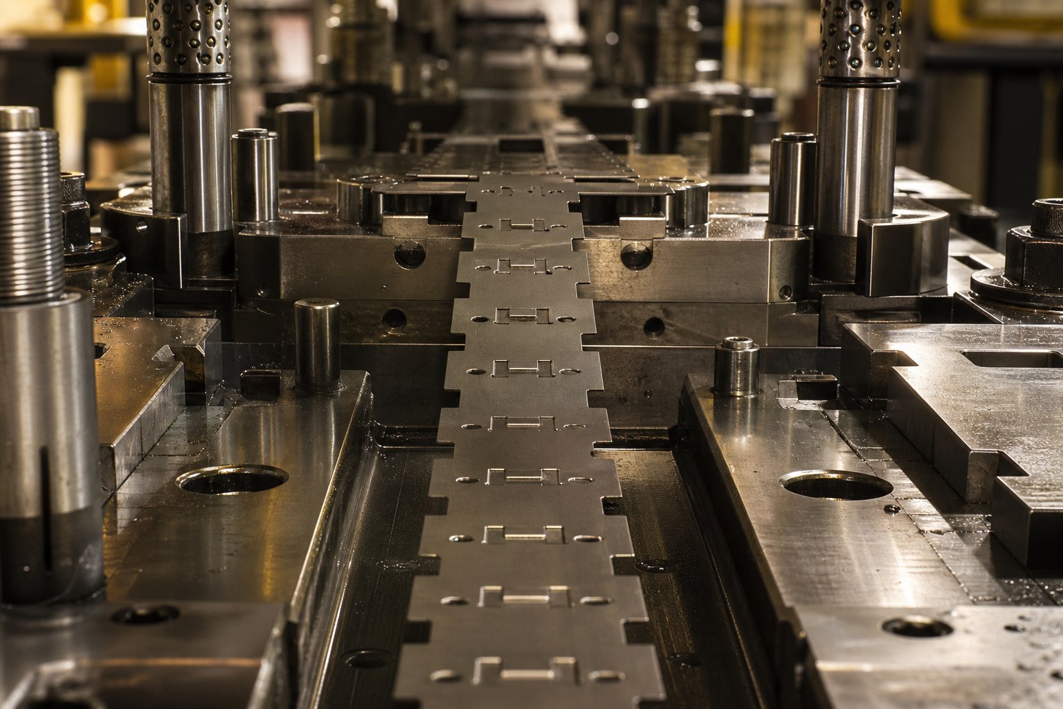
When you run a progressive stamping die, the strip of sheet metal indexes forward one precise progression length with every press cycle. But here is the problem: stationary die components like lifters, forming steels, and pilots physically occupy space within the die. Previously formed features on the strip can collide with those components during indexing if nothing accounts for the clearance gap.
That is exactly the problem bypass notches solve.
What Are Bypass Notches in Progressive Stamping Dies
A bypass notch is an intentional material removal or deformation in the carrier strip that allows the strip to advance past stationary die components without interference during indexing.
Think of it as a relief feature built directly into the strip. Each time the carrier web moves forward, the bypass notch provides clearance so the strip passes lifters, pilot pins, and forming steels cleanly. Without these notches, you would see misfeeds, strip buckling, or outright die damage within the first few press cycles. The bypass notch function in stamping dies is fundamentally about preserving smooth, uninterrupted strip advancement in progressive stamping.
Why Bypass Notches Are Critical to Strip Progression
In a progressive die, the carrier web ties each part together and moves the entire strip from station to station. The distance between station centerlines must remain constant throughout the press stroke. Any interference between the strip edge and a die component disrupts that relationship, distorts pilot holes, and cascades registration errors downstream.
Bypass notches prevent that interference by creating localized clearance zones along the carrier. They fall into two fundamental categories: negative bypass notches, which remove material from the strip, and positive bypass notches, which deform material out of the strip plane without cutting it away. Each type produces a different strip profile, generates different effects on carrier strength, and suits different design scenarios. Understanding how they differ is the starting point for any sound bypass notch design decision.
Negative vs Positive Bypass Notch Geometry Compared
The difference between negative and positive bypass notches comes down to one core question: does the notch remove material, or does it move material? That distinction drives everything from how you cut the tooling to how the strip behaves across dozens of stations. Here is a direct look at each type.
Negative Bypass Notch Geometry and Formation Method
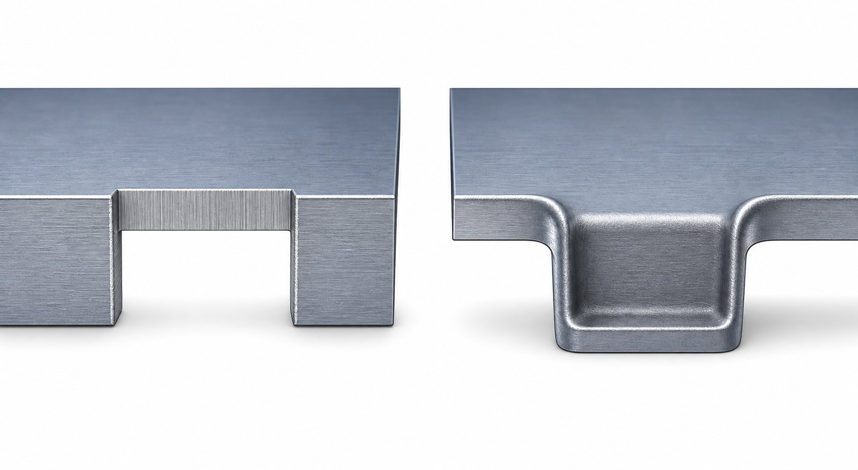
A negative bypass notch removes material from the carrier strip edge, creating a relieved pocket or cutout. Imagine a small rectangular or semicircular bite taken out of the strip edge. The carrier physically has less material at that location, and the resulting void provides clearance for die components as the strip indexes forward.
The bypass notch formation method for a negative notch mirrors a standard trim or notching operation. A dedicated punch descends into a mating die cavity, shearing the material cleanly away. The cut slug drops through the die as scrap. What remains is a strip with an open notch profile along its edge, sized to clear whatever die component sits in the path of travel.
The resulting strip profile shows a distinct gap at each notch location. You will notice that the carrier cross-section is reduced at those points, which has structural implications for downstream stations.
Positive Bypass Notch Geometry and Formation Method
A positive bypass notch takes a fundamentally different approach. Instead of cutting material away, it deforms material outward from the strip plane, typically pushing a small tab downward. The strip retains its full edge profile, but a coined or embossed section displaces below the travel plane, creating clearance above.
The positive bypass notch coining method uses a punch that presses a localized area of the strip into a shallow cavity in the die block. This action is similar to a standard coining or embossing operation: high localized pressure plastically deforms the material without separating it. No slug is produced, and no material leaves the strip.
The resulting strip profile remains continuous along the edge. The notch is only visible as a depressed zone when viewed from the side. Clearance depends entirely on how far the material displaces below the strip travel plane.
Side-by-Side Comparison
The table below contrasts both types across the parameters that matter most during die design. This comparison addresses the negative bypass notch geometry in a progressive die versus its positive counterpart across every critical variable.
| Parameter | Negative Bypass Notch | Positive Bypass Notch |
|---|---|---|
| Geometry type | Open cutout or pocket at strip edge | Coined or embossed tab below strip plane |
| Formation method | Punch-and-die cutting (shear action) | Coining or embossing (plastic deformation) |
| Material removal | Yes, slug is generated | No, material remains attached |
| Strip edge profile | Discontinuous, open gap at notch | Continuous, no visible edge interruption |
| Typical clearance achieved | Equal to full notch depth (unrestricted) | Limited by coin depth and material springback |
| Scrap generation | Yes, one slug per notch per cycle | None |
Each type carries trade-offs that reach beyond geometry alone. Strip width constraints, material properties, and the number of stations requiring clearance all influence which approach delivers the most reliable strip progression without compromising carrier integrity.
When to Choose Positive Over Negative Bypass Notches
Knowing the geometric difference between these two notch types is useful, but the real engineering challenge lands during the design review. Which type do you actually spec for a given die? The answer depends on a handful of interacting variables, from the physical dimensions of your carrier strip to how many stations will demand clearance. Here is a bypass notch design decision framework that connects those variables to a clear selection path.
Part Geometry and Strip Width Considerations
The carrier strip width choice is often the first filter in the decision. A narrow carrier strip with minimal edge stock cannot afford to lose material. Every negative bypass notch removes a section of that edge, reducing the carrier cross-section at that point. If your strip layout already pushes the carrier width to its lower limit, those cutouts can thin the strip to a point where it buckles or tears during feeding.
Positive bypass notches preserve the full edge profile. The material stays attached, it just displaces below the travel plane. For tight strip layouts where edge stock measures only a few material thicknesses wide, this approach keeps the carrier intact while still providing component clearance.
Wider strips with generous edge stock tell a different story. When you have 8 mm or more of edge material beyond the part boundary, removing small notch sections barely affects structural performance. Negative notches become practical because the remaining carrier cross-section still supports smooth feeding across all stations.
Part geometry complexity matters here too. Imagine a part with deep draws, multiple bends, and lanced features. That part demands a stretch web carrier that can flex both vertically and horizontally during forming. Adding negative bypass notches near those flex zones weakens the attachment web at the worst possible location. A positive notch, by contrast, adds a localized deformation without severing load-bearing material.
Material Thickness and Type as Selection Factors
Material properties directly influence whether a positive notch can even form properly. The coining action that creates a positive bypass notch requires the material to deform plastically into a shallow cavity without cracking. That means ductility matters.
Thinner, more ductile materials like low-carbon steel under 1.0 mm, soft aluminum alloys, or brass respond well to the coining deformation. The material flows cleanly into the die pocket, holds its displaced shape, and provides consistent clearance cycle after cycle.
Thicker or harder materials resist that coining action. High-strength low-alloy steels above 1.5 mm, stainless steel in tempered conditions, or spring steels may crack at the coin radius or spring back so aggressively that the notch provides insufficient clearance after forming. In those cases, a negative bypass notch is the safer choice. The punch-and-die shearing action works regardless of material ductility since it simply cuts the material away rather than asking it to flow.
Material thickness also affects the achievable coin depth in positive notches. A 0.5 mm strip coined downward by 1.5 mm produces a clean displacement. A 2.0 mm strip needing the same 1.5 mm clearance requires coining the material less than one full thickness, which limits the practical depth and risks incomplete deformation. Negative notches face no such constraint since the cut depth is governed only by punch geometry.
Progression Requirements and Station Count
The number of die stations requiring bypass clearance introduces a cumulative effect. Each negative notch removes material. Ten stations each requiring a bypass notch means ten locations where the carrier has been thinned. The cumulative weakening can compromise strip rigidity at the feed line, which carrier strength principles identify as critical to smooth progression.
Positive notches avoid this cumulative material loss. Even across a 15-station die, the carrier retains its full edge cross-section at every point. The trade-off is that each coined zone introduces a localized stress concentration, but the structural reduction is far less severe than an open gap.
For high-station-count dies where strip integrity must survive long progression lengths, positive notches often win on carrier strength alone. For shorter dies with three or four stations, negative notches usually present no cumulative risk.
Use the checklist below during your design review to guide the selection:
- Carrier strip edge stock is less than 4x material thickness: favor positive notches
- Material thickness exceeds 1.5 mm or material hardness exceeds 40 HRC: favor negative notches
- Material is ductile with elongation above 20%: positive notches form reliably
- Die has more than 8 stations requiring bypass clearance: favor positive notches for cumulative strength preservation
- Required bypass clearance exceeds 2x material thickness: favor negative notches for guaranteed depth
- Strip layout uses stretch web carriers near notch zones: favor positive notches to avoid weakening flex attachments
- Scrap management is constrained or slug disposal is difficult: favor positive notches (no slug generated)
- Springback compensation is difficult to maintain over long runs: favor negative notches for consistent clearance
These criteria interact. A thin, ductile material in a 12-station die with narrow carriers practically demands positive notches. A thick stainless steel blank in a 4-station die with wide edge stock points clearly toward negative notches. Most real-world applications fall somewhere between these extremes, requiring the designer to weigh trade-offs and sometimes mix both types within a single strip layout.
Selecting the right bypass notch type locks in the design direction. The next challenge is sizing that notch correctly, because an undersized notch causes interference and an oversized notch sacrifices strip strength with no added benefit.
How Bypass Notch Dimensions Are Determined
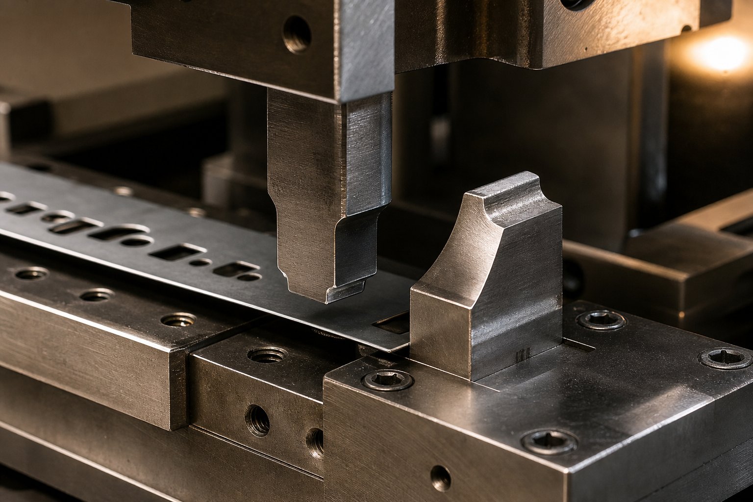
Choosing between a positive and negative bypass notch sets the design direction. Sizing that notch correctly determines whether it actually works in production. An undersized notch catches on die components and causes misfeeds. An oversized notch wastes carrier material or introduces unnecessary stress concentrations. The sweet spot lies in understanding what drives those dimensions from an engineering standpoint.
Calculating Notch Depth and Width for Adequate Clearance
The fundamental purpose of any bypass notch is clearance. The strip must pass stationary die components freely during indexing, with no contact and no drag. So the bypass notch depth calculation in a progressive die starts with one question: what is the strip trying to clear?
Three die components typically establish the minimum clearance requirement:
- Forming steels: These protrude above the die face to shape material at previous stations. The height of the forming steel above the strip travel plane defines the minimum notch depth needed for the strip to index past without catching.
- Lifter travel: Spring-loaded lifters raise the strip above the die face between press strokes to allow indexing. The lifter stroke determines how high the strip rides during advancement. If a bypass notch must clear a component while the strip is in its lifted position, the clearance calculation must account for both the component height and the strip elevation at that point.
- Pilot diameter: Pilots locate the strip precisely at each station. The strip must advance past pilot pins without the carrier edge or any previously formed feature snagging on the pin body. Notch width must exceed the pilot diameter plus a clearance margin on each side.
How to dimension bypass notches in stamping typically follows a straightforward rule: express notch depth as a multiple of material thickness. For negative notches clearing forming steels, a common starting point is 1.5 to 2.5 times the stock thickness, depending on forming steel height. For positive notches, the coined depth is usually specified at 1.0 to 1.5 times material thickness because deeper coining risks cracking or excessive springback in many materials.
Notch width follows similar logic. It must span the full width of whatever die component the strip needs to bypass, plus a clearance buffer on each side. A typical buffer is 0.5 to 1.0 mm per side for components under 10 mm wide, scaling up proportionally for larger obstructions. The goal is a notch that provides free passage without removing more carrier material than necessary.
Clearance Tolerances and Material Springback Effects
Getting the initial dimensions right is only half the challenge. Maintaining adequate bypass notch clearance tolerance in a stamping die over thousands or millions of cycles introduces additional variables that the design must anticipate.
For positive bypass notches, material springback is the primary concern. When the coining punch retracts, the displaced tab partially recovers toward the strip plane. The effective clearance after springback is always less than the punch penetration depth. How much less depends on material type, thickness, and grain direction. Ductile low-carbon steels may spring back 10 to 15 percent of the coined depth. Higher-strength materials or work-hardened zones can spring back 25 percent or more.
This means your material springback bypass notch design must overbuild the initial coin depth to land at the target clearance after elastic recovery. If you need 1.0 mm of functional clearance and expect 20 percent springback, the coining punch must displace material to approximately 1.25 mm. Over extended production runs, repeated strip flexing at the coined zone can further relax the deformation, gradually reducing clearance. This progressive relaxation is why positive notch designs benefit from conservative initial overbuild margins.
Negative bypass notches face a different set of tolerance concerns. Since the material is cut away entirely, springback does not affect the clearance depth. The notch depth is permanent once the slug separates. However, punch-to-die clearance directly influences cut edge quality and burr direction. Standard practice for punching operations recommends clearance around 10 percent of material thickness for mild steel, scaling to approximately 15 percent for stainless steel. Too tight a clearance produces excessive shearing force and accelerates punch wear. Too loose a clearance creates larger burrs and rougher edge profiles on the notch walls.
Burr direction matters because an upward-facing burr on a negative bypass notch can reduce effective clearance by the burr height, potentially causing the strip to snag on the very component it was designed to clear. Controlling burr direction through proper clearance settings and punch sharpness is part of maintaining long-term notch function.
Under-dimensioned bypass notches cause strip interference, misfeeds, and progressive die damage. Over-dimensioned notches compromise carrier strip strength without providing any additional functional benefit. The correct dimension lives at the minimum clearance that guarantees free strip passage plus a controlled safety margin, nothing more.
Temperature adds another layer. During high-speed production, die components heat up and expand. A bypass notch dimensioned at ambient temperature may lose a fraction of its clearance as forming steels or pilots thermally expand into the travel path. For dies running above 200 strokes per minute, factoring in a thermal expansion buffer of 0.02 to 0.05 mm prevents marginal interference at operating temperature.
All of these dimensioning decisions shape the notch geometry before a single part is stamped. But the notch does not exist in isolation on the strip. Where you place it relative to pilot holes, feed lines, and forming zones determines whether those carefully calculated dimensions actually deliver consistent strip progression throughout the die.
Bypass Notch Placement and Pilot Registration Interaction
A correctly dimensioned bypass notch placed in the wrong location creates problems just as severe as one that is undersized. The strip does not exist as a blank canvas. Pilot holes, feed reference zones, and forming areas all compete for the same real estate along the carrier edge. Where you locate each notch relative to those features determines whether your progressive die strip layout delivers consistent registration or accumulates errors station by station.
Bypass Notch Placement Relative to Pilot Holes
Pilots are the precision backbone of any progressive die. As described in progressive die design practice, pilots enter holes punched in early stations and forcibly correct strip position before any forming tools make contact. That correction depends on the pilot hole maintaining its original punched geometry: round, clean, and dimensionally stable.
Place a bypass notch too close to a pilot hole, and you compromise that geometry. Here is why. A negative bypass notch shears material from the carrier edge, generating localized stress redistribution in the surrounding zone. If that stress field reaches the pilot hole, it can cause subtle distortion, pulling the hole slightly out of round or shifting its effective center. The pilot still enters the hole, but the correction it applies is now referencing a distorted datum. That pilot registration error from bypass notch interference may only amount to 0.02 to 0.05 mm at that station, but it cascades and compounds through every downstream operation.
Positive bypass notches create a similar risk through a different mechanism. The coining force radiates outward from the coined zone, introducing residual stress in adjacent material. If the pilot hole sits within that stress field, the material around the hole may displace slightly, again degrading the registration datum.
The standard recommendation is to maintain a minimum distance of 3 times the material thickness between the nearest edge of any bypass notch and the center of the closest pilot hole. For critical applications with tolerances below +/-0.05 mm, increasing that buffer to 5 times material thickness provides an additional margin against stress-induced distortion. When strip layout constraints make this spacing difficult to achieve, consider relocating the pilot hole to the opposite carrier edge or adding a dedicated pilot hole further from the notch zone.
Strip Feeding Accuracy and Feed Release Timing
Bypass notch location also affects strip feed accuracy at the feed line. The feed rolls or gripper mechanism clamps the strip and advances it one pitch length per cycle. That clamping point needs to grip material that is structurally rigid and dimensionally stable. If a negative bypass notch aligns with the feed grip zone, the reduced cross-section at that point allows the strip to flex or slip under feed roll pressure.
You will notice the effect as inconsistent progression lengths. The strip advances slightly more or slightly less than the programmed pitch, and pilots must work harder to correct the error on each stroke. In marginal cases, the pilot correction range is exceeded, and misfeeds occur.
Feed release timing adds another layer of complexity. As feed-release research demonstrates, when the feed rolls close at bottom dead center for a die positioned away from the feed unit with stock-lifter travel active, extra material gets pulled through the feed. If the strip flexes at a bypass notch location during this closure sequence, the amount of extra material trapped between die and feeder becomes unpredictable. That inconsistency translates directly to progression length variation.
The practical rule: keep bypass notches outside the feed grip zone entirely. Map the strip position at the moment of feed roll closure and ensure no notch passes through the grip point during any phase of the press cycle. For dies with significant stock-lifter travel, account for the strip angle between feed rolls and die entry when determining which notch locations fall within the critical feed zone.
Strip Layout Optimization for Material Utilization
Every bypass notch occupies space on the carrier strip. That space either comes from dedicated edge stock added specifically for notch clearance, or it borrows from material that could otherwise contribute to part features or tighter nesting. Strategic bypass notch material utilization optimization means placing notches where they serve their clearance function without forcing you to widen the strip or increase the pitch.
Consider the trade-off. Adding 2 mm of edge stock across the entire strip length to accommodate bypass notches on a coil that runs thousands of meters costs real material. If you can position notches within material zones already designated as scrap, such as between part blanks in a multi-row layout, you gain clearance without adding strip width.
The following prioritized sequence guides layout optimization decisions when integrating bypass notches into the progressive die strip layout:
- Identify all die components requiring bypass clearance and map their positions relative to the strip at each station.
- Overlay pilot hole locations and establish minimum spacing buffers (3 to 5 times material thickness) as exclusion zones for notch placement.
- Map the feed grip zone and exclude those areas from any notch location that would coincide with the grip point during feed closure.
- Position notches within existing scrap zones or carrier sections already designated as non-functional material wherever possible.
- If notches must occupy dedicated edge stock, calculate the minimum additional strip width required and evaluate whether positive notches (which preserve edge material) reduce the total strip width increase.
- Verify that cumulative notch placements do not create a pattern of closely spaced carrier reductions that could induce strip waviness or lateral instability during feeding.
- Run a final strip strength check at the narrowest carrier cross-section to confirm adequate rigidity for the full die length.
This sequence treats material utilization as a downstream priority rather than a starting constraint. Registration accuracy and feed reliability come first because no amount of material savings justifies a die that misfeeds. Once those requirements are locked in, the layout optimization focuses on minimizing waste within the remaining design space.
Placement decisions establish where the notch sits on the strip. But the strip does not exist in isolation either. It carries load across its full length, and every notch, whether negative or positive, alters how that load distributes through the carrier from station to station.
Carrier Strip Strength and Bypass Notch Design Considerations
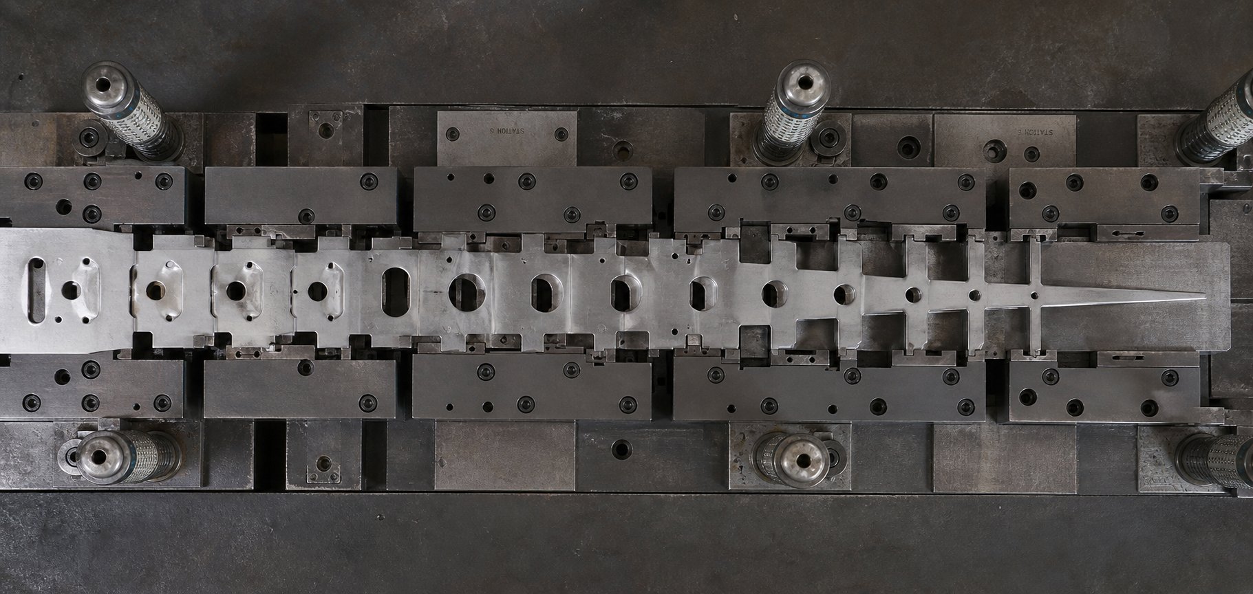
A carrier strip does not simply hold parts together. It transmits feeding force across every station, resists deflection under its own weight and the weight of partially formed parts, and maintains dimensional stability throughout the entire press stroke cycle. Every bypass notch you introduce changes that load-carrying picture. The question is not whether the notch affects carrier integrity, but how much, and whether the cumulative impact stays within acceptable limits.
Maintaining Carrier Strength Through Multiple Stations
Imagine a 14-station progressive die with negative bypass notches at stations 3, 5, 7, 9, and 11. Each notch removes a rectangular section from the carrier edge. At station 3, the carrier cross-section drops slightly. By station 11, five separate material removals have reduced the effective load-bearing width in different locations along the strip. The carrier that enters station 12 is measurably weaker than the one that entered station 1.
This cumulative carrier weakening from negative bypass notches creates a compounding structural problem. Carrier strength fundamentals show that the strip must resist bending forces proportional to the number of progressions multiplied by the part weight. If the carrier cross-section is reduced at multiple points, the weakest section governs the overall strip rigidity. One under-designed notch in a chain of five can become the failure point that buckles the strip or causes it to droop between lifters.
Die designers must balance clearance needs against this structural reality. Practical approaches include:
- Staggering negative notch locations between the left and right carrier edges so both sides are never weakened at the same station
- Reducing individual notch width to the minimum required clearance rather than using uniform oversized notches throughout
- Adding stiffening ribs or beads to the carrier between notch locations to recover some of the lost rigidity
- Switching to positive notches at downstream stations where cumulative material loss approaches the carrier strength limit
Positive bypass notches preserve the carrier cross-section entirely. The material stays attached, maintaining the full edge width at every station. This is their primary structural advantage in high-station-count dies. However, they introduce a different concern: stress concentrations at the coined areas. The plastic deformation that creates the displaced tab also work-hardens the surrounding material and creates a localized zone of residual stress. Under repeated strip flexing as the carrier lifts and lowers across cycles, these stress risers can become initiation sites for fatigue cracks, particularly in harder or less ductile materials.
The trade-off is clear. Negative notches reduce cross-section but leave the remaining material in its original condition. Positive notches retain cross-section but alter the material state at each coined zone. Neither approach is universally superior for carrier strip strength bypass notch design. The right choice depends on whether your specific application is more sensitive to cross-section loss or to fatigue loading at stress concentrations.
Material Flow and Deformation Patterns Around Notches
Bypass notches do not exist in isolation on the carrier. Adjacent stations often perform forming operations like draws, bends, or lances that depend on controlled material flow into the forming cavity. When a bypass notch sits near an active forming zone, it disrupts the uniformity of that flow.
Consider grain flow disruption near bypass notch cuts. When a negative notch is punched from the carrier edge, the shearing action severs the grain structure at the cut boundary. Material adjacent to that severed edge no longer has continuous grain support. If a forming station immediately downstream pulls material toward the notch location, the unsupported edge can tear, wrinkle, or form unevenly because the grain flow path has been interrupted. The material has nowhere to draw from at the notch void, creating an asymmetric flow pattern that shows up as uneven wall thickness or localized thinning in the formed feature.
Positive bypass notches produce a different pattern. The coining action compresses material in the notch zone, locally reducing thickness and introducing compressive residual stress in-plane. Material flow around bypass notches in a progressive die is affected because the coined area resists further deformation. Adjacent forming operations that try to stretch material through a previously coined zone encounter higher resistance in that localized region, which can redirect metal flow and create uneven strain distribution in the finished part.
These effects become significant under specific conditions:
- The bypass notch edge is within 5 mm of an active forming boundary
- The forming operation involves material draw or stretch that pulls toward the notch location
- The part geometry requires uniform wall thickness in areas adjacent to the carrier attachment
- The material is thin enough (below 0.8 mm) that localized grain disruption propagates further relative to the part dimensions
When these conditions converge, the bypass notch influences final part quality even though it never becomes part of the finished component. The residual stress patterns from a positive notch coin, or the grain discontinuity from a negative notch cut, extend into material that later forms the part edge or a near-edge feature. Parts trimmed close to the carrier attachment point carry those effects into the finished geometry.
Complex bypass notch configurations, particularly in multi-station progressive dies with tight carrier constraints, demand careful analysis of these interactions. Engineers working through carrier integrity challenges in dies with more than 8 or 10 stations often need to simulate material flow paths and verify that notch-induced disruptions do not propagate into critical forming zones. For design-heavy applications where bypass notch placement intersects with forming operations, lifter travel, and carrier strength simultaneously, specialized tooling engineering support can reduce iteration cycles. YICHEN's custom stamping die solutions address exactly this class of problem, offering die structure and material flow expertise for progressive dies where bypass notch design interacts with carrier integrity at every station.
The interplay between notch design and carrier behavior is a system-level concern. Every choice, from notch type to placement to depth, feeds into whether the strip survives the full die progression without degradation. But even well-designed notches can develop problems over thousands of production cycles, and recognizing those failure patterns early is what separates a stable process from one that generates scrap and downtime.
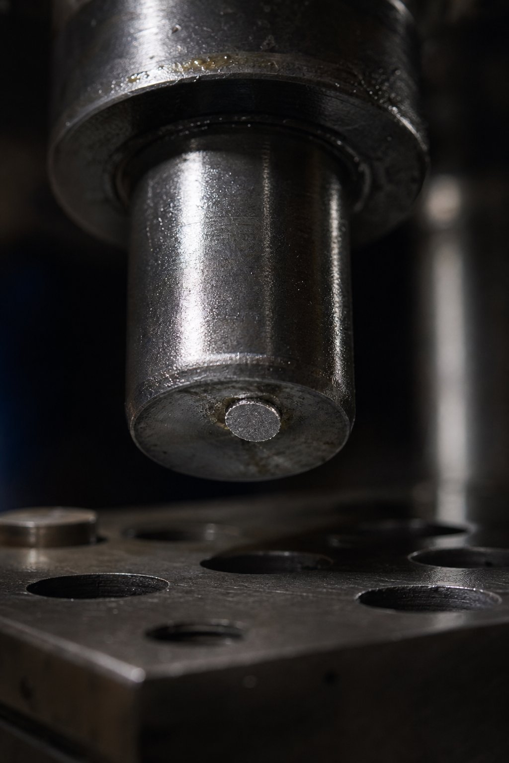
Troubleshooting Bypass Notch Failure Modes in Production
A bypass notch that performs flawlessly during tryout can develop problems thousands of cycles into a production run. Wear, thermal shifts, and material variability introduce conditions the original design did not anticipate. Recognizing how these failures present themselves, and tracing each symptom back to its root cause, is what keeps progressive dies running instead of sitting idle on the bench.
Three distinct failure categories account for the majority of bypass notch production issues: slug-related problems in negative notches, interference-driven misfeeds, and mechanical degradation of positive notch coins. Each category produces different symptoms, demands different diagnostic approaches, and responds to different corrective actions.
Slug Pulling and Burr Formation in Negative Bypass Notches
Every negative bypass notch generates a slug on every press stroke. Under normal conditions, that slug drops cleanly through the die matrix and exits into a scrap chute. When the slug sticks to the punch face during retraction instead of staying in the matrix, you have a slug pulling condition, and the consequences escalate fast.
A pulled slug can re-deposit onto the strip surface, the die face, or inside a forming cavity. If it lands on the strip and gets carried into the next station, a single slug can damage forming steels, distort parts, or crack punches across every downstream station. As die science research explains, the consequences of a pulled slug can be disastrous because one slug carried through a progressive die can cause damage to every station in the tool.
What causes bypass notch slugs to pull? Several mechanisms work alone or in combination:
- Vacuum effect: Slugs generated during punching develop slight curvature. Air trapped in the void between slug and punch face creates a partial vacuum during retraction. The tight seal around the punch perimeter prevents air from entering, and the suction holds the slug against the punch.
- Excessive cutting clearance: When punch-to-die clearance runs on the high side, the slug ends up slightly smaller than the matrix opening. It no longer has a press-fit interference to hold it in the die, so it can travel freely with the punch during withdrawal.
- Magnetism: Ferrous slugs cut from carbon steel or stainless strip can adhere to magnetized punches. Punches ground on magnetic surface grinders pick up residual magnetism that attracts the slug on every cycle.
- Worn or degraded ejector springs: Many bypass notch stations use spring-loaded slug ejectors to positively push the slug off the punch face. When those springs fatigue or break, the slug has no mechanical force counteracting the vacuum and friction holding it to the punch.
Bypass notch slug pulling troubleshooting starts with identifying which mechanism dominates. If slugs pull intermittently and the die runs ferrous material, check for residual magnetism first since it is the easiest to correct. A demagnetizer applied after every sharpening cycle eliminates this cause entirely. For vacuum-driven pulling, small air vents drilled through the center of the notch punch break the seal. For clearance-related issues, consider a reverse-taper retention button that holds slugs in compression within the matrix.
Burr formation is the second persistent issue in negative bypass notches. As the notch punch and die wear over tens of thousands of cycles, the effective cutting clearance gradually increases. The larger that clearance grows, the more material rolls over the die edge before fracture occurs, producing a progressively taller burr on the notch edge.
Why does this matter for bypass notch function? A burr that faces upward from the strip surface effectively reduces the clearance between the strip edge and the die component the notch is designed to bypass. A 0.1 mm burr on a notch originally designed with 0.3 mm of clearance margin reduces your effective margin by one-third. Over enough cycles, that burr growth alone can bring the strip into intermittent contact with forming steels or pilots during indexing.
Bypass notch burr formation corrective action follows two paths: restore the cutting clearance by sharpening the punch and die, or control burr direction during die design so burrs face downward away from potential interference surfaces. Orienting the notch punch to cut from the top surface of the strip pushes the burr to the bottom edge, where it projects away from overhead die components rather than toward them.
Misfeed Conditions Caused by Notch Interference
When a bypass notch fails to provide adequate clearance, the strip catches on a die component during indexing. The result is a misfeed: the strip does not advance the full programmed pitch, or it advances but with lateral displacement or angular skew. Either condition means the next press stroke hits an incorrectly positioned strip, producing scrap at best and die damage at worst.
A misfeed caused by bypass notch interference rarely appears as a single dramatic event. It typically builds gradually as conditions degrade over a production run. Recognizing the early indicators allows you to intervene before the condition escalates to die damage.
Diagnostic indicators that point to notch interference as the misfeed source include:
- Inconsistent progression marks: Check the strip between stations for witness marks left by pilots during correction. If pilot marks show varying depth or direction from stroke to stroke, the strip is arriving at inconsistent positions, suggesting it is catching and releasing unpredictably during indexing.
- Pilot hole elongation: When pilots must forcibly correct a strip that has not fully advanced, they push material at the pilot hole boundary beyond its elastic limit. Over repeated corrections, the pilot hole elongates in the feed direction. Oval pilot holes visible during strip inspection are a clear sign of feed interference upstream.
- Strip edge damage patterns: Look at the carrier edge directly at notch locations. Scraping marks, burnishing, or material smearing along the notch wall indicate the strip is rubbing against a die component during travel. The location and orientation of these marks tell you exactly which component is interfering.
- Intermittent sensor trips: If your die uses a misfeed detection sensor, intermittent trips that do not correspond to obvious feed problems often trace back to marginal notch clearance. The strip advances most of the time but hangs up occasionally when conditions align, such as when material runs slightly thicker or die temperature peaks.
Three root causes account for most interference misfeeds:
Insufficient notch depth from the start. The notch was dimensioned with inadequate margin, and any process variation, whether material thickness running at the high end of spec, slight thermal expansion, or minor burr buildup, pushes the clearance below zero. The fix is re-machining the notch station to increase depth, typically by 0.1 to 0.2 mm beyond the original specification.
Material buildup on die components. Lubricant residue, oxide particles, or fine metal shavings accumulate on lifters, forming steels, or pilot bodies over thousands of cycles. This buildup effectively increases the envelope of the component, reducing the clearance gap even though the notch itself has not changed. Regular cleaning schedules and filtered lubrication systems address this cause. Bypass notch wear diagnosis in a progressive die should always include measuring die component dimensions against baseline, not only notch dimensions.
Thermal expansion during sustained runs. Die components made from tool steel expand as friction and forming energy heat the die during production. A forming steel that measures 8.00 mm tall at ambient temperature may reach 8.03 mm after 2,000 continuous strokes at 300 SPM. That 0.03 mm expansion eats directly into your bypass clearance margin. High-speed dies benefit from a thermal expansion buffer factored into the original notch depth, or from warm-up procedures that allow dimensional stabilization before quality-critical production begins.
Tab Fracture and Positive Notch Coin Wear
Positive bypass notches avoid slug pulling entirely since there is no slug to pull. But they introduce their own failure mode: tab fracture. The coined tab that displaces below the strip plane remains attached to the carrier by a thin connection at its base. Under repeated bending cycles as the strip lifts and lowers over stock lifters, that connection fatigues.
Positive bypass notch tab fracture failure typically occurs under two conditions. First, when the coin depth is too aggressive relative to material thickness. Coining a tab to a depth exceeding 1.5 times the material thickness in low-ductility materials thins the base connection to a point where fatigue life drops dramatically. Second, when the tab undergoes repeated reverse bending as the strip flexes over lifters cycle after cycle. Even a modestly coined tab can fracture after millions of flex cycles if the strip path forces the tab through a bending range that exceeds the material's fatigue endurance limit.
When a tab fractures, it becomes loose debris inside the die. A small metal fragment rattling between die stations can embed in forming surfaces, scratch parts, or jam between moving components. Unlike slug pulling, which deposits material on the strip surface, a fractured tab produces an irregularly shaped chip that can wedge into tight clearances and resist ejection by air blow-off systems.
Coin punch wear introduces a subtler problem. The punch that creates a positive bypass notch is a precision ground tool subject to the same wear mechanisms as any other die component. Over production life, the working face of the coin punch wears flat, reducing the effective penetration depth. A punch originally ground to produce 1.2 mm of coin depth may deliver only 0.9 mm after 500,000 strokes. That gradual reduction means positive notch clearance degrades silently until the strip begins catching on die components, often without any visible indicator until misfeeds start occurring.
Monitoring positive notch function requires periodic measurement of actual coined depth on the strip itself. Pull sample strips at defined intervals and measure the tab displacement with a depth micrometer or optical comparator. When measured depth drops within 0.1 mm of the minimum functional clearance, schedule coin punch maintenance or replacement before the next production run.
Failure Mode Troubleshooting Checklist
Use the following checklist to quickly pair each failure mode with its most likely root cause and the corrective action that resolves it:
- Slugs sticking to notch punch: Root cause is vacuum effect, magnetism, or excessive cutting clearance. Corrective action: add air vents to punch face, demagnetize after sharpening, install reverse-taper slug retention button, or verify and restore proper punch-to-die clearance.
- Increasing burr height on notch edges: Root cause is punch and die wear increasing effective clearance. Corrective action: sharpen punch and die to restore original clearance, or orient punch direction to push burrs away from interference surfaces.
- Intermittent misfeeds at notch stations: Root cause is marginal clearance combined with process variation (material thickness, thermal expansion, debris buildup). Corrective action: increase notch depth by 0.1 to 0.2 mm, implement die cleaning intervals, add thermal stabilization buffer to notch dimensioning.
- Pilot holes elongating in feed direction: Root cause is incomplete strip advancement due to notch interference forcing pilot over-correction. Corrective action: identify and resolve the specific interference point by inspecting notch edges for scraping marks, then restore clearance.
- Fractured coin tabs creating loose debris: Root cause is excessive coin depth in low-ductility material or fatigue from repeated strip flexing over lifters. Corrective action: reduce coin depth to below 1.5x material thickness, add a radius to the coin base to reduce stress concentration, or redesign lifter positions to minimize flex at coined zones.
- Positive notch clearance degrading over production life: Root cause is coin punch face wear reducing penetration depth. Corrective action: measure coined depth on sample strips at defined intervals, sharpen or replace coin punch when depth drops within 0.1 mm of minimum functional clearance.
- Strip edge smearing or burnishing at notch walls: Root cause is the strip rubbing a die component during indexing due to inadequate notch width or lateral strip misalignment. Corrective action: widen notch by the measured interference amount plus margin, verify strip tracking and guide alignment.
Each of these failure modes is detectable before it escalates to die damage, but only if you know what to look for. Building these inspection points into your preventive maintenance schedule transforms bypass notch troubleshooting from reactive firefighting into a predictable maintenance task. That shift from reactive to proactive is ultimately what connects individual notch performance to overall die uptime and part quality across the full production lifecycle.
Bypass Notch Design Impact on Part Quality and Production Stability
Detecting and correcting failure modes keeps a die running. But the deeper question is whether those failures needed to happen at all. In most cases, bypass notch problems that surface during production trace back to a design decision made weeks or months earlier. The type you selected, the dimensions you specified, where you placed each notch, and how you balanced carrier integrity against clearance needs all converge into a single outcome: does the die run stable, or does it generate scrap, downtime, and frustration?
Connecting Bypass Notch Decisions to Part Quality Outcomes
Every bypass notch decision feeds forward into measurable production metrics. Consider how the chain works:
- Type selection determines whether the carrier retains full cross-section (positive) or loses material at each station (negative). That choice directly governs strip rigidity at the feed line, which controls feed accuracy, which determines whether pilots can register the strip within tolerance. Strip feed reliability and bypass notch optimization start here, at the earliest design decision.
- Dimensioning sets the clearance margin that separates smooth indexing from intermittent interference. An under-dimensioned notch does not just cause a misfeed. It forces pilots to over-correct, elongates pilot holes progressively, and introduces cumulative positional drift that shows up as feature-to-feature variation on finished parts.
- Placement relative to pilot holes and feed zones controls whether the strip registers accurately at every station. A notch that distorts the pilot datum by even 0.03 mm compounds across 10 or 12 stations into positional errors that exceed part tolerance. Defect rates climb not because the forming tools are worn, but because the strip arrives at each station slightly mislocated.
- Carrier balance determines whether the strip survives the full progression without excessive deflection or fatigue cracking. A carrier that buckles at station 9 because cumulative notch removals weakened it beyond its structural limit does not just produce one bad part. It stops the press, requires strip clearing, and consumes maintenance time that erodes overall die uptime.
These are not isolated variables. They interact. A positive notch that preserves carrier strength but springs back excessively because the material was too hard creates the same interference condition as a negative notch that was undersized. A perfectly dimensioned negative notch placed too close to a pilot hole produces registration errors that no amount of clearance margin can fix. The bypass notch design lifecycle works as a system, and treating any single parameter in isolation invites downstream failures.
Progressive die bypass notch production validation confirms whether that system holds together under real conditions. Validation typically involves running sample strips at production speed, measuring coined depth or notch clearance at each station, checking pilot hole geometry after several hundred cycles, and verifying strip tracking through the full die length. Engineers who validate notch performance during tryout rather than waiting for production problems to surface avoid the most expensive failure mode of all: unplanned downtime during a committed production run.
What separates stable progressive dies from problematic ones is rarely the sophistication of the forming operations. It is often the quality of the seemingly minor features, like bypass notches, that enable everything else to function predictably. Engineering decisions made at the design stage dictate up to 80% of total production cost, and bypass notch configuration is part of that equation.
Bypass notches are not passive clearance features. They are active contributors to process stability. Treat their design as a system-level decision integrated with strip layout, carrier engineering, and pilot strategy rather than an afterthought resolved after forming stations are finalized.
Engineering Resources for Progressive Die Design
Bypass notch design lifecycle best practices extend beyond what any single article can cover in full detail. Real-world applications involve material grades with unpredictable springback behavior, strip layouts constrained by part geometry on three sides, and station counts that push carrier integrity to its limits. Tooling engineers working through these challenges benefit from resources that address the full system: die structure, component interaction, clearance optimization, and material flow in combination rather than in isolation.
Where can you go deeper? Start with your own strip layout simulations. Model the carrier cross-section at every station after all notches, trims, and piercings are applied. Verify that the minimum remaining section meets your rigidity requirements for the full progression length. For positive notches, run springback compensation analysis specific to your material grade and thickness, because generic multipliers rarely account for batch-to-batch variation in real production coils.
For engineers facing design-heavy challenges where bypass notch configuration intersects with lifter travel, punch access, burr control, and progressive die structure simultaneously, custom tooling support shortens the path from concept to validated design. YICHEN's stamping die solutions offer exactly this kind of integrated engineering support, covering die structure, clearance optimization, material flow analysis, and bypass notch design within the context of the complete progressive die system. Their focus on connecting tooling engineers to solutions for complex multi-station dies, including lifter design, punch configuration, and carrier integrity, aligns directly with the system-level approach this article advocates.
Whether you are designing your first bypass notch or refining a 20-station die that demands both positive and negative notches working in concert, the principle remains the same: every notch is a design decision with downstream consequences. Get the system right at the design stage, validate it during tryout, and monitor it through production life. That discipline is what turns bypass notches from a potential failure source into a reliable foundation for strip feed reliability and consistent part quality across millions of press cycles.
Frequently Asked Questions About Bypass Notches in Stamping Dies
1. What is the difference between negative and positive bypass notches in progressive dies?
A negative bypass notch removes material from the carrier strip edge through a punch-and-die cutting action, leaving an open gap that provides clearance. A positive bypass notch deforms material downward out of the strip plane using a coining or embossing operation without removing any material. Negative notches generate scrap slugs and reduce carrier cross-section, while positive notches preserve full edge width but are limited in achievable clearance depth by material springback. The choice between them depends on carrier strip width, material thickness and ductility, station count, and required clearance depth.
2. How do you determine the correct bypass notch depth for a progressive stamping die?
Bypass notch depth is calculated based on the height of die components the strip must clear during indexing, including forming steels, lifter travel distance, and pilot pin diameter. For negative notches, depth typically ranges from 1.5 to 2.5 times the stock thickness. For positive notches, coined depth usually falls between 1.0 and 1.5 times material thickness to avoid cracking. Additional factors include springback compensation for positive notches (typically 10-25% overbuild), thermal expansion buffers for high-speed dies, and burr height allowances for negative notches. The goal is minimum clearance that guarantees free strip passage plus a controlled safety margin.
3. What causes bypass notch slug pulling and how do you fix it?
Slug pulling in negative bypass notches occurs when the cut slug adheres to the punch during retraction instead of staying in the die matrix. Four primary causes drive this problem: vacuum effect between the slug and punch face, excessive punch-to-die clearance making the slug undersized relative to the matrix opening, residual magnetism in the punch attracting ferrous slugs, and worn or broken ejector springs. Corrective actions include drilling air vents through the punch center to break vacuum, demagnetizing punches after every sharpening cycle, installing reverse-taper slug retention buttons, and restoring proper cutting clearance through punch and die maintenance.
4. When should you use positive bypass notches instead of negative ones?
Positive bypass notches are the better choice when carrier strip edge stock is less than 4 times the material thickness, when the die has more than 8 stations requiring bypass clearance (to avoid cumulative carrier weakening), when the material is thin and ductile with elongation above 20%, when the strip layout uses stretch web carriers near notch zones, or when scrap management constraints make slug disposal difficult. Negative notches are preferable for thick or hard materials above 1.5 mm or 40 HRC that resist coining, when required clearance exceeds 2 times material thickness, or when long production runs make springback compensation unreliable over time.
5. How close can a bypass notch be placed to a pilot hole without causing registration errors?
The standard recommendation is a minimum distance of 3 times the material thickness between the nearest bypass notch edge and the center of the closest pilot hole. For critical applications requiring tolerances below plus or minus 0.05 mm, increasing this buffer to 5 times material thickness provides additional protection against stress-induced distortion. Both negative notches (which redistribute stress through shearing) and positive notches (which radiate coining force outward) can distort pilot hole geometry if placed too close, causing registration errors that compound through every downstream station. When layout constraints prevent adequate spacing, relocating the pilot hole to the opposite carrier edge is a viable alternative.


