


What Metal Stamping Tool and Die Repair Really Involves
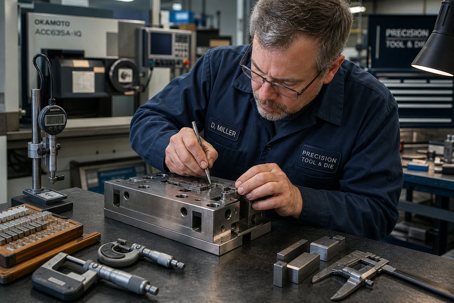
Metal stamping tool and die repair is the corrective restoration of damaged, worn, or malfunctioning die components to their original working condition. It ranges from minor in-press adjustments, like replacing a chipped punch at the station, to major bench repairs requiring full disassembly, welding, re-machining, and reassembly of critical die sections. Unlike scheduled preventive maintenance, repair responds to a failure that has already occurred or is actively producing defective parts.
Defining the Scope of Die Repair Work
Think of die repair on a severity scale. At one end, you have quick corrective actions: swapping a broken pilot, touching up a cutting edge with a stone, or shimming a misaligned component. At the other end, you're pulling the die to the bench for weld buildup on cracked die sections, EDM work on precision features, or complete regrinding of form stations that have drifted out of tolerance. The common thread is that something has failed or degraded beyond acceptable limits, and production cannot continue until it's corrected.
Preventive maintenance preserves a die in its current working state through scheduled tasks like sharpening, lubrication, and inspection. Die repair restores a die that has already failed or degraded beyond acceptable production tolerances. Confusing the two leads to inaccurate cost tracking and underfunded maintenance programs.
Many manufacturers intermix these two cost categories, making it nearly impossible to understand where their tooling budget actually goes. Separating repair costs from die maintenance costs is the first step toward reducing both.
Who Performs Die Repair and Where It Happens
Die repair falls to toolmakers, die maintenance technicians, and in some shops, experienced press operators handling minor corrections at the machine. More involved work moves to the toolroom bench, where technicians have access to surface grinders, welding equipment, and precision measurement tools. Major rebuilds may go to external tool and die shops with specialized capabilities like wire EDM or vacuum heat treatment.
Why Repair Skills Matter for Production Stability
Every unplanned die failure carries hidden costs beyond the repair itself: machine downtime, idle operators, quality holds, expedited shipments, and scrap. A skilled repair technician who can accurately diagnose a failure mode and execute a lasting fix, rather than a band-aid, directly protects production throughput. The difference between a shop that firefights constantly and one that runs stable schedules often comes down to the quality of its die repair execution.
The real challenge, though, isn't just fixing what broke. It's understanding why it broke in the first place, and that starts with knowing how to read the failure.
Common Die Failure Modes and Root Cause Diagnosis
A cracked punch or a galled draw station doesn't just appear out of nowhere. Every failure mode has a mechanism behind it, a set of visual clues it leaves behind, and a typical location where it shows up in the die geometry. When you can read those clues accurately, you move from reactive firefighting to targeted die failure root cause analysis, and that's where real stamping die maintenance begins.
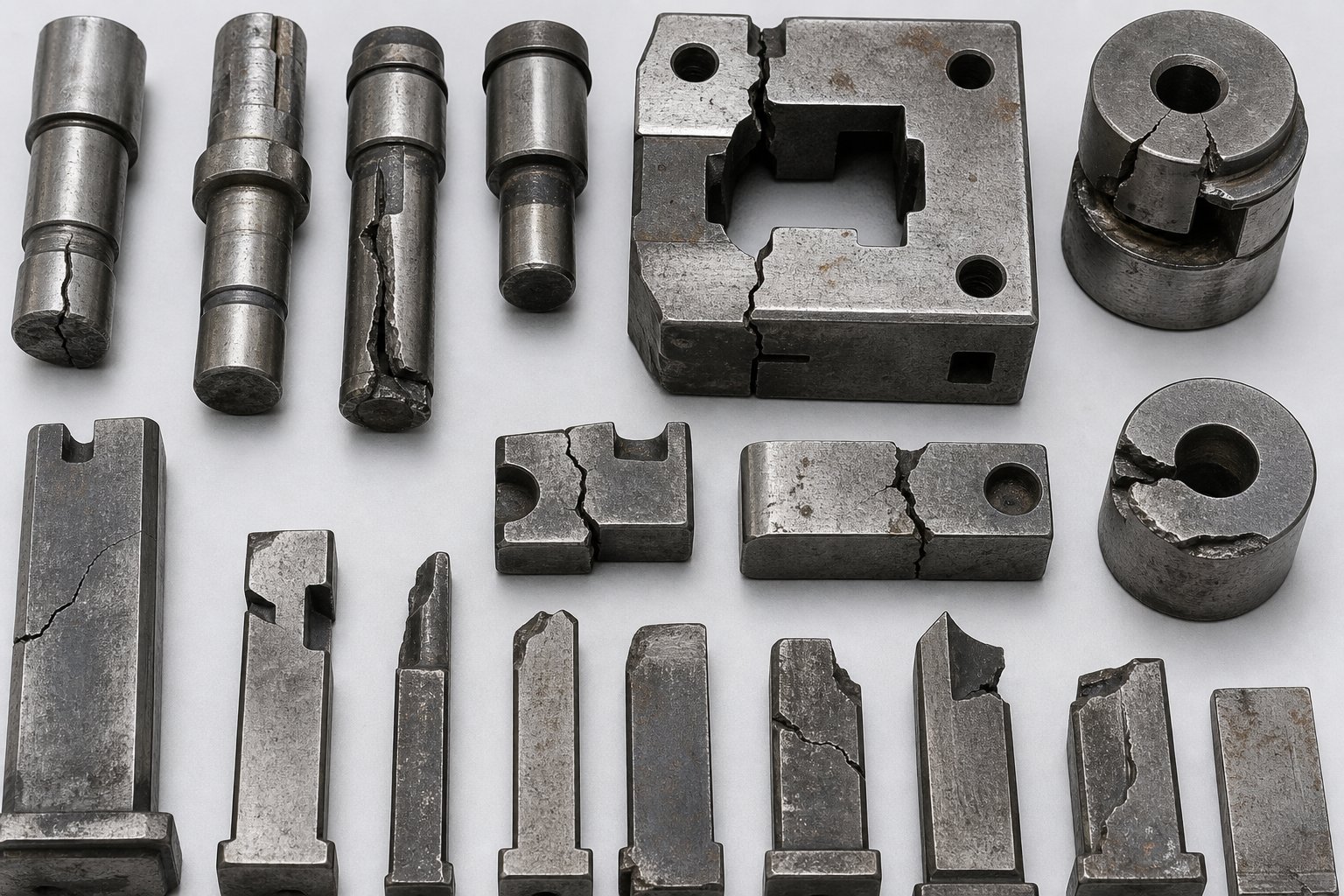
Five primary failure modes account for the vast majority of tooling damage in cold work stamping: wear, plastic deformation, chipping, cracking, and galling. Each behaves differently depending on the die material, the sheet metal being processed, and the operational loads involved. Let's break them down individually.
Fracture and Cracking Failure Patterns
Cracking occurs when operating stress levels exceed the fracture toughness of the tool material. Imagine a sharp corner on a trim steel or a punch with an abrupt cross-section change. These geometric stress concentrators act as crack initiation sites. Once a crack nucleates, it propagates under cyclic loading until the component fractures entirely, sometimes catastrophically.
You'll typically find cracking at sharp internal corners, around bolt holes in thin die sections, at the junction of thick and thin cross-sections, and along grinding marks left from previous rework. Visual indicators include a visible crack line (often highlighted by penetrant dye during inspection), a clean fracture surface with characteristic chevron marks pointing back to the origin, or sudden catastrophic breakage during a press stroke.
Chipping is related but distinct. It happens when operating stresses exceed the fatigue strength of the tool steel at sharp cutting edges. Microcracks form in the high-contact zone, propagate laterally, and eventually lift out small pieces of material along the edge. Chipping is especially common on piercing punches and trim steels running higher-strength sheet metals like dual-phase or TRIP steels, where contact forces can be up to four times higher than with mild steel.
In progressive dies, chipping tends to concentrate on the first few pierce stations because they experience the most cumulative hits. Transfer dies see cracking failures more often at curl stations or form stations where mechanical overload from work-hardened material stresses the tooling beyond its toughness limits. Compound dies, with their tight geometry and simultaneous cutting actions, are prone to cracking around the die button edges where multiple stress paths converge.
Wear and Galling Mechanisms
Wear is the gradual loss of material from the tooling surface caused by sliding contact with sheet metal. Two types dominate in stamping operations:
- Abrasive wear - Hard particles or hard phases in the sheet metal (oxides, carbides, or work-hardened surface layers) plow into the tool surface, removing material progressively. You'll see it as uniform polishing or grooving on draw radii, punch faces, and stripper surfaces.
- Adhesive wear - Friction and heat from sheet metal sliding across the tool surface create micro-welds between surface peaks (asperities). Continued motion tears small fragments from the weaker surface. These fragments can re-deposit on either surface, creating raised spots that then score subsequent parts.
Galling represents the severe end of adhesive wear. It's a physical and chemical adhesion of sheet metal to the die surface that builds up progressively. Once galling starts, it accelerates: the buildup creates rougher contact, which generates more friction, which transfers more material. You'll recognize it as lumpy, irregular buildup on form stations, draw radii, or anywhere the sheet metal slides under high pressure.
Progressive die wear patterns differ by station function. Pierce punches wear primarily on their cutting edges and flanks. Form stations wear on radii and contact faces. In transfer dies, the shell surfaces and locating features wear from repeated part insertion and extraction. Draw operations in any die type experience the most aggressive galling on bead radii and punch noses where contact pressure and sliding distance are highest.
Misalignment and Timing Failures Across Die Types
Misalignment failures don't originate from the die material itself. They come from positional errors between upper and lower die halves, worn guide components, press deflection, or improper setup. The result is uneven loading, off-center cutting, and accelerated wear on one side of a station.
In progressive dies, misalignment often shows up as uneven burr height across a cut edge, or pilots that begin shaving the strip. The tight station-to-station pitch means even small feed errors compound into timing failures where punches hit partially unsupported material. Transfer dies face different challenges: part locating in each station depends on accurate finger placement, and worn or misadjusted transfer mechanisms create positional errors that load the die asymmetrically. Compound dies, where multiple operations happen simultaneously in one stroke, are particularly sensitive because the internal timing between punch and die button has no room for positional drift.
Plastic deformation, the fifth failure mode, occurs when contact stress from the sheet metal exceeds the compressive yield strength of the tool material. You'll see it as localized sinking, mushrooming, or rounding of sharp features. It's most common on undersized punches, insufficiently hardened die sections, or tooling running material grades harder than originally specified.
| Failure Type | Common Causes | Visual Indicators | Affected Die Components |
|---|---|---|---|
| Cracking | Stress concentrators, improper heat treatment, overload, abrupt cross-section changes | Visible crack lines, clean fracture surfaces, catastrophic breakage | Trim steels, form sections, die blocks at sharp corners |
| Chipping | Cyclic fatigue at sharp edges, insufficient toughness, high-strength sheet metal | Small pieces missing along cutting edges, rough or scalloped edge profile | Pierce punches, trim steels, blanking dies |
| Abrasive Wear | Hard particles in sheet, high contact pressure, insufficient die hardness | Polished or grooved surfaces, gradual edge rounding, dimensional drift | Draw radii, punch faces, stripper plates, form stations |
| Galling / Adhesive Wear | High friction, inadequate lubrication, poor surface finish, galvanized coatings | Irregular material buildup, scoring marks, rough lumpy deposits | Draw beads, punch noses, form radii, blank holder surfaces |
| Misalignment | Worn guides, press deflection, improper setup, feed errors | Uneven burr, off-center slug marks, one-sided wear patterns | Guide pins, bushings, pilots, die shoes, transfer fingers |
| Plastic Deformation | Contact stress exceeding yield strength, under-hardened tooling, material upgrade without die review | Mushroomed edges, sinking, rounding of previously sharp features | Small punches, die buttons, form post radii |
These failure modes rarely exist in isolation. Adhesive wear can initiate chipping by creating surface irregularities where microcracks nucleate. Misalignment accelerates one-sided wear, which eventually leads to chipping or cracking. Reading the primary failure mode correctly, rather than just treating the visible symptom, is what separates effective die repair and maintenance from a cycle of repeat breakdowns.
The tooling tells you what went wrong. But the parts coming off the press tell you something went wrong first, often before anyone opens the die. Connecting those part-level quality signals back to specific die conditions is the next diagnostic skill worth developing.
Tracing Part Defects Back to Die Conditions
Your quality team flags a problem: burrs on a trimmed edge, a hole drifting out of position, or scratch marks running down a drawn surface. Before anyone pulls the die, the part itself is already telling you what's wrong inside the tooling. The trick is learning to read it. Effective stamping die troubleshooting defects starts not at the bench, but at the inspection table, where the defect pattern points directly to the die condition that caused it.
Here's a practical diagnostic framework any die maintenance technician can follow:
- Observe the defect on the part: identify its type, severity, and exact location.
- Trace the defect back to the responsible station using strip layout or part orientation.
- Inspect that specific station for the corresponding die condition: worn edge, loose component, buildup, or dimensional shift.
This three-step approach eliminates guesswork. Instead of pulling the entire die for a general inspection, you arrive at the toolroom bench already knowing where to look and what to look for.
Burrs and Edge Defects as Wear Indicators
Burrs are the most common early warning that a stamping tool repair is overdue. When a cutting edge dulls, rounds over, or chips, it can no longer produce the clean shear fracture that gives you a smooth cut edge. Instead, the material tears rather than shears, leaving raised material on the part edge.
What makes burr defect die repair effective is understanding that not all burrs point to the same root cause. The burr's characteristics tell you exactly what happened:
- Uniform burr around the entire cut edge - indicates general cutting edge wear. The punch or die section needs sharpening. This is the most straightforward scenario.
- Burr on one side only - signals misalignment between punch and die. The clearance is uneven, with the tight side producing a clean edge and the loose side generating burr. Check guide pins, bushings, or press alignment.
- Intermittent or localized burr - points to chipping or localized edge damage at that specific area of the cutting profile. Inspect the edge under magnification for missing material.
- Excessive burr height exceeding 0.1mm with rough tear - suggests the clearance between punch and die is too large, or the edge has collapsed significantly. Re-grinding alone may not restore proper geometry if material loss is severe.
- Burr with rollover on the opposite face - indicates slug pulling or material dragging, often caused by a dull edge combined with inadequate stripper pressure or slug retention issues.
Each of these burr signatures maps to a different repair action. Sharpening solves the first. Realignment solves the second. Edge repair or replacement addresses the third and fourth. Treating all burrs as a simple sharpening problem is why some dies come back from the toolroom and fail again within hours.
Dimensional Drift and Its Die-Side Causes
When part dimensions begin creeping out of tolerance gradually over a production run, you're looking at die wear diagnosis from part quality data. Dimensional drift rarely appears suddenly. It accumulates over thousands of hits until the part crosses the tolerance boundary, and by then the die condition may have degraded significantly beyond where it first left the acceptable zone.
Common dimensional defects and what they reveal about the die:
- Hole position shifting - worn or loose pilots failing to locate the strip accurately, or feed system inconsistency allowing the strip to drift between stations.
- Bend angle opening up over time - form punch or die insert wearing on the radius, reducing effective contact. Also check for loose heel blocks or backing plates that allow the form station to deflect under load.
- Overall part profile growing larger - blanking or trim edges wearing inward, effectively making the cut profile larger. The die cavity is eroding and needs re-machining or insert replacement.
- Flange length shortening - draw radius wear increasing the effective radius, which pulls more material into the form and shortens the resulting flange.
- Inconsistent dimensions piece-to-piece - loose components rather than wear. Bolts backing out, inserts shifting, or a cracked die section moving under load. This pattern demands immediate attention because it typically worsens rapidly.
The critical insight here is timing. Gradual drift means wear, while sudden change means something broke, loosened, or shifted. That distinction determines whether your repair is a controlled regrind or an emergency intervention.
Surface Quality Issues That Signal Galling or Buildup
Surface defects on formed or drawn parts provide a direct window into what's happening at the die-to-material interface. Unlike dimensional issues, surface problems are often visible immediately and tend to worsen quickly once they start.
- Linear scratch marks in the draw direction - galling has begun on the corresponding die surface. Material has transferred from the sheet to the tooling and is now scoring every subsequent part. The longer you run, the deeper the scratches become.
- Random surface marks or dents - debris trapped between the die and strip. Slugs pulling back through, loose chips from a damaged edge, or environmental contamination. Cleaning the die resolves it temporarily, but the source must be found.
- Orange peel texture on formed surfaces - typically a material issue rather than a die condition, but if it appears suddenly on a previously clean-running job, check for roughened die surfaces from early-stage galling or corrosion.
- Splitting or tearing at draw radii - the draw radius has worn too sharp or too rough, restricting material flow. Alternatively, the blank holder force has increased due to worn or contaminated bead surfaces. Either way, the material cannot flow freely into the die cavity and fractures instead.
- Wrinkling at flanges or unsupported areas - insufficient blank holder pressure, often caused by worn pressure pads, fatigued springs, or nitrogen cylinder pressure loss. The material buckles where it should be constrained.
Surface issues escalate fast. A minor galling mark today becomes a deep score tomorrow, which becomes a cracked draw station next week once the buildup creates enough localized stress. Early detection and prompt stamping tool repair at the first sign of surface degradation prevents cascading failures that turn a 30-minute polish into a multi-day rebuild.
Reading part defects this way transforms quality data into maintenance intelligence. But knowing what's wrong is only half the equation. The other half is knowing how to fix it correctly, with the right technique for each specific failure mode, so the repair lasts rather than buying you just another few hundred hits before the same problem returns.
Step-by-Step Repair Techniques for Common Die Failures
Diagnosing the failure mode correctly puts you halfway to a lasting fix. The other half is executing the right repair technique with the right procedure. A weld repair done carelessly creates a harder problem than the original crack. A grinding pass taken without understanding how much material to remove leaves you with a die that won't hold tolerance. Technique selection depends on the failure mode, the die material, and the tolerances that station needs to hold. Let's walk through the primary die reconditioning methods and when each one applies.
One critical point before diving in: temporary fixes performed under the ram, like stoning an edge or shimming a worn section without pulling the die, almost always create double maintenance work. They mask the real condition, allow further degradation, and often introduce new problems like uneven clearances or stress risers. Proper bench repair takes more time upfront but eliminates the cycle of repeated quick fixes that eat more total hours than doing it right once.
Weld Repair Procedures for Cracked and Chipped Components
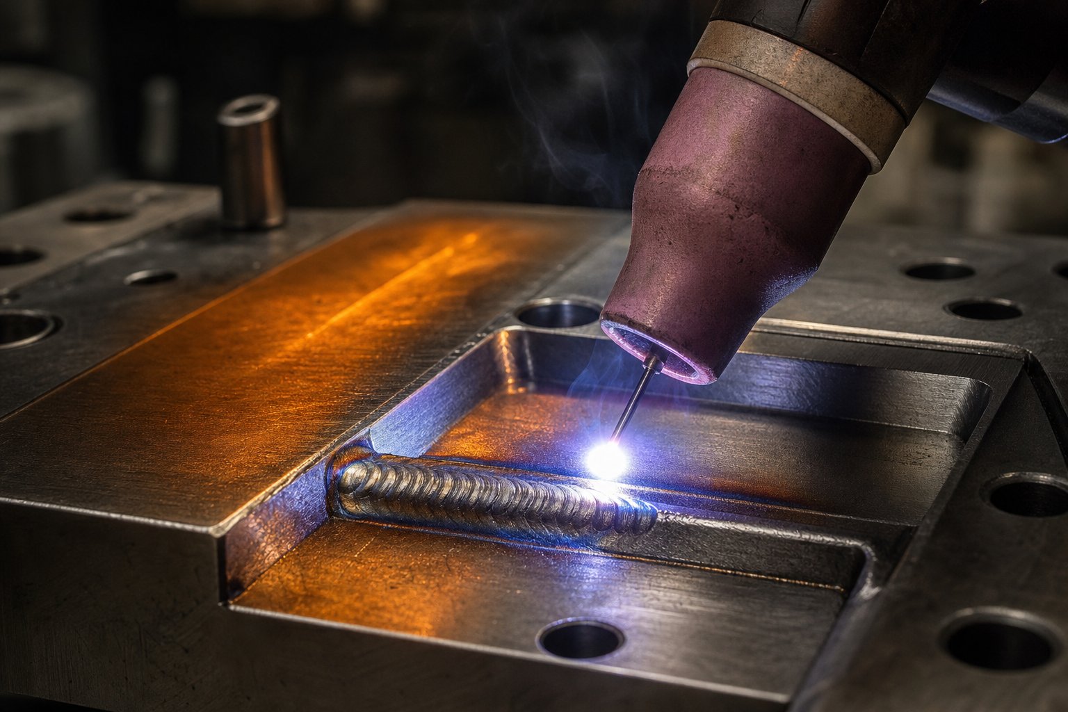
Weld repair applies when die components have cracked, chipped, or lost material that can't be restored by simple grinding. It's one of the most powerful die reconditioning methods available, but also the one most frequently botched. A proper die weld repair procedure follows a strict sequence, and skipping steps is where most failures originate.
When is welding the right call? Use it for cracked die sections where replacement isn't immediately available, chipped cutting edges with material loss deeper than grinding can address, worn form radii that need material buildup before re-machining, and damaged locating surfaces that need dimensional restoration.
The equipment required includes a TIG or micro-TIG welding setup for precision deposits, appropriate filler rods matched to the base tool steel, a preheat oven or torch capable of controlled heating, and temperature-indicating crayons or pyrometers for monitoring. According to principles outlined by MetalForming Magazine, successfully welding tool steels depends on a properly developed welding procedure and careful electrode selection that matches the heat treatment of the die steel being repaired.
Key procedural guidelines for weld repair:
- Identify the tool steel - you cannot select the correct filler rod without knowing the base material. D2, A2, S7, and M2 each require different approaches.
- Prepare the joint - grind away all cracked or damaged material until you reach sound base metal. For worn cutting edges, grind at least 3mm (1/8 inch) below the final desired surface to allow uniform weld depth.
- Preheat the workpiece - this is non-negotiable for tool steels. Preheat temperature depends on the steel type but typically ranges from 200°C to 540°C. Welding cold tool steel guarantees cracking in the heat-affected zone.
- Deposit weld metal in controlled passes - for deep repairs requiring multiple passes, start at the bottom and fill gradually. Peen the weld metal while hot to minimize shrinkage, warping, and cracking.
- Post-heat and temper - after welding, allow the component to cool slowly, then reheat to the recommended tempering temperature for that tool steel and electrode combination.
Common mistakes that cause repeat failures: welding without preheat, using mismatched filler material, failing to grind out all damaged material before welding (trapping defects beneath new deposits), and skipping post-weld tempering. Any of these shortcuts guarantees the repair will crack again, often sooner than the original failure.
Grinding and Re-Machining Worn Surfaces
Stamping die grinding and sharpening is the most frequent repair activity in any toolroom. It addresses the natural wear that accumulates on cutting edges, form surfaces, and contact faces over production runs. The key question every technician faces is simple: how much material do you remove?
The answer: keep removing material until all wear-affected area disappears. That sounds obvious, but under-grinding is one of the most common mistakes. If you leave even a thin band of worn material at the cutting edge, the die will dull again almost immediately because the rounded edge profile hasn't been fully restored to a sharp intersection.
Here's the sequential procedure for the most common repair scenario, cutting edge restoration through surface grinding:
- Remove the component from the die assembly and clean it thoroughly. Remove any burrs, galling deposits, or debris that would interfere with grinding.
- Inspect the cutting edge under magnification to assess wear depth and identify any chipping that extends deeper than normal wear.
- Mount the component on the surface grinder with proper fixturing to ensure the ground surface will be parallel to the original datum.
- Take light passes (0.01-0.025mm per pass) using an appropriate grinding wheel for the tool steel hardness. Flood coolant is essential to prevent thermal damage to the hardened surface.
- Continue passes until visual inspection confirms all wear marks and edge rounding have been removed, revealing fresh, sharp cutting geometry across the entire profile.
- Deburr the component, check critical dimensions with micrometers or gauge blocks, and verify flatness with a surface plate and indicator.
- If the component has been ground below its minimum height (the point where shims can no longer compensate for material removal), flag it for replacement rather than returning it to service undersized.
Remember that a matrix wears slower than a punch, so the amount of material removed from mating components won't be equal. Grind each part only as much as it needs. Excessive material removal shortens component life unnecessarily.
For punches with ejector pins, either remove the pins and grind the components separately, or insert a keeper key through the side vent hole to retain the pin at the correct extension while grinding. Either way, the ejector pin must extend the correct distance from the punch face after sharpening, or you'll have slug-pulling problems immediately.
One hazard that ruins otherwise good grinding work: excessive heat buildup. If you see discoloration (blue or straw-colored marks) on the ground surface, you've drawn the temper out of the hardened steel. That softened zone will wear at an accelerated rate. Use adequate coolant flow, lighter passes, and a properly dressed wheel to prevent thermal damage.
EDM and Specialty Techniques for Precision Restoration
When conventional machining can't reach a damaged area, or when the geometry is too complex for manual grinding, EDM die repair techniques become essential. Electrical Discharge Machining removes material through controlled spark erosion, working regardless of the workpiece hardness. This makes it ideal for fully hardened die components that can't be conventionally machined without annealing first.
Two EDM methods apply to die repair:
- Sinker EDM - uses a shaped electrode (typically graphite or copper) to erode a cavity or profile into the workpiece. In repair applications, sinker EDM can restore complex cavity shapes, remove broken taps or drills stuck in die components without causing additional damage, and rebuild intricate form details that grinding cannot access.
- Wire EDM - uses a thin wire electrode to cut precise profiles through the full thickness of the workpiece. Ideal for cutting new inserts, adjusting trim profiles, or re-cutting punch geometries that have worn beyond grinding limits.
EDM excels in situations where you need tight tolerances (within 0.005mm) on hardened surfaces, complex internal geometries that no grinding wheel can reach, or delicate thin sections where mechanical cutting forces would cause deformation. The trade-off is speed. EDM is inherently slower than grinding, so it's reserved for precision restoration work rather than routine sharpening.
Beyond welding, grinding, and EDM, two additional techniques round out the die repair toolkit:
- Re-coating - applying surface treatments like titanium nitride (TiN) or titanium carbonitride (TiCN) after grinding restores wear resistance and reduces galling tendency. Re-coating extends the interval between sharpenings but requires that the surface be properly prepared and free of any grinding damage.
- Re-machining - for form stations that have worn beyond grinding recovery, CNC milling or jig grinding can restore the original profile. This requires the die section to be annealed first, re-machined, then re-hardened and tempered back to service hardness. It's essentially rebuilding the component, and the decision to re-machine versus replace comes down to lead time and cost.
Technique selection isn't arbitrary. Match the repair method to the failure mode: grinding for surface wear and dull edges, welding for material loss and cracking, EDM for precision features and inaccessible geometry, re-coating for galling prevention, and re-machining for profile restoration beyond grinding limits. Choosing the wrong method, or applying the right method with poor procedure, turns a single repair into a recurring failure.
Executing the mechanical repair correctly is essential, but it's only part of producing a durable result. What happens to the metallurgy of that tool steel during and after repair, particularly the thermal cycles introduced by welding and grinding, determines whether your fix lasts for 500,000 hits or fails again in 5,000.
Heat Treatment and Material Considerations During Repair
A weld deposit that looks clean on the surface can still crack within a few thousand press strokes. A ground surface that measures flat and sharp can still wear prematurely if its subsurface hardness was compromised during the repair. The mechanical work of fixing a die component is visible and measurable. The metallurgical work, the tool and die treatment that happens at the thermal level, is invisible until it fails. And it fails often, because this is the step most commonly skipped under production pressure.
Skipping heat treatment is the single most common cause of weld repair failure in die components. A metallurgically unsound repair that looks good on the bench will fail faster than the original damage it was meant to fix.
Understanding why thermal management matters, and what happens when you ignore it, is the difference between a repair that lasts the life of the program and one that buys you a week before you're pulling the die again.
Pre-Heat and Post-Weld Thermal Protocols
When you strike an arc on a hardened tool steel without preheating, you create an extreme thermal gradient. The weld pool is molten while the surrounding base metal remains near ambient temperature. As the weld cools, it contracts against rigid, cold material that resists movement. The result is locked-in residual stress concentrated in a narrow band called the heat-affected zone (HAZ). In tool steels hardened to 58-62 HRC, this zone becomes brittle martensite, a microstructure that is extremely hard but has almost zero tolerance for tensile stress or impact. Cracks initiate there, often within hours of the die returning to service.
Pre-heating solves this by reducing the thermal gradient between the weld zone and the surrounding material. As Gateway Metals notes, preheating minimizes thermal shock and reduces the danger of excessive distortion, warping, or cracking. For die repair, the practical protocol looks like this:
- D2 tool steel - preheat to 400-540°C (750-1000°F). D2 is highly susceptible to cracking due to its high carbon and chromium content.
- A2 tool steel - preheat to 200-260°C (400-500°F). Less sensitive than D2 but still requires controlled heating.
- S7 tool steel - preheat to 150-200°C (300-400°F). S7's shock-resistant composition is more forgiving, but cold welding still introduces risk.
- H13 tool steel - preheat to 370-540°C (700-1000°F). Hot work steels need high preheat temperatures due to their alloy content.
Post-weld heat treatment is equally critical. After welding, the component should not be allowed to cool to room temperature uncontrolled. Instead, maintain it at the preheat temperature or place it directly into a furnace for tempering. The goal is to transform any brittle martensite in the HAZ into tempered martensite, which retains hardness while recovering some toughness. For most air-hardening tool steels like A2 and D2, a double temper after welding is standard practice. The tempering temperature should match the original heat treatment specification for that steel grade, typically 200-540°C depending on the desired final hardness.
What does skipping these steps actually look like in practice? The weld itself may appear sound. But within the first few thousand hits, hairline cracks appear in the HAZ adjacent to the weld. These propagate under cyclic loading and eventually the repair fractures, often taking additional base material with it. You end up with more damage than you started with, plus the wasted time and material from the failed repair.
Stress Relieving After Major Repairs
Heat treatment after die welding addresses the immediate thermal damage from the weld cycle. Stress relieving repaired die components addresses a broader concern: the accumulated residual stresses from machining, grinding, EDM, and welding that build up throughout a repair sequence.
Imagine a die section that was welded, then ground, then had wire EDM work done on a profile. Each of those operations introduced its own stress pattern. Grinding generates surface compression (generally beneficial) but also localized thermal stress if heat buildup occurred. EDM creates a recast layer with high tensile stress at the surface, what the industry calls the "white layer zone." Welding introduces deep residual stress throughout the HAZ. Without stress relieving, these competing stress fields can cause unexpected distortion when the component is put back into service, or worse, create stress risers where cracks initiate.
The stress relief protocol for repaired die components follows straightforward rules. Heat-treated steels are stress relieved at approximately 25°F (15°C) below the last tempering temperature. This ensures you relieve stress without altering the hardness that was already set by the original heat treatment. Soak times are similar to tempering: one hour per inch of thickness with a two-hour minimum. Cooling should be slow and uniform to avoid reintroducing thermal gradients.
For EDM'd surfaces specifically, stress relieving is especially important. The recast layer from EDM contains microcracks and extreme surface tension. A stress relief cycle helps relax this zone and reduce the risk of those microcracks propagating under service loads. Some shops routinely stress relieve any component that has had EDM work done, regardless of whether other repairs were involved.
When should you stress relieve versus when can you skip it? Minor repairs like light grinding of a cutting edge or a small weld on a non-critical surface may not justify a furnace cycle. Major repairs involving deep welds, significant material removal, multiple repair operations on the same component, or any repair on intricate or thin-section geometry should always include stress relieving. The cost of a furnace cycle is trivial compared to the cost of a repeat failure and the associated downtime.
Hardness Verification and Material Integrity Checks
You've welded, heat-treated, and ground the component back to dimension. How do you confirm the repair actually worked at the metallurgical level? Tool steel hardness verification gives you the answer. If the repaired zone doesn't match the original hardness specification, the repair will either wear too fast (too soft) or chip and crack prematurely (too hard and brittle).
Two testing methods dominate die repair verification:
- Rockwell hardness testing (HRC scale) - the standard for bulk hardness checks on tool steel components. It's fast, direct-reading, and practical for confirming that a repaired section sits within the expected range (typically 58-62 HRC for cold work die steels). Rockwell works best when you have a flat, stable test surface and enough material thickness to support the indentation without substrate influence.
- Micro-Vickers hardness testing - essential when you need to map hardness across a weld zone, HAZ, and base metal. Micro-Vickers uses a small diamond indenter under low load, allowing you to place multiple indents in a line across the repair boundary. This reveals whether the HAZ has been properly tempered, whether the weld deposit matches the base material hardness, and whether any soft or excessively hard zones exist that would create a weak point under service loading.
A properly executed weld repair on D2 tool steel should show the weld deposit at 58-62 HRC, the HAZ within 2-3 points of the base material, and no localized soft spots below 55 HRC that would indicate incomplete hardening or over-tempering. If micro-Vickers reveals a narrow hard band above 65 HRC in the HAZ, that zone hasn't been adequately tempered and will be prone to cracking under cyclic load.
Material compatibility during welding adds another layer. When you deposit filler material onto tool steel, you're creating a metallurgical bond between two potentially different compositions. The filler must be compatible with the base material's carbon and alloy content, and it must respond appropriately to the post-weld heat treatment cycle. Using a filler rod designed for mild steel on a D2 die section creates a dissimilar metal joint with unpredictable hardness, poor wear resistance, and high cracking risk at the fusion line. Match the filler to the base steel, and verify the result with hardness testing before releasing the component back to production.
Thermal management during repair isn't glamorous work. It doesn't produce visible results the way a clean weld bead or a freshly ground surface does. But it's the invisible foundation that determines whether your visible work survives. A shop that controls pre-heat, post-weld tempering, stress relief, and hardness verification produces repairs that last. A shop that skips these steps produces repairs that look good on the bench and fail under the press.
Knowing how to execute a durable repair is one thing. Knowing whether to repair at all, or whether the component has reached the point where replacement makes more economic sense, is a different decision entirely, one that most shops make on gut instinct rather than structured analysis.
Repair vs. Replacement Decision Framework
A cracked form insert sits on the bench. You've welded it twice before. The heat-affected zone is creeping closer to an adjacent feature, and the last repair held for only 40,000 hits instead of the expected 200,000. Do you repair it again, or cut a new insert? Most shops answer that question based on whoever shouts loudest: production wants it back now, so you weld it. Tooling management wants to save budget, so you weld it. Nobody asks whether welding it a third time actually makes economic sense.
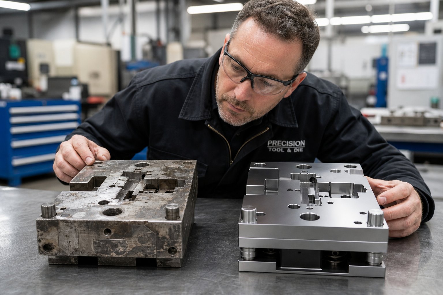
Replacing gut instinct with a structured die repair decision matrix removes emotion from a decision that directly affects cost, uptime, and part quality. The framework below gives tooling managers a repeatable process for evaluating die repair vs replacement cost at the component level.
Cost and Lead Time Factors in the Repair Decision
Two numbers drive the decision more than anything else: the cost of repair relative to replacement, and the time each option takes. A repair that costs 60% of a new component and only restores 50% of the expected service life is a poor investment. A replacement that costs less but takes eight weeks to arrive may not be viable when you're running production tomorrow.
Here's how to frame the comparison honestly:
- Repair cost - include labor, materials, heat treatment, any outsourced operations (EDM, coating), and the downtime while the die is on the bench.
- Replacement cost - include raw material, machining, heat treatment, fitting, and tryout time to qualify the new component in the die.
- Expected life after repair - each successive repair typically yields diminishing returns. A first weld repair might restore 80-90% of original life. A third repair on the same area rarely delivers more than 30-50%.
- Remaining program volume - if the part program has 100,000 pieces left, a repair that lasts 100,000 hits is perfectly adequate. If the program runs for another five years at 500,000 annual volume, a short-life repair just delays the inevitable replacement.
A practical threshold many experienced toolrooms use: when repair cost exceeds 50% of replacement cost and expected post-repair life is less than 60% of a new component's life, replacement is the better investment. Below that threshold, repair usually wins on both cost and turnaround time.
When Cumulative Damage Exceeds Repair Viability
Individual repairs can be perfectly sound. The problem is cumulative. Each weld adds residual stress. Each grind removes material and reduces the component's remaining shim range. Each thermal cycle subtly alters the metallurgy of the surrounding base material. At some point, you're no longer repairing the original component. You're maintaining a patchwork that bears little resemblance to the original design intent.
Watch for these signals that tell you when to replace stamping die components rather than repair them again:
- The component has been welded in the same area more than twice, and each repair lasts shorter than the previous one.
- Cumulative grinding has reduced the component below minimum height, and shim stacks are approaching their practical limit.
- Hardness testing reveals inconsistent zones across the working surface from multiple overlapping heat-affected areas.
- The component requires repair at increasing frequency, even though operating conditions haven't changed.
- Dimensional inspection shows the repaired geometry drifting further from nominal with each rework cycle.
That last point deserves emphasis. Tolerance degradation is progressive. Professional assessment guidelines suggest that if functionality cannot be restored to at least 80% of original specification after repair, replacement is the appropriate path. Repeated repairs that each leave the component slightly further from ideal create a compounding quality risk that eventually manifests as out-of-tolerance parts.
There's also a diagnostic signal hidden in repair frequency. If a component keeps failing despite sound repair execution, the root cause likely isn't wear or fatigue. It's a design problem: insufficient material, wrong steel grade, inadequate support, or operating loads beyond what the geometry can sustain. Repairing a design deficiency is like patching a tire with a nail still in it. You need die cut press rebuilding of that station with a redesigned component, not another repair of the existing one.
Design Features That Simplify the Replace Decision
The difficulty of the repair-or-replace decision depends heavily on how the die was built. Insert-style construction, where individual working components are held in pockets within a larger retainer, makes replacement straightforward. You pull the worn insert, drop in a pre-made spare, verify alignment, and return to production. The decision practically makes itself because replacement is fast and the spare inventory cost is manageable.
Solid-section die construction, where the working geometry is machined directly into a monolithic block, makes replacement far more expensive and time-consuming. Repairing becomes the default because replacing means re-machining an entire die section. This design choice, made years earlier during die engineering, directly shapes every future maintenance decision throughout the die's production life.
As die insert design principles illustrate, replaceable inserts reduce downtime because only the worn element changes rather than the full assembly. They also enable standardization: multiple stations using common insert geometries mean fewer unique spares to stock. The cost premium of insert construction at the build stage pays dividends across years of production through faster component swaps and cleaner repair-or-replace decisions.
The following die repair decision matrix consolidates these factors into a structured evaluation tool:
| Condition Severity | Repair Feasibility | Estimated Cost Ratio (Repair vs. Replacement) | Recommended Action |
|---|---|---|---|
| Minor edge wear or shallow chipping | High - standard grinding or light weld | 10-25% | Repair. Sharpen or weld and regrind. |
| Moderate crack or significant material loss | Moderate - requires skilled weld repair and heat treatment | 30-50% | Repair if first or second occurrence. Replace if third repair on same area. |
| Deep cracking, multiple previous repairs, or cumulative tolerance loss | Low - diminishing returns expected | 50-75% | Replace the component. Repair only as temporary bridge if lead time forces it. |
| Structural failure, base material degradation, or repeated systemic failure | Not viable - repair cannot restore function reliably | 75-100%+ | Replace immediately. Investigate root cause for possible redesign. |
| Any severity, but remaining program volume is under 10% of component life | Varies | Varies | Repair to finish the program. Do not invest in a new component for short remaining life. |
This matrix isn't a rigid rule. It's a starting point that forces the conversation to include all relevant variables rather than defaulting to the fastest or cheapest option in the moment. A disciplined approach to repair-or-replace decisions, applied consistently and tracked over time, reveals patterns that help you predict future failures and budget accordingly.
Whether you repair or replace, the component still needs to prove itself before full production resumes. A repaired die that hasn't been properly validated is just a hypothesis. Confirming it actually works, to tolerance, under real production conditions, requires its own structured process.
Post-Repair Validation and Quality Assurance
A repaired die component that measures correctly on the bench doesn't guarantee acceptable parts under production conditions. Press dynamics, material variation, and thermal effects during running all introduce variables that bench work alone can't simulate. Stamping die quality assurance after repair requires a structured validation sequence that progressively increases confidence, moving from static checks through controlled trials to monitored production before handing the die back to the floor.
Skip any step in this sequence and you risk discovering the problem at full speed, when scrap rates climb and the press goes down again. Here are the post repair die validation steps every toolroom should follow as a standard release protocol:
- Bench inspection - Dimensionally verify all repaired components against print specifications before reassembly. Confirm hardness, surface finish, and geometric tolerances on reworked surfaces.
- Reassembly and alignment check - Install the repaired components, verify proper seating, confirm shim heights, and check that all locating features engage without forced fit.
- Dry cycling - Run the die through several slow strokes without material to confirm mechanical clearance, timing, and free motion of all moving elements. Listen for interference, watch for binding.
- First-piece inspection - Run the first part at reduced speed. Measure all critical dimensions, check burr condition, inspect surface quality, and compare results against part tolerance specifications.
- Short production run with dimensional verification - Produce 20-50 consecutive parts at normal speed. Measure a sample set (typically 5-10 pieces) for dimensional stability across the run. Watch for drift, inconsistency, or progressive degradation.
- SPC monitoring during initial production - Release to full production with heightened measurement frequency for the first 500-1000 strokes. Plot key dimensions on control charts to verify the process is stable and centered, not just within tolerance.
- Full production release - Once initial monitoring confirms stable output, return to standard inspection intervals and document the release.
Bench Inspection and Dimensional Verification
Before the die ever goes back into the press, every repaired surface needs measurement against its original specification. This means micrometers or CMM readings on re-ground cutting edges, profile checks on re-machined form stations, and flatness verification on welded and re-surfaced faces. You're answering one question: did the repair restore the geometry to within working tolerance?
Pay particular attention to mating relationships. A punch that measures correctly in isolation can still produce bad parts if its relationship to the die opening has shifted. Check clearances between mating components, not just individual dimensions. For weld repairs, verify that alignment between guides, sections, and shimmed areas shows no forced fit, since weld distortion can alter component geometry in subtle ways that individual measurements miss.
Trial Run Protocols and First-Piece Qualification
The die trial run inspection protocol bridges the gap between bench confidence and production reality. Dry cycling catches mechanical interference, stripped threads, or assembly errors that would cause immediate damage. First-piece inspection catches dimensional problems before you've made a bin of scrap.
When you run that first piece, measure everything, not just the dimension you repaired. Repairs can shift adjacent features, alter strip progression timing, or change how material flows through form stations. A weld repair on a trim steel might be dimensionally perfect but introduce enough distortion to affect the next station's alignment. Checking only the repaired area misses these secondary effects.
During the short production run, you're looking for stability rather than just conformance. Five consecutive parts within tolerance is good. Five consecutive parts that trend steadily toward one tolerance boundary tells you the repair is already wearing or settling, and you may not get the expected life out of it. Die qualification processes used by tooling manufacturers follow this same principle: stamping trials confirm not just initial quality but functional stability under real production conditions.
Documentation and Tracking After Repair Completion
Validation without documentation is wasted intelligence. Every repair event, from the failure mode that triggered it through the validation results that released it, needs to feed into your die maintenance tracking system. The fields that matter for reconditioning a stamping die include:
- Date, hit count at failure, and hit count at return to production
- Failure mode and affected station or component
- Repair technique used (weld, grind, EDM, replacement)
- Heat treatment performed and hardness verification results
- Dimensional inspection results before and after repair
- First-piece and trial run measurements
- Technician performing the work and total repair hours
- Expected life of repair and next inspection trigger point
This record serves two purposes. Short-term, it provides traceable evidence that the die was validated before release, protecting you if quality questions arise later. Long-term, it builds the repair history that drives smarter decisions. Completed work orders should document what the repair was intended to accomplish and provide a means to track reoccurrences, turning isolated repairs into data points that reveal patterns. When you can see that a specific station has been repaired four times in twelve months, each time lasting fewer hits, you have objective evidence for the replacement decision discussed earlier.
SPC data collected during post-repair monitoring feeds this same system. If control charts show the process running stable and centered after repair, that's confirmation the technique worked. If they show drift or excessive variation from the start, the repair may be technically sound but functionally insufficient, and you've caught it before it becomes a customer quality issue.
A disciplined validation and documentation process transforms die repair from an isolated event into a data source that continuously improves your maintenance program. But here's the uncomfortable truth: some dies are simply harder to validate, harder to repair, and harder to keep running, not because of material choice or operator skill, but because of how they were designed in the first place.
How Die Design Choices Affect Long-Term Repairability
A die that fights you every time it comes to the bench wasn't built with repair in mind. Tight access, non-standard fasteners, monolithic construction where inserts should exist, and geometries that require full disassembly just to reach one worn component. These aren't random problems. They're design decisions made during engineering that echo through every future tool and die maintenance event for the life of the program.
Die design for maintainability isn't a secondary consideration bolted on after the forming geometry is finalized. It's a structural philosophy that determines whether a repair takes two hours or two days, whether you stock five spare components or fifty, and whether your technicians can swap a worn insert during a scheduled break or need to pull the entire die for a bench teardown.
Insert Construction and Modular Design for Easy Replacement
Modular die insert construction is the single most impactful design choice for long-term repairability. When cutting edges, form details, and wear-prone features are built as individual inserts held in pockets rather than machined directly into monolithic blocks, every downstream maintenance decision gets simpler.
Consider the difference in practice. A progressive die with solid-section trim steels requires pulling the entire lower die half to the surface grinder when edges wear. The same die built with sectional inserts allows a technician to pop out the worn piece, drop in a pre-ground spare, verify clearance, and return to production. The die never leaves the press for routine edge maintenance.
Design features that enable this modular approach include:
- Keyed insert pockets - precision-ground pockets with locating keys that guarantee rotational and positional alignment during reinstallation without tedious fitting.
- Accessible retention fasteners - socket head cap screws positioned where a wrench can reach them without removing adjacent components. Buried or obstructed fasteners add unnecessary disassembly steps.
- Guided strippers with independent mounting - strippers that lift off cleanly without disturbing other components, giving direct access to punches and die surfaces beneath.
- Wear plates on high-contact surfaces - sacrificial plates on heel blocks, guide rails, and blank holder faces that absorb sliding wear and can be replaced without reworking the parent structure.
- Doweled components with clearance relief - dowel pins for repeatable positioning combined with clearance slots that allow easy extraction without hammering or prying.
As the progressive die stamping principles outlined by precision tooling manufacturers confirm, high-wear sections like cutting edges are often designed as replaceable inserts from durable materials such as tungsten carbide, avoiding the need to fabricate an entirely new die block when edges wear. This modular philosophy directly lowers maintenance cost and minimizes production downtime.
Standardized Components That Reduce Spare Parts Complexity
Imagine stocking spare inserts for a 20-station progressive die where every cutting punch has a unique geometry, unique retention method, and unique shim configuration. Your spare parts inventory explodes, and your technicians spend time verifying which specific component fits which specific pocket. Standardization eliminates this complexity.
Smart die design uses common geometries across multiple stations wherever possible. Pilot punches share the same shank diameter and retention style. Pierce punches for similar hole sizes use identical head configurations that fit into standard ball-lock or shoulder-style retainers. Form inserts at symmetrical stations mirror each other, so one spare serves two locations.
Stamping die repairability features tied to standardization include:
- Common punch shank diameters and head styles - reducing the variety of retainers and backup configurations needed across the die.
- Standardized spring pockets and nitrogen cylinder bores - allowing interchangeable force components without custom machining during replacement.
- Uniform shim thicknesses and material grades - simplifying height compensation after grinding without searching for non-standard shim stock.
- Consistent fastener sizes throughout the die - a technician shouldn't need six different Allen keys to disassemble one tool. Two or three standard sizes covers everything when design enforces consistency.
Standardization also speeds up procurement. When your inserts use off-the-shelf blanks that any competent tool and die shop can finish-grind to profile, lead times drop from weeks to days. Custom one-off geometries with exotic retention schemes create single-source dependencies that leave you waiting when production is down.
How Engineering for Maintainability Reduces Lifetime Repair Cost
Every design feature listed above costs marginally more during the initial die build. Insert pockets require more machining than solid sections. Standardized components demand more upfront engineering coordination. Accessible fastener placement sometimes forces slightly larger die envelopes. But across a die's production life, spanning millions of hits and dozens of maintenance events, those upfront investments compound into dramatic cost savings.
Dies engineered with maintainability as a priority deliver:
- Faster component swaps that reduce press downtime per maintenance event
- Simpler alignment during reassembly that eliminates trial-and-error fitting
- More predictable wear patterns because replaceable elements are designed as sacrificial wear points
- Lower spare parts inventory cost through standardization
- Shorter technician training curves because consistent construction teaches patterns rather than exceptions
For teams building or expanding a die repair program, sourcing dies from manufacturers who explicitly design for repairability provides a structural advantage from day one. YICHEN, for example, pairs custom stamping die manufacturing with engineering attention to maintainability, durability, and stable production performance, delivering tooling that arrives production-ready with repair accessibility built into the design rather than treated as an afterthought.
The total cost of ownership calculation becomes clear over time. A die that costs 15% more to build but reduces every future repair event by 40% in time and complexity pays for that premium within the first year of production. Conversely, a die purchased on lowest initial price that requires heroic effort every time something wears ends up costing far more over its production life in labor, downtime, and frustration.
Design sets the ceiling on how efficient your maintenance program can ever become. But even the best-designed die still needs the right people, equipment, and systems to support it. For operations that currently send every repair out the door, bringing that capability in-house, even partially, opens up response times and cost structures that outsourcing alone can never match.
Building a Die Repair Program From Scratch
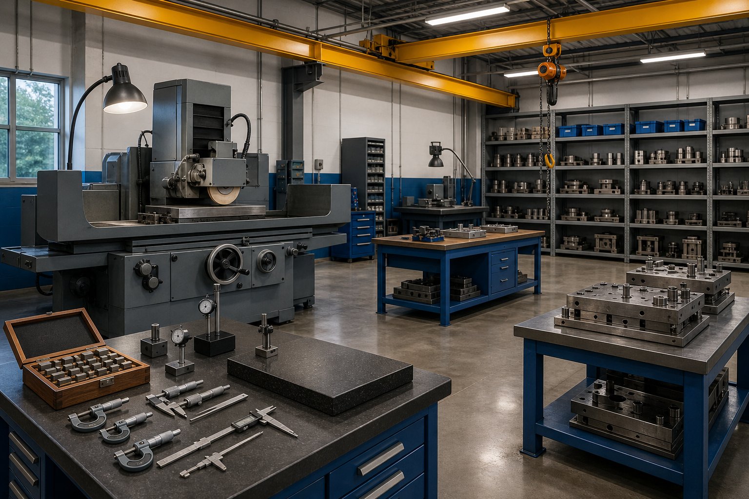
Outsourcing every repair to an external tool and die shop works until it doesn't. Transport time, vendor queues, communication gaps, and markup costs accumulate quietly until one day you realize you're spending more on turnaround delays than you would on a technician and a surface grinder. Building a die repair program setup in-house doesn't mean replicating a full-service tool and die shop overnight. It means establishing the internal capability to handle routine repairs quickly, while strategically outsourcing the major rebuilds that require specialized equipment or expertise you can't justify owning.
The hybrid model is where most stamping operations find their sweet spot. You handle sharpening, insert swaps, minor weld repairs, and component replacements internally. Wire EDM work, major weld rebuilds requiring vacuum heat treatment, and full station redesigns go to external partners with the capital equipment and metallurgical depth those jobs demand. The key is building the internal foundation that makes the routine work fast and the outsource decisions deliberate rather than default.
Toolroom Equipment and Staffing Essentials
What does a functional in-house toolroom actually need? Less than you might think for a starting point, and more than a workbench with a vise. The essential in-house toolroom equipment for die repair covers three categories: material removal, measurement, and assembly support.
Core equipment for a die repair program handling routine maintenance and minor repairs:
- Surface grinder (6x12 or 6x18 capacity) - handles the majority of sharpening work on punches, die sections, and inserts. This single machine addresses roughly 60% of all routine repair tasks.
- TIG or micro-TIG welding setup - for edge restoration, crack repair, and material buildup on worn components. Include a preheat oven or temperature-controlled blankets for proper thermal management of tool steels.
- Pedestal grinder and bench grinder - quick touch-ups, deburring, and preparation work that doesn't warrant tying up the surface grinder.
- Drill press and milling capability - even a small Bridgeport-style manual mill handles dowel hole work, pocket modifications, and bolt pattern corrections.
- Precision measurement instruments - micrometers, height gauges, dial indicators, gauge blocks, and a surface plate. Without measurement capability, you're guessing whether your repairs actually restored the geometry.
- Rockwell hardness tester - verifies that heat-treated components and weld repairs meet hardness specifications before going back into service.
- Die handling equipment - overhead crane or jib crane, die carts, and proper lifting hardware. Moving 2,000-pound die halves safely and efficiently requires infrastructure, not improvisation.
- Hand tools and assembly aids - torque wrenches, precision shims, parallel sets, v-blocks, clamps, and a comprehensive set of Allen keys and socket drives.
Initial investment for this baseline setup runs approximately $150,000-$300,000 depending on whether you buy new or source quality used equipment. The toolroom investment benchmarks from industry data suggest a roughly $500,000 outlay for a fully capable facility servicing 50 machine tools, with payback achievable within 12 months through doubled tool life and eliminated outsource markup. A smaller starting operation focused on routine repairs can begin at half that figure.
Staffing is where many programs stall. You need at least one experienced toolmaker or die maintenance technician who understands tool steels, can weld competently on hardened materials, operates a surface grinder confidently, and reads prints accurately. For operations running multiple press lines, two to three technicians per shift provides coverage for both reactive repairs and scheduled preventive maintenance. The staffing model scales with your die count and production intensity, but the minimum viable team is one skilled person with the right equipment and the authority to make repair decisions without waiting for multiple approvals.
Training pathways for less experienced staff typically follow a progression: start with die cleaning and inspection, advance to sharpening and component replacement, then build toward welding and complex bench repairs under supervision. Apprenticeship-style learning paired with manufacturer training courses on specific equipment accelerates development, but expect 18-24 months before a new technician handles major repairs independently.
Spare Parts Strategy and Inventory Management
An in-house repair capability without a die repair spare parts inventory is a technician staring at an empty shelf while production waits. The inventory strategy doesn't need to be complicated, but it needs to be intentional.
Start by identifying your consumption patterns. Which components wear most frequently? Which ones have the longest replacement lead times? Which failures cause the most downtime when a spare isn't available? Those three questions define your stocking priorities.
A practical approach to spare parts inventory management:
- High-wear, short-lead items - keep multiples on the shelf. Pierce punches, pilots, standard die buttons, and springs fall here. These are inexpensive relative to the downtime they prevent.
- Medium-wear, moderate-lead items - stock at least one spare. Form inserts, trim steels, specialty punches, and guide bushings. One spare means you can swap immediately and repair the worn piece at your own pace rather than under emergency pressure.
- Low-wear, long-lead items - don't necessarily stock, but have sourcing arrangements in place. Die shoes, large cavity sections, and custom castings. Know your vendor, know the lead time, and build that information into your replacement decision framework.
- Consumables - grinding wheels, welding filler rods (matched to your specific tool steels), shim stock in standard thicknesses, dowel pins, socket head cap screws in your standard sizes, and nitrogen cylinder seals. Running out of a $15 consumable shouldn't ever be the reason a $200,000 press sits idle.
Standardized die construction pays dividends here. When multiple dies share common punch sizes, insert geometries, and retention hardware, your inventory covers more tools with fewer unique part numbers. This is one reason why sourcing dies from manufacturers like YICHEN, who prioritize maintainability in their designs, gives repair programs a structural advantage from day one. Dies that arrive with standardized, accessible components reduce the spare parts complexity your program must manage from the outset.
Track consumption against hit counts. If a specific punch averages 150,000 hits before needing replacement, and you run 50,000 hits per week on that die, you know to have a spare ready every three weeks. This predictive approach eliminates the reactive scramble of discovering you need a component after it's already failed.
Documentation Systems and Continuous Improvement
Here's where most internal repair programs either mature into something powerful or stagnate into a cycle of repeated mistakes. The difference comes down to one thing: whether you document what you do and use that documentation to get better.
Documentation quality determines whether a die repair program improves over time or repeats the same mistakes indefinitely.
A stamping die maintenance documentation system doesn't need to be expensive software. It needs to capture the right information consistently. At minimum, every repair event should record the failure mode, the station and component affected, the repair technique used, the hit count at failure, the validation results, and the technician who performed the work. This is the same set of fields described in post-repair validation, but now organized as a living database rather than a one-time checklist.
The real power of documentation emerges over time. When your system shows that Station 4's form insert has been repaired five times in eighteen months, each time for the same galling failure, you have evidence for a material upgrade or coating change rather than another repair. When data reveals that welds performed by one technician consistently outlast those done by another, you have a targeted training opportunity. When hit-count-to-failure data shows a consistent pattern across similar dies, you can schedule preventive replacements before failures occur.
This is what transforms reactive repair into data-driven maintenance scheduling. As experienced die shop management consultants emphasize, work order systems that document what each repair was intended to accomplish and track reoccurrences create a feedback loop that continuously improves both repair quality and scheduling accuracy. Data from previous work orders feeds improved preventative maintenance plans and reveals whether previous repairs resulted in unintended consequences.
Implementation options range from simple spreadsheet tracking (adequate for small operations with fewer than ten active dies) to full CMMS platforms like MaintainX or UpKeep that offer barcode scanning, mobile access, and automated scheduling triggers. Choose the level of sophistication your team will actually use consistently. A simple system used diligently outperforms a complex system used sporadically.
The continuous improvement cycle looks like this: repair the die, document the event, validate the repair, monitor performance, analyze patterns across events, adjust procedures or schedules based on findings, and feed lessons back into training. Each cycle makes your program slightly more predictive and slightly less reactive. Over twelve to eighteen months, a disciplined operation shifts from fighting fires to preventing them, and the production floor notices the difference in uptime, part quality consistency, and fewer emergency calls to the toolroom.
Building internal repair capability isn't about eliminating external vendors entirely. It's about controlling the work that benefits most from speed and familiarity while leveraging external expertise for the work that genuinely requires it. The hybrid model, supported by trained people, the right equipment, a smart spare parts strategy, and documentation that actually drives decisions, creates a repair program that compounds in value every month it operates.
Frequently Asked Questions About Metal Stamping Tool and Die Repair
1. What is the difference between die maintenance and die repair?
Die maintenance is preventive and scheduled, preserving a die in its current working state through tasks like sharpening, lubrication, and inspection. Die repair is corrective, restoring a die that has already failed or degraded beyond acceptable production tolerances. Maintenance aims to prevent failure; repair responds after failure occurs. Separating these two cost categories in your tracking system is essential for accurate budgeting and identifying whether your tooling program needs better prevention or better restoration procedures.
2. How do you diagnose what caused a stamping die to fail?
Start by examining the parts coming off the press. Burrs indicate worn cutting edges, dimensional drift points to worn form stations or loose components, and surface scratches suggest galling. Then trace the defect back to the responsible die station using your strip layout. Inspect that station for the corresponding condition: edge wear, material buildup, cracking, or misalignment. This three-step framework, observe the part defect, identify the station, inspect the die condition, eliminates guesswork and targets your repair effort precisely where it is needed.
3. Why is heat treatment important after welding a stamping die?
Welding tool steels without proper pre-heat and post-weld heat treatment creates brittle martensite in the heat-affected zone. This brittle microstructure has almost zero tolerance for cyclic stress and will crack within thousands of press strokes, often causing more damage than the original failure. Pre-heating reduces thermal gradients during welding, while post-weld tempering transforms brittle structures into tempered martensite that retains hardness with improved toughness. Skipping these thermal steps is the single most common cause of weld repair failure in die components.
4. When should you replace a die component instead of repairing it?
Replace rather than repair when the component has been welded in the same area more than twice with diminishing life each time, when cumulative grinding has reduced it below minimum height, when hardness testing shows inconsistent zones from overlapping heat-affected areas, or when repair cost exceeds 50% of replacement cost while expected post-repair life falls below 60% of a new component. Also consider replacement when repeated failures point to a design deficiency rather than normal wear, since repairing a design problem only delays the inevitable.
5. What equipment is needed to start an in-house die repair program?
A functional starting toolroom needs a surface grinder for sharpening work, a TIG or micro-TIG welding setup with preheat capability for crack and edge repairs, precision measurement instruments including micrometers and a surface plate, a Rockwell hardness tester for verifying repairs, die handling equipment like an overhead crane, and basic machining capability such as a drill press or manual mill. Initial investment ranges from $150,000 to $300,000 depending on new versus used equipment. Partnering with die manufacturers like YICHEN who design for maintainability gives your program an advantage, as dies arrive with standardized, accessible components that simplify both repairs and spare parts management.


