


What Die Stamping Support Means for Large Parts
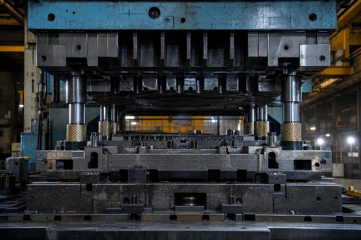
When you hear "die stamping," you might picture a compact press punching out brackets or clips. Scale that up to structural panels, full-width chassis rails, or industrial enclosures, and the engineering picture changes dramatically. Die stamping support for large parts is not a single component. It is an entire infrastructure system working together to keep oversized tooling rigid, aligned, and precise under extreme loads.
Defining Die Support Infrastructure for Large-Format Stampings
Die stamping support for large parts refers to the integrated system of bolster plates, sub-bolsters, die shoes, guide systems, and press bed configurations engineered to maintain structural rigidity and dimensional precision across oversized tool footprints.
Each element in this large format die support infrastructure carries a specific job. Bolster plates provide the stable foundation, distributing press loads evenly across the bed. Sub-bolster grids add localized stiffness where force concentrations peak. Die shoes hold punches, forming steels, and die buttons in alignment, and their thickness directly governs deflection resistance. Guide pins and bushings keep upper and lower halves tracking true across every stroke. Together, the bolster plate configuration for oversized dies and die shoe rigidity for large stampings determine whether a tool produces consistent parts or drifts out of tolerance within the first hundred hits.
Why Conventional Die Support Falls Short at Scale
Here is the mistake that catches many shops off guard: treating a large part tool like a scaled-up version of a small one. A compact die set can rely on standard shoe thicknesses and off-the-shelf guide components because deflection forces remain manageable. Stretch that same design philosophy across a footprint two or three times wider, and you encounter non-linear challenges in bending moment, thermal expansion, and force distribution that no simple multiplier can predict. Deflection does not double when the span doubles; it increases at a far steeper rate. Thermal gradients span greater distances, creating differential expansion that shifts alignment mid-run. Force distribution grows uneven, concentrating stress where support is thinnest.
These realities mean large-format tooling demands purpose-built support strategies from the ground up. The question becomes: exactly how do those engineering variables compound as part size grows?
Why Large Parts Demand Specialized Support Engineering
Imagine doubling the footprint of a die set. You might expect the support requirements to double as well. In reality, the structural demands grow at a rate that outpaces the size increase itself. This non-linear relationship between part dimensions and support needs is exactly where die support engineering challenges at scale become apparent, and where conventional assumptions break down.
Non-Linear Scaling of Structural Demands
Consider a simple beam analogy. When you double the unsupported span of a beam under uniform load, deflection does not merely double. It increases by a factor of sixteen for a simply supported condition, because deflection scales with the fourth power of span length. Die shoes and bolster plates behave similarly. Non-linear deflection in large die sets means a modest increase in tool width can produce a disproportionate jump in mid-span sag, concentrating stress in areas the original design never anticipated.
Thermal behavior follows the same pattern. A compact die might experience uniform temperature across its working surface during a production run. Stretch that surface to 1,500 mm or beyond, and thermal gradients develop across the tool face. Thermal expansion management for oversized dies becomes critical because differential growth of just a few hundredths of a millimeter across the span shifts punch-to-die clearances unevenly, degrading part quality and accelerating wear on one side of the tool.
Force distribution in large format stamping compounds both problems. Stamping forces rarely land perfectly centered. Off-center loads that a compact die absorbs with minimal tilt create significant angular deflection on a wide-span tool, generating uneven material flow and inconsistent part geometry.
Interconnected System Challenges at Large Scale
Large-format die support is not just a tooling problem. It is a full-system problem. The press frame, bolster, die set, blank holder, and part extraction mechanism all interact. A stiff die shoe mounted on a flexible bolster still deflects. A rigid bolster inside a press frame that lacks torsional stiffness still allows misalignment under off-center loads. Every link in the chain matters.
The key engineering variables that scale non-linearly with part size include:
- Deflection moment: increases with the square to fourth power of unsupported span, depending on support conditions
- Thermal gradient span: longer distances amplify differential expansion and create mid-tool alignment drift
- Alignment tolerance accumulation: more guide points across a wider footprint compound individual positional errors
- Cushion pressure uniformity: larger blank holder faces make it harder to maintain even force distribution across the draw area
Engineers familiar with compact tooling often apply rules of thumb for shoe thickness ratios, guide pin spacing, or cushion pressure settings. Those guidelines were developed for tools where span lengths keep deflection manageable and thermal gradients negligible. Scaling them up without recalculating for non-linear effects leads to premature wear, tolerance drift, and inconsistent parts. The physics simply will not cooperate.
This system-level complexity raises a practical question: what does the press itself need to deliver in order to keep all these interconnected variables under control?
Press Infrastructure and Tonnage for Large Part Production
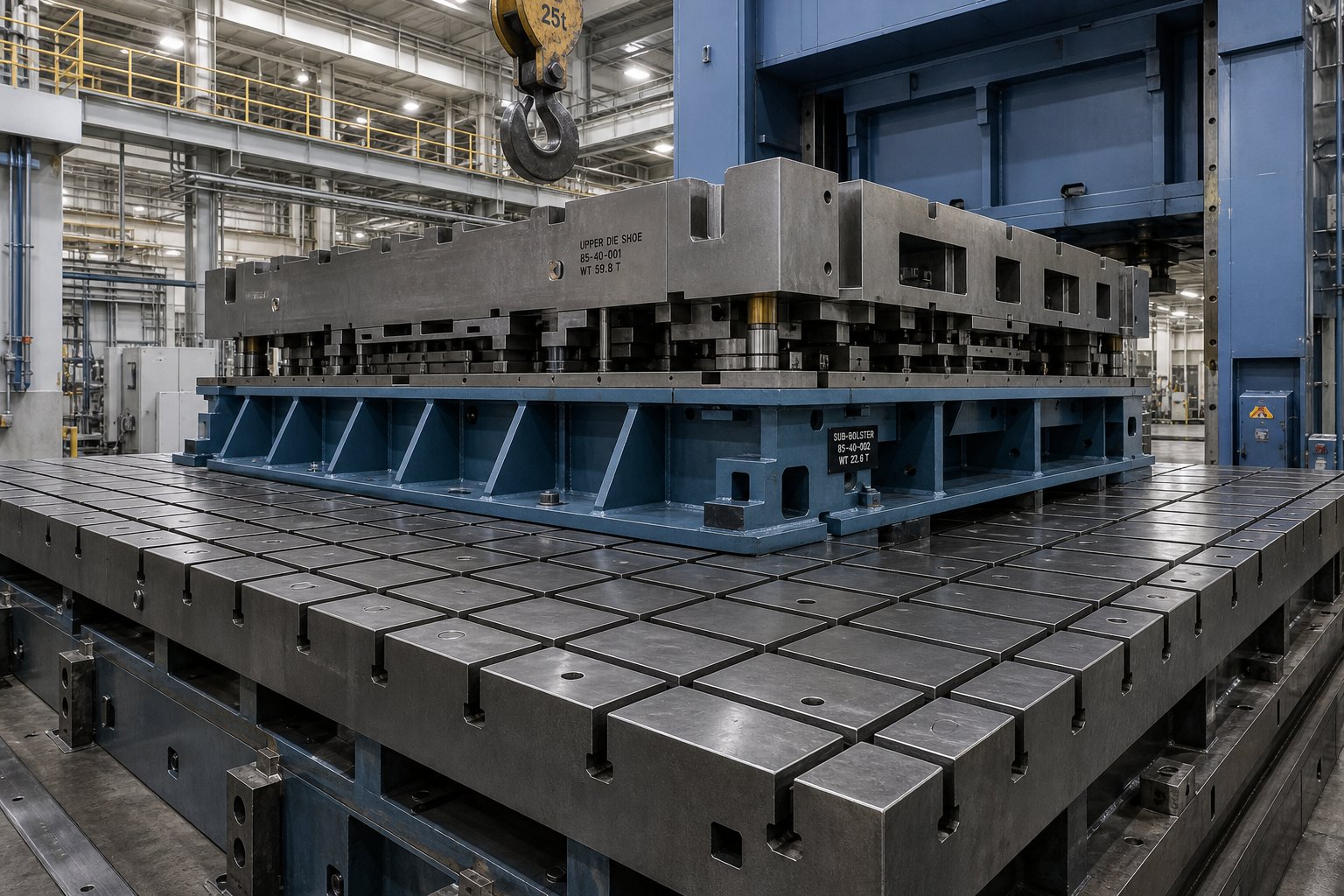
The press is not just the machine that delivers force. For large-format stamping, it becomes the structural backbone of the entire support system. Selecting a press based solely on tonnage capacity is a common and costly oversimplification. Press bed size selection for large parts requires evaluating bed area, stroke length, daylight opening, and how force distributes across the full die footprint, all as interdependent variables rather than isolated specifications.
Press Bed Size and Daylight Opening Requirements
A large part needs room to exist within the press, and that sounds obvious until you realize how many constraints stack up. The bed must accommodate the full die set footprint with enough margin for bolster clamping, feed mechanisms, and scrap evacuation. Daylight opening requirements for large die sets go beyond simply fitting the tool height. You need clearance for die loading, part extraction, and any automation gripper travel between upper and lower tools.
Stroke length introduces another trade-off. A longer stroke accommodates deeper draws, which large structural panels and enclosures often demand. However, as The Fabricator explains, for constant torque capacity, the shorter the total press stroke, the higher the available tonnage curve. In other words, a press with generous daylight for deep large-part draws delivers less usable force at points above bottom dead center. Engineers selecting presses for large parts must balance draw depth against the tonnage actually available where forming begins.
Tonnage Capacity and Force Distribution Across Large Footprints
Press tonnage requirements for large stampings cannot be estimated by multiplying part area by a generic pressure value. The actual tonnage demand depends on material strength, thickness, part geometry complexity, and features like draw beads or stake beads added for springback control. With today's advanced high-strength steels reaching tensile strengths of 980 MPa or higher, AHSS Insights notes that traditional rule-of-thumb calculations often underpredict the required tonnage, making FEA-based prediction essential for large-format applications.
Force distribution across the bed matters as much as total capacity. A press tonnage capacity is typically rated for centered loads using at least 66% of the bed length. When a large die concentrates forces in a smaller zone or applies load off-center, the effective capacity must be derated. For large parts that are rarely symmetric, this off-center bias grows more pronounced, especially in transfer press setups where draw stations and trim stations produce drastically different loads at opposite ends of the bed.
| Parameter | Structural Panels | Chassis Components | Large Enclosures |
|---|---|---|---|
| Typical Bed Dimensions | 3,000-5,000 mm x 2,000-2,500 mm | 2,500-4,000 mm x 1,500-2,000 mm | 2,500-4,500 mm x 2,000-3,000 mm |
| Tonnage Range | 1,600-5,000 tons | 800-2,500 tons | 1,000-3,000 tons |
| Stroke Length | 600-1,200 mm | 400-800 mm | 500-1,000 mm |
| Daylight Opening | 1,500-2,500 mm | 1,200-1,800 mm | 1,400-2,200 mm |
| Typical Material Thickness | 0.6-2.0 mm | 1.5-6.0 mm | 1.0-3.0 mm |
| Primary Force Challenge | Large area, moderate unit pressure | High strength, concentrated loads | Deep draws, off-center loads |
Bolster Plate and Sub-Bolster Configurations
The bolster plate is the interface between press bed and die shoe, and for large parts it becomes a critical structural element in its own right. Bolster plate thickness for oversized dies must resist localized bending between bed support points. A thin bolster spanning a wide press bed sags under concentrated die loads, transferring that deflection directly into the tool and the finished part.
Sub-bolster grid pattern engineering addresses this by adding an intermediate support layer between the main bolster and the die shoe. These grid structures, typically machined steel plates with rib patterns or T-slot configurations, redistribute point loads into broader zones. The grid spacing is calculated based on expected force concentrations. Areas under draw punches or heavy forming stations receive tighter grid spacing, while regions supporting lighter operations like piercing can use wider intervals.
Think of it this way: the bolster and sub-bolster system acts like a foundation under a building. A single slab works fine for a small structure, but a large building needs piles, grade beams, and reinforced footings distributed according to where the heaviest loads land. The same principle applies here. Without purpose-engineered sub-bolster configurations, localized deflection under the die creates uneven clearances, accelerates tool wear in concentrated zones, and introduces part-to-part dimensional variation that grows worse over a production run.
The relationship between part size, material grade, and press infrastructure is multiplicative rather than additive. A larger part in a higher-strength steel does not just need a bigger press. It needs a stiffer bolster, a more distributed sub-bolster grid, wider force monitoring coverage, and more precise off-center load management. These infrastructure decisions lock in before the die is ever designed, which is why the die set itself must be engineered with these press-level constraints as fixed inputs.
Die Set Construction and Deflection Management
Press infrastructure defines what the die set has to work within. The die itself, though, is where precision lives or dies. For large-format tooling, die set construction involves engineering choices that simply do not exist in compact tools. Wider spans, heavier sections, and greater thermal mass all demand structural strategies that go well beyond thickening a die shoe and adding a few extra guide pins.
Segmented Die Construction for Oversized Tools
Building a large die as a single monolithic block creates problems on multiple fronts. Machining a one-piece die insert spanning 2,000 mm or more pushes the limits of available CNC equipment, complicates heat treatment, and makes field repairs impractical. That is why segmented die construction for large parts has become the standard approach for oversized tooling.
Segmented inserts break the die face into manageable sections, each individually machined, heat-treated, and fitted into the die shoe. This modular strategy offers three practical advantages. First, manufacturability improves because each segment fits within standard machine tool envelopes. Second, maintenance access becomes targeted. A worn or damaged section can be removed, reground, or replaced without pulling the entire die from the press. Third, and critically for large tools, segmentation accommodates thermal expansion. During production, the die face heats unevenly. A monolithic insert fights that expansion internally, building stress that can crack hardened tool steels. Segmented inserts allow controlled gaps between sections that absorb differential growth without distorting the working surfaces.
The trade-off is precision at segment boundaries. Each joint between inserts must be shimmed and aligned to maintain a continuous forming surface. Misalignment at these interfaces shows up immediately as witness lines on finished parts or localized thinning in drawn panels.
Guidance Systems and Alignment at Scale
Keeping upper and lower die halves tracking true across a wide footprint is a fundamentally different challenge than guiding a compact tool. Guide pin placement for oversized die sets must account for longer unsupported spans, greater thermal movement, and higher cumulative side loads during forming.
As Metal Forming Magazine explains, the guide bushing should engage the guide post at the working level of the die whenever possible. This loads the post in shear, its strongest condition, and minimizes bending moment that causes deflection-induced misalignment. In large die sets, placing bushings high above the work surface out of convenience amplifies this bending effect across the wider tool span, making precise engagement height even more critical.
For large-format tooling, guide pin length should be kept to the minimum that satisfies engagement and bypass requirements. Longer posts deflect more under side load, and when those posts span a die set measuring several meters across, even small angular errors at the guide translate into meaningful positional drift at the far edges of the tool. Ball-bearing guide components provide zero running clearance through preload, but they carry a risk in large dies that generate heavy lateral thrust. Side loads transfer to individual ball bearings in point contact, which can dig tracking marks into the post or bushing surfaces over time.
Heel block design for large format tooling addresses what guide pins alone cannot handle. Dies producing unbalanced forming loads or heavy side thrust typically use boxed-heel construction either in place of or alongside guide posts. In large tools, the relationship between heel blocks and guide pins matters more. Some engineers prefer guide pins to engage first, providing initial alignment, with heel plates absorbing lateral forces during the working stroke. For this approach to function, the running clearance between heel plate surfaces must be less than the guide pin clearance. Otherwise, the pins deflect under load before the heel plates can pick up the thrust.
Preventing Structural Deflection in Large Die Sets
Die shoe rigidity is the last line of defense against deflection. For compact tools, standard shoe thickness ratios work well because the unsupported span stays short. Stretch that span to large-format dimensions and the shoe must grow disproportionately thicker, often incorporating die shoe ribbing for deflection control on the underside to add stiffness without proportional weight increase.
Ribbed die shoes use machined or cast reinforcement patterns, typically running perpendicular to the longest unsupported span, that increase the section modulus of the shoe without making it solid steel throughout. This keeps die weight within crane handling limits while delivering the rigidity that a solid shoe of equivalent stiffness would require. The rib pattern is engineered around expected load locations. Areas beneath heavy forming stations receive closer rib spacing, while lighter-duty zones use wider intervals.
When die support falls short, the failures are predictable and progressive. Inadequate structural support in large die sets produces a cascade of problems:
- Tolerance drift across the part as mid-span deflection shifts punch-to-die clearances unevenly
- Uneven wear patterns concentrated where deflection creates tighter-than-designed clearances
- Premature punch failure from angular loading caused by shoe flex under off-center forces
- Inconsistent material flow as the die face distorts under load, altering draw bead engagement
- Part springback variation from stroke to stroke as thermal and mechanical deflection fluctuate during a production run
Each of these failure modes feeds the others. Uneven wear changes clearances, which worsens material flow, which shifts forming forces, which accelerates deflection in new areas. What starts as a subtle dimensional drift becomes a compounding quality problem that shortens die life and drives up scrap rates.
Managing these interconnected deflection risks through shoe design, guide systems, and segmented construction sets the structural stage. The next variable that determines whether a large die actually produces good parts is how force reaches the blank itself, specifically how cushion systems distribute pressure across an extended die face.
Die Cushion and Blank Holder Systems at Scale
Structural rigidity keeps the die aligned, but it is the cushion system that determines whether the blank behaves during forming. In compact tooling, a bank of nitrogen cylinders or a single-zone press cushion handles blank holder force without much fuss. Scale that die face to large-format dimensions, and blank holder force distribution for large parts becomes a primary engineering challenge rather than a secondary setup detail. Uneven pressure across an extended die face does not produce a slightly imperfect part. It produces wrinkles on one side and tears on the other.
Hydraulic vs Nitrogen Die Cushion Performance at Scale
Why does die cushion type matter more as parts get bigger? Consider what happens physically. A nitrogen cylinder array delivers force based on gas pressure, and that pressure rises progressively as the cylinder compresses during the stroke. Art Hedrick at The Fabricator notes that stand-alone gas spring pressure can double during the downstroke, a characteristic that complicates force control in any application but becomes especially problematic across a wide blank holder face. With dozens of nitrogen cylinders spanning a large die, minor differences in gas charge, seal friction, or thermal state between individual units create pressure variation from zone to zone.
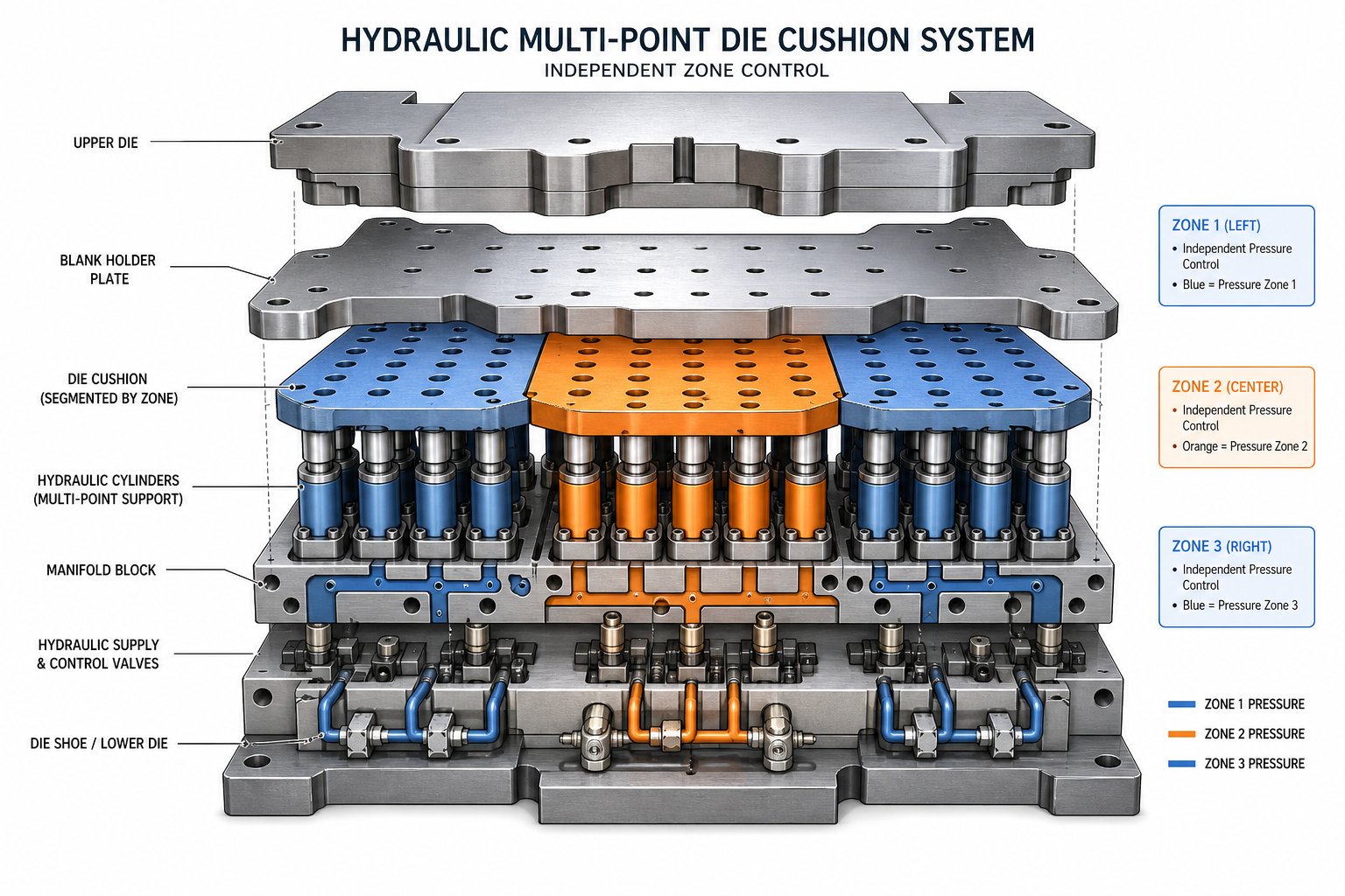
Hydraulic die cushion systems for large format stamping address this differently. A pump-controlled hydraulic cushion uses fluid pressure regulated by servo or proportional valves, delivering programmable force profiles that can remain constant, ramp up, or taper down throughout the stroke. Research into pump-controlled hydraulic die cushion pressure control demonstrates that advanced control strategies can achieve pressure overshoot as low as 6.5% with build-up times under 0.4 seconds, giving engineers the dynamic precision large-format applications demand. Pneumatic cushions, while simpler and less expensive, suffer from air compressibility that limits both force precision and response speed, generally restricting them to lighter-duty operations where the blank holder footprint stays manageable.
| Cushion Type | Force Uniformity | Response Time | Adjustability | Large Format Suitability |
|---|---|---|---|---|
| Nitrogen Cylinder Arrays | Moderate; varies with stroke depth and individual cylinder condition | Fast initial response; no active control during stroke | Limited to initial charge pressure and cylinder selection | Suitable for moderate footprints; zone-to-zone variation grows with array size |
| Hydraulic Multi-Point | High; servo-controlled pressure regulation per zone | Good; programmable profiles with sub-second build-up | Fully programmable force curves; independent zone control | Preferred for large-format; enables multi-zone differential pressure |
| Pneumatic | Low; air compressibility creates pressure lag and variation | Moderate; limited by air volume and valve response | Basic pressure adjustment; no dynamic profiling | Generally unsuitable for large-format draws; acceptable for light blanking |
Blank Holder Force Mapping Across Extended Die Faces
Imagine a blank holder face spanning 3,000 mm across a large structural panel die. The material does not flow uniformly into the die cavity. Corners resist flow differently than straight edges. Deep-draw regions pull metal faster than shallow flanges. If the blank holder applies the same pressure everywhere, some zones starve for material and tear, while others feed too freely and wrinkle. This is precisely why multi-zone cushion control for oversized dies exists.
Multi-point hydraulic cushion systems divide the die face into independently controlled pressure zones, each fed by its own cylinder or cylinder group. An operator can apply higher retention force near shallow flanges where wrinkling risk peaks and reduce force near deep-draw pockets where tearing is the concern. This zone-by-zone mapping of blank holder force replaces the old approach of finding a single compromise pressure and hoping it works everywhere.
Lifters and pressure pads follow the same logic of distribution. In a compact die, a few evenly spaced lifter pins adequately support the blank during extraction and provide initial hold-down. In a large draw die, those lifters must be positioned according to the part geometry and material flow pattern, not just spaced on a grid. Areas prone to localized thinning, typically corners of deep draws and transitions between formed and unformed zones, need dedicated pressure pad support to maintain contact and prevent the blank from lifting prematurely during the stroke.
The nitrogen vs hydraulic die cushion decision for large tooling ultimately comes down to control resolution. Nitrogen systems work well where force requirements are relatively uniform and the footprint stays within bounds where cylinder-to-cylinder variation remains tolerable. When part geometry creates differential flow demands across an extended face, hydraulic multi-point control provides the adjustability to tune each zone independently, turning what would otherwise be a compromise into an engineered solution.
Cushion system selection locks in how force reaches the blank, but it does not answer a broader question about die configuration: should these large parts run through a progressive die with integrated stations, or does their size push the decision toward a transfer system with discrete tooling at each stage?
Progressive vs Transfer Die Selection for Large Parts
The die configuration question is not abstract. It determines how material enters the tool, how parts move between operations, and what kind of support infrastructure each station requires. For compact components, progressive dies dominate on speed and cost-per-part. But as part envelopes grow, the physics of strip feeding and carrier integrity shift the calculus. Understanding where progressive dies hit their practical ceiling and where transfer systems take over is central to any large-format tooling decision.
When Progressive Dies Reach Their Size Limit
Progressive dies rely on a continuous metal strip feeding through sequential stations, with the part remaining attached to a carrier web until the final cutoff. This works beautifully for small to medium components. The strip stays rigid enough to advance accurately, pilot holes maintain registration, and the carrier web absorbs inter-station forces without distortion.
Scale that up, and problems emerge fast. The maximum part size for progressive die stamping is constrained by strip width, coil availability, and the carrier web's ability to support increasingly heavy partially-formed features between stations. As Fictiv notes, progressive stamping keeps the part attached to the carrier strip throughout the process, meaning any part large enough to compromise strip rigidity threatens the entire progression's accuracy. Wider strips demand greater feed precision, heavier pilot forces, and more robust feed equipment. Beyond roughly 600-800 mm in strip width, the practical challenges of maintaining progression accuracy, managing strip camber, and preventing inter-station sag become prohibitive for most applications.
Strip waste compounds the economic problem. A large part on a progressive strip requires a carrier web on both sides plus inter-part spacing, and the percentage of material that becomes scrap grows disproportionately as part size increases. What works at 85% material utilization for a small bracket may drop to 60% or less for a large panel, eroding the cost advantage that justified progressive tooling in the first place.
Transfer Die Advantages for Large Discrete Parts
Transfer die systems solve the carrier strip problem by separating the blank from the coil at the first station and mechanically transporting it between subsequent operations. Larson Tool highlights that transfer dies move the workpiece independently between stations, allowing each station to operate on a free part that can be repositioned and manipulated at various angles. This independence is what makes transfer die support for oversized stampings practical where progressive approaches fail.
For large parts, the transfer approach delivers several structural advantages. Each die station can be purpose-built for its specific operation without the constraint of matching a common strip pitch. Station spacing can accommodate the full part envelope plus clearance for gripper fingers or walking beams. And because each blank is discrete, material utilization improves significantly since there is no carrier web consuming material on every cycle. Standard Die International points out that the elimination of the connection web used to carry parts through a progressive process saves material on each piece, reducing overall piece price.
The trade-off is speed and inter-station support complexity. Transfer systems run slower than progressive dies, typically operating at 8-25 strokes per minute for large parts versus the 200-600+ strokes per minute achievable with progressive tooling on small components. Each transfer station needs its own die support system, including independent bolster configurations, guide systems, and sometimes individual cushion setups, all aligned across the full transfer line to sub-millimeter accuracy.
| Criteria | Progressive Die | Transfer Die |
|---|---|---|
| Maximum Part Envelope | Limited by strip width (typically under 600-800 mm) | Limited only by press bed size (2,000 mm+ feasible) |
| Strip/Material Waste | Higher for large parts due to carrier web and spacing | Lower; discrete blanks eliminate carrier web waste |
| Die Support Complexity | Single die set; integrated stations share one shoe and bolster | Multiple independent stations; each requires dedicated support infrastructure |
| Station-to-Station Accuracy | Inherent; strip pilots maintain registration across all stations | Dependent on transfer mechanism precision and inter-station alignment |
| Production Rate | Very high (200-600+ SPM for small parts) | Moderate (8-25 SPM for large parts) |
| Part Manipulation Between Stations | None; part stays in plane on strip | Full repositioning possible; allows complex forming sequences |
Hybrid Approaches for Automotive Structural Components
Automotive structural panel die selection rarely falls cleanly into one category. A vehicle body side outer, a full-width dash panel, or a structural floor pan clearly demands transfer systems due to sheer size. But within the same vehicle platform, dozens of brackets, reinforcements, and mounting plates attach to those large panels. These smaller components often run on progressive dies at high volume and low unit cost, even though they ultimately become part of a large assembly.
The hybrid reality looks like this: transfer presses handle the large structural shells and rails where part size makes progressive tooling impractical, while progressive dies stamp the smaller repeating brackets and clips that bolt or weld onto those structures. Some tier-one automotive suppliers run both systems in the same facility, feeding progressive-stamped sub-components directly into assembly cells alongside transfer-pressed panels.
For chassis brackets and structural reinforcements that fall in the mid-size range, the decision often hinges on annual volume and geometric complexity rather than size alone. A bracket that exceeds comfortable progressive strip width but does not justify a full multi-station transfer line may use a compound die or a two-station tandem press setup as a practical middle ground.
Regardless of which configuration wins the selection decision, one constant remains: the material itself imposes its own rules. How high-strength steels spring back across a large panel, how aluminum flows over an extended draw face, and how tolerances stack up across wide die footprints all shape the final part quality in ways that no amount of structural support can compensate for without deliberate material flow engineering.
Material Flow and Tolerance Control Across Large Die Faces
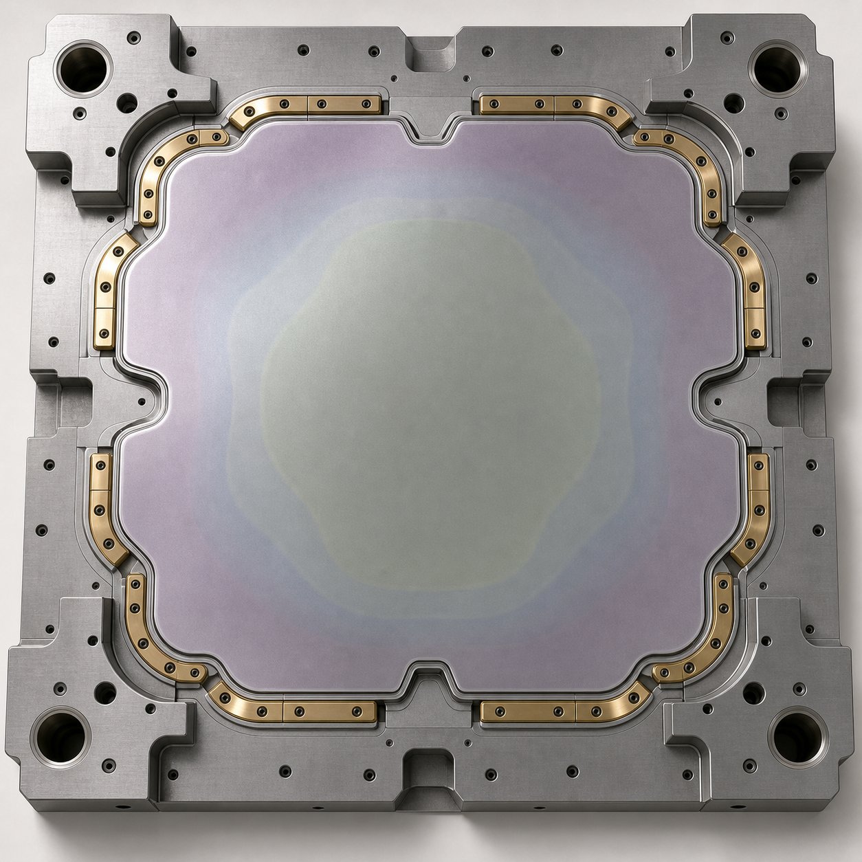
Structural rigidity and cushion control set the stage, but the material itself is the final variable that determines whether a large stamped part meets print. Different alloys respond to forming forces in fundamentally different ways, and those responses amplify as part size grows. A springback angle that barely registers on a 200 mm flange can push a 1,500 mm panel several millimeters out of spec. Material flow control across extended die faces is not an afterthought. It is what separates a functional large-format tool from an expensive paperweight.
High-Strength Steel Springback Challenges in Large Panels
Springback management in large format stamping starts with a blunt reality: experience-based compensation methods developed for mild steel do not transfer to advanced high-strength grades. As MetalForming Magazine puts it, "compensation is not commensurate with experience" when working with newer high-strength steels, because prior material history simply does not exist for these grades. The familiar rules break down.
Springback, sidewall curl, and panel twist all originate from unbalanced residual stresses in the formed part. In large panels, those stresses act across greater distances, turning a small angular error per unit length into a large cumulative deviation at the panel edges. A hat-section channel formed in dual-phase 980 steel might curl several degrees in the sidewall on a compact part. Stretch that same geometry across a full-width structural rail, and the curl compounds into a twist visible to the naked eye.
Research into springback simulation has exposed specific weaknesses when higher-strength steels are involved. Prediction accuracy is highly sensitive to anisotropy values, work-hardening rules, friction coefficients, and strain-rate sensitivity models. Each of these variables interacts differently across a large tool face where conditions are not uniform. The friction at the draw radius on one side of a panel differs from the other side due to lubricant migration, temperature variation, and local tool surface condition. On a compact die, these local differences average out. On a large die, they produce asymmetric springback that no single compensation value can correct.
Addressing springback in large HSS panels demands intervention at the product design stage rather than relying solely on die compensation. Practical strategies include avoiding sharp wall angles that trap elastic stress, using open-end sections instead of closed channels where possible, and incorporating stiffening features like darts or step flanges that lock geometry in place. When draw forming is the only practical method, post-stretching the sidewalls by locking out the flange near bottom dead center and adding 2% tensile strain reduces residual stress variation effectively across the full panel width.
Aluminum Formability and Lubrication at Scale
Aluminum presents a different problem set. Where high-strength steel springs back aggressively, aluminum alloys, particularly 6xxx and 7xxx series used in automotive lightweighting, hit formability limits that manifest as splitting before springback becomes the primary concern. Aluminum formability limits on large draws show up as localized necking and tearing in corners and transition zones where material flow path lengths vary significantly across the die face.
Lubrication plays an outsized role in large aluminum draws. A compact die might perform acceptably with a uniformly applied stamping lubricant. Across an extended die face, though, lubricant distribution becomes uneven. High-contact-pressure zones at draw radii thin the lubricant film through squeeze-out, while flatter regions retain excess. This creates differential friction conditions that steer material flow unpredictably. On a 2,000 mm aluminum panel, a friction coefficient difference of just 0.02 between opposite ends of the die face can shift material flow enough to cause tearing on the starved side and wrinkling on the overfed side.
Differential lubrication zones address this directly. Rather than applying a single lubricant at uniform concentration, engineers specify heavier application in high-friction zones and lighter application where material needs more restraint. Some large-format operations use multiple lubricant types across a single blank, applying high-film-strength products at severe draw radii and lower-viscosity products on flat binder surfaces where too much lubrication would allow uncontrolled flow.
Tolerance Stack-Up and Compensation Strategies
Here is where large-format stamping diverges most sharply from compact tooling. Tolerance stack-up in large die sets is not simply additive. It is geometric. Every forming surface, every draw radius, every die segment interface contributes a small positional uncertainty. On a 300 mm part, those uncertainties sum to perhaps a few hundredths of a millimeter. Spread that same per-feature tolerance across a die face spanning 2,500 mm, and the cumulative error at distant features relative to each other can exceed the entire part tolerance band.
The challenge compounds because large parts typically reference multiple datum features that are themselves formed at different stations or different areas of the same die. A mounting hole pattern at one end of a structural rail references a mating surface formed 1,800 mm away. Both features carry their own forming tolerance, their own springback signature, and their own sensitivity to the thermal and mechanical state of the die at the moment of forming. The result is a tolerance stack that does not exist in compact tooling, where all features form within a tight spatial envelope.
Mitigation strategies for tolerance stack-up and material flow control across extended die faces include:
- Over-crown compensation in die surfaces: the die face is deliberately machined with a slight convex crown that offsets predicted deflection under load, producing a flat part from a curved tool
- Strategic draw bead placement for oversized stampings: beads positioned based on flow simulation rather than uniform spacing, controlling material feed rate independently in different zones to prevent both starvation and excess flow
- Differential lubrication zones: targeted lubricant type and application weight matched to the friction requirements of each die region, preventing flow imbalance across the extended blank
- Post-form calibration stations: dedicated restrike or calibration operations that re-establish critical dimensions after the primary forming stroke, compensating for springback and tolerance drift that cannot be eliminated in a single hit
Beyond these strategies, material flow management across extended die faces often requires bypass notches and engineered relief areas. Bypass notches are small cutouts or slots placed in the blank periphery at strategic locations. They interrupt the continuity of the flange material, breaking up hoop stress that would otherwise resist flow into deep pockets. Without these notches on a large panel, material tries to stretch from distant edges toward the draw cavity, generating excessive thinning along the flow path. The notch creates a local free edge that allows nearby material to feed inward without dragging metal from far across the blank.
Engineered relief areas serve a similar purpose within the die face itself. These are zones where material is deliberately allowed to form loosely, without tight binder contact, creating slack that feeds into adjacent high-demand areas. On a large transfer panel, relief areas might appear as sacrificial draw walls or extra flange material that gets trimmed in a subsequent station but serves during forming as a controlled material reservoir.
All of these material-level strategies share a common requirement: they depend on accurate prediction of what the material will do before the die is ever built. For compact tools, experienced die makers could estimate springback and flow patterns from past projects. For large-format tooling, the non-linear interactions between material properties, friction, temperature, and geometry across an extended die face make intuition unreliable. That predictive burden falls squarely on simulation, specifically finite element analysis that models forming, springback, and deflection as coupled phenomena across the full part geometry.
FEA Simulation and Validation in Large-Format Die Design
A compact die set might cost tens of thousands of dollars to build. A large-format transfer die for a structural automotive panel can run into the hundreds of thousands, sometimes exceeding a million when you factor in the full support infrastructure. At those investment levels, cutting steel based on experience and hope is not engineering. It is gambling. FEA simulation for large format die design eliminates that gamble by modeling deflection, material thinning, springback, and force distribution as interconnected phenomena before a single block of tool steel is machined.
FEA-Driven Die Support Optimization
Finite element analysis applies directly to the support structure itself, not just the formed part. Engineers use FEA to predict how a die shoe deflects under load, where a bolster plate sags between support points, and how cushion pressure profiles interact with material flow across the full die footprint. Deflection prediction for large die support is particularly critical because, as earlier sections established, deflection scales non-linearly with span. A simulation that shows 0.05 mm of mid-span sag under nominal load might reveal 0.2 mm under off-center conditions that occur during actual forming. That difference changes clearances, shifts material flow, and introduces part-to-part variation that compounds over a production run.
Modern forming simulation software leverages FEA to predict formability issues like cracks, wrinkles, and excessive thinning while also analyzing springback behavior and minimum required press force. Keysight's research into sheet metal forming simulation highlights an additional layer of analysis: assessing how small elastic deformations in the tools themselves affect local contact force distribution and consequently the stress field in the part, which can deviate from standard springback predictions. For large-format dies where tool deflection is inherently greater, this tool-elasticity coupling becomes essential rather than optional.
Simulation also guides decisions about support structure placement. Where should sub-bolster ribs run? How thick must the die shoe be at a specific station? What cushion pressure profile prevents thinning in a deep-draw corner while controlling wrinkling on the adjacent flat? These questions have quantifiable answers through FEA, answers that would otherwise require multiple physical tryout iterations at enormous cost.
Virtual Tryout and Risk Reduction for Large Tooling
The cost of physical rework on large die sets is staggering. Research from the University of Michigan's Transportation Research Institute quantified what the industry already knew: body side panels requiring five operations typically need a minimum of four rework iterations at approximately $125,000 per iteration. Even medium-sized reinforcement panels average $25,000 per rework cycle. Multiply those figures across the larger footprints and tighter tolerances of structural panels, and the economic case for virtual tryout of oversized stamping dies becomes overwhelming.
Virtual die tryouts simulate the entire forming sequence, station by station, predicting where splits will occur, where wrinkles develop, and how much springback accumulates through each operation. For large parts, this simulation must capture effects that smaller tooling can safely ignore: thermal gradients across the die face during production, elastic deflection of the tool structure under forming load, and differential lubrication breakdown over extended contact areas. The same University of Michigan survey found that the industry's top priority for reducing rework was advancements in die forming simulation software, particularly for complex materials, a need that has only intensified as higher-strength steels and aluminum alloys become standard in large structural applications.
First article inspection for large stampings differs fundamentally from compact part verification. A small bracket can be checked with calipers and a surface plate. A full-width structural panel spanning 2,000 mm or more requires coordinate measuring machines or optical scanning systems that capture dimensional data across the entire footprint simultaneously. FAI protocols for large stampings typically employ portable CMMs or structured-light scanners that compare the physical first article against the CAD model point by point, verifying not just individual features but the global shape accuracy that reveals whether the die support system is performing as the simulation predicted. Where discrepancies appear, engineers trace back to specific support elements: a bolster deflection zone, an under-pressured cushion region, or a segment interface that shifted during assembly.
This simulation-to-validation loop is where tooling engineers working on design-heavy challenges benefit from partners who understand the full chain from concept through production. Die structure optimization, component integration, punch geometry, lifter placement, bypass notch positioning, burr control, clearance management, and material flow tuning all feed into and out of the simulation model. Providers like YICHEN connect that engineering expertise to production-ready tooling for large-format applications, bridging the gap between what simulation predicts and what the physical die delivers on the press floor.
Simulation validates the design. First article inspection validates the build. But between validation and sustained production lies the operational reality of maintaining a die set that weighs several tons, requires overhead cranes to move, and wears differently across its segmented surface with every thousand strokes.
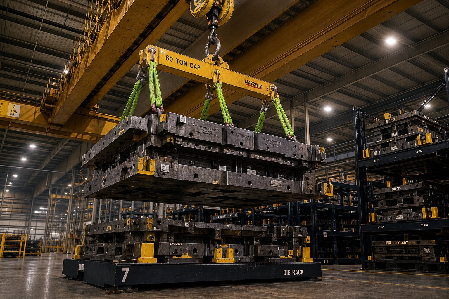
Maintenance Lifecycle and Handling for Large Die Sets
A validated die design and a successful first article mean nothing if the tool cannot be maintained, moved, and stored safely over its production life. Large die set maintenance lifecycle planning starts long before the first scheduled service interval. It starts with the facility itself. A die weighing 10, 20, or 40+ tons dictates infrastructure decisions about overhead crane capacity, floor load ratings, aisle widths, and storage configurations that smaller tooling never demands. Ignore those realities, and even a perfectly engineered die becomes a logistical bottleneck that erodes the production uptime it was built to deliver.
Handling and Logistics for Oversized Die Sets
Oversized die handling and rigging requirements shape daily operations in any large-format stamping facility. Every die change, every maintenance pull, and every storage move involves coordinating heavy lifting equipment with tight spatial constraints. Mazzella Companies notes that dies weighing 20, 40, or 60+ tons require lifting solutions far beyond standard chain slings, often driving facilities toward high-performance synthetic roundslings that weigh a fraction of steel equivalents while offering superior inspection features. The overhead crane itself must be specified to Class D service standards, built to withstand the shock loading, side loading, and swaying loads inherent to die handling.
Think about what a die change actually involves. The upper and lower halves must be separated, rigged independently, lifted clear of the press, transported across the shop floor, and set onto storage infrastructure rated for the concentrated load. Swivel hoist rings rather than eye bolts should serve as connection points, since eye bolts are prone to side pulls and metal fatigue during the angular lifts common in die handling. Falls from height add another hazard layer. Dies exceeding six feet tall require riggers to climb on top for rigging attachment, triggering OSHA fall protection requirements at four feet in general industry settings.
Floor load ratings deserve the same attention as crane capacity. A die set concentrated on four support points can easily exceed the slab's design load per square foot, particularly when storage infrastructure heavy stamping dies demand is met by stacking tools in dense rack configurations to conserve floor space. Dedicated die storage racks must be engineered, load-rated, and tagged per ASME B30.20 standards, not fabricated in-house from scrap steel and good intentions.
Resurfacing Intervals and Wear Pattern Monitoring
The die resurfacing schedule for large format tooling follows a different cadence than compact tools. Larger forming surfaces distribute wear across more area, but segmented insert interfaces, draw radii, and high-contact zones still concentrate degradation. Monitoring wear patterns on a segmented die requires systematic documentation because each insert carries its own shim stack, its own positional alignment relative to neighbors, and its own history of prior regrinding.
When a segment is pulled for resurfacing, restoring original clearances means more than just grinding the face flat. The shim thickness beneath that segment must be adjusted to compensate for material removed during grinding. Adjacent segments may need re-shimming to maintain a continuous forming surface across the joint. Without meticulous records of each segment's grind history, shim configuration, and alignment reference points, a resurfacing event can introduce as many problems as it solves.
A priority-ordered maintenance lifecycle checklist for large die sets keeps these tasks organized and ensures nothing falls through the cracks:
- Inspect all lifting hardware (hoist rings, sling connections, crane attachments) before every die move, verifying torque specifications and wear condition
- Perform visual inspection of forming surfaces, segment interfaces, and guide components after every production run
- Monitor and document wear patterns using surface profilometry or replica tape at defined stroke-count intervals
- Check and re-torque all fasteners, dowel pins, and segment retention bolts per the preventive schedule
- Lubricate all guide pins, bushings, heel blocks, and moving components according to manufacturer-specified intervals and lubricant types
- Verify cushion system performance, including nitrogen cylinder pressure checks and hydraulic system fluid condition
- Resurface worn inserts with full documentation of material removed, updated shim dimensions, and post-grind alignment verification
- Conduct full CMM or optical scan validation of the die assembly after any resurfacing or segment replacement to confirm global dimensional accuracy
Predictive maintenance methods, including vibration analysis, acoustic monitoring, and thermal imaging, supplement visual inspection by detecting subsurface cracks and abnormal wear before they reach critical failure. For large dies where unplanned downtime costs thousands per hour, predictive techniques shift maintenance from reactive to planned, keeping production schedules intact.
Partnering with Experienced Die Builders for Long-Term Support
Maintaining a large-format die set over its full production life is not purely an in-house task. Resurfacing segmented inserts, re-establishing clearances after years of cumulative grinding, replacing worn guide components, and adapting tooling for engineering changes all benefit from the original builder's knowledge of how the die was designed and assembled. The documentation trail, shim maps, segment indexing records, and clearance specifications that define a large die's baseline condition are most useful in the hands of engineers who understand the intent behind them.
For tooling engineers evaluating their die support infrastructure needs, whether planning a new large-format tool or extending the life of an existing one, partnering with a provider experienced in die structure, component integration, clearance control, and material flow management streamlines the entire lifecycle. YICHEN's custom stamping die solutions serve as a practical resource for teams navigating these challenges, connecting deep engineering expertise in punches, lifters, bypass notches, burr control, and large-format support systems to production-ready outcomes that hold up across millions of strokes.
Frequently Asked Questions About Die Stamping Support for Large Parts
1. Why can't you simply scale up a small die design for large part stamping?
Large part stamping introduces non-linear engineering challenges that prevent direct scaling. Deflection increases with the fourth power of span length, meaning a die shoe twice as wide deflects up to sixteen times more under the same load conditions. Thermal gradients span greater distances, creating differential expansion that shifts punch-to-die clearances unevenly. Force distribution grows increasingly uneven as off-center loads that compact dies absorb easily create significant angular deflection on wide-span tooling. These compounding effects require purpose-built support strategies including thicker ribbed die shoes, engineered sub-bolster grids, and multi-zone cushion control rather than proportionally enlarged versions of standard designs.
2. What is the difference between progressive and transfer dies for large parts?
Progressive dies feed a continuous metal strip through sequential stations, keeping the part attached to a carrier web. This approach hits practical limits around 600-800 mm strip width because carrier rigidity, feed precision, and material waste become unmanageable. Transfer dies solve this by separating the blank at the first station and mechanically moving discrete parts between independent operations. Transfer systems handle part envelopes exceeding 2,000 mm, improve material utilization by eliminating carrier web waste, and allow full part repositioning between stations. The trade-off is lower production speed, typically 8-25 strokes per minute versus 200-600+ for progressive tooling on small parts, and greater inter-station support infrastructure requirements.
3. How does FEA simulation reduce risk in large-format die tooling?
FEA simulation models deflection, material thinning, springback, and force distribution as interconnected phenomena before any tool steel is machined. For large dies representing investments of hundreds of thousands of dollars, simulation predicts how die shoes deflect under off-center loads, where bolster plates sag between support points, and how cushion pressure profiles affect material flow. Virtual tryout of the full forming sequence identifies splits, wrinkles, and springback accumulation station by station. Industry research shows body side panels typically require four physical rework iterations at roughly $125,000 each. FEA-driven optimization reduces or eliminates those costly iterations by validating support structure placement and compensation strategies digitally. Providers like YICHEN (yichen-group.com/stamping-die/) connect simulation-validated designs to production-ready large-format tooling.
4. What cushion system works best for large-format die stamping?
Hydraulic multi-point cushion systems are generally preferred for large-format stamping because they offer servo-controlled pressure regulation per zone, programmable force profiles, and independent zone control across extended die faces. Nitrogen cylinder arrays work for moderate footprints but suffer from progressive pressure rise during the stroke and zone-to-zone variation as array size grows. Pneumatic cushions lack the force precision and response speed needed for large draws due to air compressibility. The critical advantage of hydraulic systems is multi-zone control, allowing engineers to apply higher retention force where wrinkling risk peaks and reduced force where tearing is the concern, turning a single compromise pressure into an engineered zone-by-zone solution.
5. How do you maintain and handle die sets weighing 20 tons or more?
Large die maintenance requires facility infrastructure planning that starts with overhead crane capacity rated to Class D service standards for shock and side loading. Floor load ratings must account for concentrated point loads from die storage racks, which should be engineered and load-rated per ASME B30.20 standards. Swivel hoist rings replace eye bolts for safer angular lifts. Resurfacing segmented inserts demands documentation of each segment's shim stack, grind history, and alignment references so that clearances can be restored accurately after material removal. Predictive maintenance techniques including vibration analysis, thermal imaging, and acoustic monitoring detect subsurface issues before critical failure, shifting maintenance from reactive to planned and protecting production uptime.


